Sign In
Upload
Manuals
Brands
Siemens Manuals
Telephone Accessories
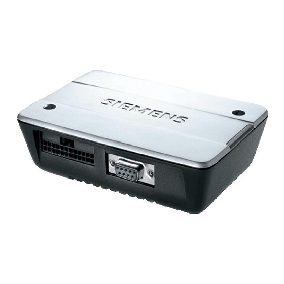
TC65 Terminal
Siemens TC65 Terminal Manuals
Manuals and User Guides for Siemens TC65 Terminal. We have
1
Siemens TC65 Terminal manual available for free PDF download: Hardware Interface Description
Siemens TC65 Terminal Hardware Interface Description (65 pages)
Cellular Engine
Brand:
Siemens
| Category:
Telephone Accessories
| Size: 1.69 MB
Table of Contents
Table of Contents
3
Document History
7
1 Introduction
8
Related Documents
8
Terms and Abbreviations
9
Regulatory and Type Approval Information
12
Directives and Standards
12
Table 1: Directives
12
Table 2: Standards of North American Type Approval
12
Table 3: Standards of European Type Approval
13
Table 4: Requirements of Quality
13
Table 5: Standards of the Ministry of Information Industry of the People's Republic of China
13
Table 6: Toxic or Hazardous Substances or Elements with Defined Concentration Limits
14
Safety Precautions
15
2 Key Features of the TC65 Terminal
17
Technical Requirements for Using TC65 Terminal
20
3 Interface Description
21
Overview
21
Figure 1: TC65 Terminal Front View
21
Figure 2: TC65 Terminal Rear View
21
Block Diagram
22
Figure 3: Block Diagram
22
Operating Modes
23
Table 7: Overview of Operating Modes
23
Terminal Circuit
24
Figure 4: TC65 Terminal Circuit Block Diagram
24
Power Supply
25
Figure 5: Female 6-Pole Western Plug for Power Supply, Ignition, Emergency off
25
Table 8: Pin Assignment of the Western Plug for Power Supply
25
Disconnecting Power Supply
26
Reset TC65 Terminal
26
Switch off TC65 Terminal
26
Switch on TC65 Terminal
26
Signal States after Startup
27
Table 9: Signal States
27
RS-232 Interface
28
Table 10: 9-Pole D-Sub (Female) RS-232
28
Figure 6: Pin Assignment RS-232 (D-Sub 9-Pole Female)
28
Audio Interface
30
Figure 7: Audio Western Plug (4-Pole Female)
30
Figure 8: Audio Block Diagram
30
Supported Audio Modes
31
Table 11: Audio Modes
31
Speech Processing
32
Antenna Interface
33
SIM Interface
33
Figure 9: Pin Location of the Molex SIM Card Holder and Position
33
Table 12: Pin Assignment - SIM Card Holder
34
IO Interface
35
Figure 10: IO Interface Connector Front View
35
Table 13: Assignment of the IO Interface Connector
36
Figure 11: Location of GPIO Pins
37
Gpios
37
I²C Interface
38
Table 14: I²C Interface - Signal Description
38
Using GPIO Pin10 as Pulse Counter
38
SPI Interface
39
Table 15: SPI Interface - Signal Description
39
Figure 12: Characteristics of SPI Modes
40
Analog-To Digital Converter (ADC)
41
Figure 13: ADC Balanced Amplifier
41
Table 16: ADC Signal Description
41
ON/OFF Switch
42
Power Supply
42
RTC Backup Supply
42
Table 17: RTC Signal Description
42
VDD Supply
42
Status LED
43
4 Mechanical Characteristics
44
Table 18: Mechanical Characteristics
44
Figure 14: Mechanical Dimensions
45
Figure 15: Tyco Micro Mate-N-LOK Series on the TC65 Terminal
46
Figure 16: Mating Connector Tyco Micro Mate-N-LOK Series
46
Figure 17: Receptacle Contact for Tyco Micro Mate-N-LOK Series
46
Figure 18: Mechanical Dimensions of the Tyco Mate_N_Lok Connector on the TC65
47
Recommended Mating Connector
47
Table 20: Ordering Information for Mating Connector Tyco Micro Mate-N-LOK
47
IO Interface Connector
46
Table 19: Electrical and Mechanical Characteristics of the Micro Mate-N-LOK Connector
46
5 Electrical and Environmental Characteristics
48
Table 21: Absolute Maximum Ratings
48
Table 22: Operating Conditions
49
Table 23: Highest Temperatures
49
Table 24: Longest Duration until 81°C Are Reached
50
Table 25: Longest Duration When GPRS Class Change Does Not Work Properly
50
Characteristics of the Power Supply
51
Table 26: Characteristics of the Power Supply
51
Characteristics of On/Off Control
52
Table 27: Characteristics On/Off Control
52
Characteristics of the RS-232 Interface
53
Characteristics of the SIM Interface for Use with 3V Cards
53
Table 28: Characteristics of the RS-232 Interface
53
Table 29: Characteristics of the SIM Interface for Use with 3V Cards
53
Characteristics of the SIM Interface for Use with 1.8V Cards
54
Table 30: Characteristics of the SIM Interface for Use with 1.8V Cards
54
Characteristics of the Audio Interface
55
Table 31: Characteristics of the Audio Interface
55
Audio Parameters Adjustable by at Commands
56
Table 32: Audio Parameters Adjustable by at Commands
56
Characteristics of the Gpios
57
Characteristics of the Pulse Counter
57
Table 33: Characteristics of the Gpios
57
Table 34: Characteristics of the Pulse Counter
57
Characteristics of the I 2 C Interface
58
Characteristics of the SPI Interface
58
Table 35: Characteristics of the I2C Interface
58
Table 36: Characteristics of the SPI Interface
58
Characteristics of the ADC Interface
59
Characteristics of the RTC Supply
59
Table 37: Characteristics of the ADC Interface
59
Table 38: Characteristics of the RTC Supply
59
RF Connector
60
Table 39: RF Connector
60
6 Full Type Approval
61
Siemens Reference Setup
61
Figure 19: Reference Equipment for Approval
61
Compliance with FCC Rules and Regulations
62
Cable Requirements
62
Restrictions
63
CE Conformity
63
Electromagnetic Compatibility (EMC)
63
7 List of Parts and Recommended Accessories
64
Table 40: List of Parts and Accessories
64
Advertisement
Share and save
Advertisement
Related Products
Siemens TC65
Siemens TC63
Siemens TC60 series
Siemens TC66 series
Siemens TC6 SERIES
Siemens TC6....GB
Siemens TC12
Siemens TC865 series
Siemens TC3 Series
Siemens TC3A0307
Siemens Categories
Controller
Control Unit
Industrial Equipment
Washer
Switch
More Siemens Manuals
Login
Sign In
OR
Sign in with Facebook
Sign in with Google
Upload manual
Upload from disk
Upload from URL