Sign In
Upload
Manuals
Brands
Siemens Manuals
Switch
SIVACON S 8PQ Series
Siemens SIVACON S 8PQ Series Manuals
Manuals and User Guides for Siemens SIVACON S 8PQ Series. We have
3
Siemens SIVACON S 8PQ Series manuals available for free PDF download: Operating Instructions Manual
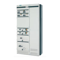
Siemens SIVACON S 8PQ Series Operating Instructions Manual (40 pages)
Design-verified low-voltage switchboard
Brand:
Siemens
| Category:
Switch
| Size: 5.52 MB
Table of Contents
SIVACON Bauartgeprüfte Niederspannungsschaltanlage S8 - Felder mit Abzweigen in Einschubtechnik Design-Verified Low-Voltage Switchboard S8- Cubicles with Feeders in Withdrawable Design Betriebsanleitung / Operating Instructions Bestell-Nr. / Order No.: 8PQ9800-3AA48
3
Table of Contents
3
Beschreibung des MCC-Feldes
5
Feldaufbau
5
Beschreibung des Feldaufbaues
5
Varianten der Feldbestückung
5
Description of the MCC Cubicle
5
Cubicle Arrangement
5
Description of the Cubicle Arrangement
5
Variations of the Cubicle Placement
5
Einbauortkennzeichnung
6
Installation Location Indication
6
Maximale Feldgewichte
8
Vertikale Feldschiene
8
Aufbau
8
Shutter und Abdeckungen für Feldschiene
8
Maximum Cubicle Weights
8
Vertical Distribution Busbar
8
Design
8
Shutter and Covers for Distribution Bars
8
Bemessungsströme der Feldschiene
9
Rated Currents for the Distribution Bars
9
Funktionsweise und Aufbau der Einschübe
10
Einschubgrößen
10
Functionality and Design of Withdrawable Units
10
Sizes of Withdrawable Units
10
Mögliche Stellungen der Einschübe
11
Possible Positions of Withdrawable Units
11
Normaleinschübe
14
Fachaufbau für Normaleinschübe
14
Aufbau Normaleinschub
14
Standard Withdrawable Units
14
Compartment Design for Standard Withdrawable Units
14
Design of Standard Withdrawable Units
14
Technische Daten
15
Technical Data
15
Montage
16
Elektrische Anschlüsse
18
Kabelraum Frontanschluss
18
Kabelanschluss Hauptstromkreis
18
Anschlussquerschnitte
21
Steuerstromkreise
21
Steuerklemmblock mit Push-In Anschluss
21
Steuerklemmblock mit Schraubanschluss
22
Betrieb
23
Inbetriebnahme
23
Schaltstellung bei der Anlieferung
23
Betätigungswerkzeuge bei Anlieferung
23
Einstellen der Überstromschutzeinrichtungen
24
Bedienung der Einschübe
25
Einschübe aus der Trennstellung in die Betriebsstellung Bringen
25
Einschübe aus der Betriebsstellung in die Trennstellung Bringen
26
Einschübe aus der Trennstellung in die Teststellung Bringen
26
Einschübe aus der Teststellung in die Trennstellung Bringen
26
Handhabung Normaleinschub
27
Mechanische Codierung
28
Abschließbarkeit von Einschüben
29
Abschließbarkeit von Normaleinschubfächern
30
Einschalten
30
Lagerung der Einschübe
30
Instandhaltung
31
Inspektion
31
Wartung
31
Reinigen
31
Fetten
32
Instandsetzung
33
Maßnahmen nach Kurzschluss- und Überlastauslösung
33
Wechseln von NH- Sicherungseinsätzen
33
Austausch von Geräten
34
Umbau
35
Austauschen von Einschüben
35
Einschubfächer Umrüsten
35
2.1 2.2 2.2.1 2.2.1.1 2.2.1.2 2.2.2 2.2.2.1 2.2.2.2
16
Mounting
16
Access to Main Busbar Joint for Main Busbar at Rear
17
Electrical Connections
18
Cable Compartment, Front Access
18
Cable Connection, Main Circuit
18
Cable Cross-Sections
21
Control Circuits
21
Control Terminal Block with Push-In Terminal
21
Control Terminal Block with Screw Terminal
22
Operation
23
Commissioning
23
Switching Positions as Supplied
23
Actuating Tools as Supplied
23
Configuring the over Current Protection Devices
24
Operating the Withdrawable Units
25
Setting Withdr. Units from the Disconnected to Connected Position
25
Setting Withdr. Units from the Connected to Disconnected Position
26
Setting Withdrawable Units from the Disconnected to Test Position
26
Setting Withdrawable Units from the Test to Disconnected Position
27
Handling Standard Withdrawable Units
27
Mechanical Coding
28
Locking Capability of Withdrawable Units
29
Locking Capability of Compartment for Standard Withdrawable Unit
30
Switching on
30
Storing of Withdrawable Units
30
Care
31
Inspection
31
Preventive Maintenance
31
Cleaning
31
Greasing
32
Repair
33
Measures after Short Circuit or Overload Release
33
Changing of LV HRC Fuse Links
33
Renewing of Devices
34
Retrofit
35
Renewing Withdrawable Units
35
Re-Equipping Withdrawable Unit Compartments
35
Upgrade Compartment with Shutter
36
Removing of Shutter
37
Compartment Modification, Connection from Front
38
Compartment for Rear Connection
39
Entsorgung
40
Fitting and Removing Compartment Bottom
40
Disposal
40
Advertisement
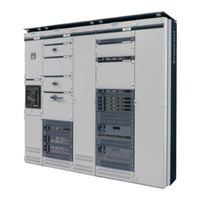
Siemens SIVACON S 8PQ Series Operating Instructions Manual (61 pages)
Brand:
Siemens
| Category:
Power distribution unit
| Size: 10.65 MB
Table of Contents
Table of Contents
3
MCC 机柜说明
5
机柜结构
5
机柜结构说明
5
机柜装备类型
5
Description of the MCC Cubicle
5
Cubicle Arrangement
5
Description of Cubicle Arrangement
5
Variations of Cubicle Placement
5
Installation Location Indication
6
Maximum Cubicle Weights
8
Vertical Distribution Busbar
8
Design
8
Shutter and Covers for Distribution Bars
8
Rated Currents for the Distribution Bars
9
Functionality and Design of Withdrawable Units
10
Sizes of Withdrawable Units
10
Possible Positions of Withdrawable Units
11
Standard Withdrawable Units
14
Compartment Design for Standard Withdrawable Units
14
Design of Standard Withdrawable Units
14
Miniature Withdrawable Units
15
Compartment Design for Miniature Withdrawable Units
15
Design of Miniature Withdrawable Units
15
Technical Data
16
Mounting
17
主母线位置后端主母线系统入口
18
电气连接
19
电缆间前置连接
19
小型抽屉模块的主电路电缆连接
19
标准抽屉模块的主电路电缆连接
19
连接横截面
22
控制电路
22
采用嵌入式连接的控制接线盒
22
采用螺旋连接的控制接线盒
23
交货时的开关位置
24
交货时的操作工具
24
过电流保护装置的设置
25
抽屉模块的操作
27
将抽屉模块从分断位置切换至工作位置
27
将抽屉模块从工作位置切换至分断位置
28
将抽屉模块从分断位置切换至测试位置
28
将抽屉模块从测试位置切换至分断位置
28
标准抽屉模块的操作
29
小型抽屉模块的操作
30
机械编码装置
30
抽屉模块可上锁
31
标准抽屉模块抽格可上锁
32
抽屉模块的存放
32
低压高分断能力熔断体的更换
35
更换设备
36
更换抽屉模块
37
改装抽格
37
标准抽屉模块抽格中的百叶板
38
小型抽屉模块抽格中的百叶板
39
拆除百叶板
39
标准抽屉模块的抽格改装,从前面接入设备
40
标准抽屉模块的抽格,从后面接入设备
41
拆卸和安装抽屉架
42
小型抽屉模块的抽格,从前面接入设备
43
拆卸小型抽屉模块的抽格
43
安装小型抽屉模块的抽格
48
小型抽屉模块的抽格,从后面接入设备
52
拆卸小型抽屉模块的抽格
52
安装小型抽屉模块的抽格
57
Mounting Miniature Withdrawable Unit Compartments
57
将小型抽屉模块改装为其它抽屉模块规格
61
Siemens SIVACON S 8PQ Series Operating Instructions Manual (11 pages)
Brand:
Siemens
| Category:
Industrial Equipment
| Size: 0.91 MB
Table of Contents
Table of Contents
3
Descripción de la Celda con Convertidores de Frecuencia
4
Estructura de la Celda
4
Estructura del Compartimento y Variantes para Unidades
5
Extraíbles con Convertidores de Frecuencia
5
Estructura de las Unidades Extraíbles con Convertidor
6
Conexiones Eléctricas
7
En Servicio
9
Condiciones del Entorno
9
Puesta en Marcha
9
Control de Ventiladores en la Unidad Extraíble
9
Cuidado
10
Inspección
10
Mantenimiento
10
Reparación
10
Sustitución de Ventiladores
10
Medidas Luego de un Corto Circuito O una sobre Carga
11
Eliminación de Residues
11
Descargo de Responsabilidad
11
Advertisement
Advertisement
Related Products
Siemens SIMATIC NET RUGGEDCOM RSG2100
Siemens SIMATIC NET SCALANCE XM-400
Siemens SCALANCE XR-300M PoE
Siemens SIMATIC NET RUGGEDCOM M2100
Siemens SIMATIC NET RUGGEDCOM RS900G
Siemens SIMATIC NET SCALANCE XP-200
Siemens SIMATIC NET SCALANCE XC-100
Siemens SIMATIC NET SCALANCE XM-400 Series
Siemens SIMATIC NET SCALANCE XC-200
Siemens SIMATIC NET RUGGEDCOM RS900L
Siemens Categories
Industrial Equipment
Controller
Control Unit
Oven
Washer
More Siemens Manuals
Login
Sign In
OR
Sign in with Facebook
Sign in with Google
Upload manual
Upload from disk
Upload from URL