Sign In
Upload
Manuals
Brands
Siemens Manuals
Industrial Equipment
SIPART PS2 BT
Siemens SIPART PS2 BT Manuals
Manuals and User Guides for Siemens SIPART PS2 BT. We have
1
Siemens SIPART PS2 BT manual available for free PDF download: Operating Instructions Manual
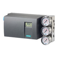
Siemens SIPART PS2 BT Operating Instructions Manual (320 pages)
Electropneumatic positioners
Brand:
Siemens
| Category:
Industrial Equipment
| Size: 16 MB
Table of Contents
Qualified Personnel
2
Disclaimer of Liability
2
Table of Contents
3
Introduction
11
Purpose of this Documentation
11
User Documentation
11
Scope of Documentation
11
Document History PS2 with and Without HART
13
Product Compatibility
16
Designated Use
16
Checking the Consignment
16
Cybersecurity Information
17
Transportation and Storage
18
Notes on Warranty
18
Safety Information
19
Precondition for Use
19
Warning Symbols on the Device
19
Laws and Directives
19
Conformity with European Directives
20
Conformity with UK Regulations
20
Product Approval and UL Compliance
20
Improper Device Modifications
21
Improper Modification on Positioner 6DR5
21
Requirements for Special Applications
21
Use in Hazardous Areas
22
Description
23
Structure
23
Overview of Structure
23
Manufacturer Nameplate
26
Explanation of Ex Information
26
Device Components
27
Overview of Device Components (Without Ex)
27
Overview of Device Components (Ex D)
28
Mode of Operation
28
Pneumatic Actuator
28
Mode of Operation of the HART Function
29
HART System Configuration
29
Simatic Pdm
30
Installing/Mounting
31
Basic Safety Instructions
31
Proper Mounting
33
Mounting to Linear Actuator
34
Mounting to Part-Turn Actuator
41
Installing Option Modules
46
Basic Safety Instructions
46
Opening the Positioner
47
Digital I/O Module (DIO) 6DR4004-6A / -8A
50
Device Features
51
Analog Output Module (AOM) 6DR4004-6J / -8J
52
Inductive Limit Switches (ILS) and Mechanic Limit Switches (MLS)
53
Inductive Limit Switches (ILS) - Mode of Operation and Equipment Features
53
Mechanic Limit Switches (MLS) - Mode of Operation and Equipment Features
54
Installing Inductive Limit Switches (ILS) and Mechanic Limit Switches (MLS)
55
Setting Limits for Inductive Limit Switches (ILS)
63
Setting Limits for Mechanic Limit Switches (MLS)
65
Analog Input Module (AIM) 6DR4004-6F / -8F
66
Closing the Positioner
70
Setting and Locking the Transmission Ratio
74
Connection
77
Basic Safety Instructions
77
Two-Wire Mode
80
Electromagnetic Compatibility
80
Electrical Wiring
81
Electronics
81
HART: Split Range
83
Option Modules
84
Digital I/O Module (DIO) 6DR4004-6A / -8A
84
Analog Output Module (AOM) 6DR4004-6J / -8J
84
Inductive Limit Switches (ILS) 6DR4004-6G / -8G
85
Mechanic Limit Switches (MLS) 6DR4004-6K
85
Analog Input Module (AIM) 6DR4004-6F / -8F
86
Optional Version M12 Device Plug
87
M12 Connector in Basic Device with and Without HART
87
M12 Connector in Basic Device with Analog Output Module (AOM) 6DR4004-6J / -8J (-Z D53)
87
In the Basic Unit with Position Transmitter (-Z D54)
88
In the Basic Unit with Digital I/O Module (DIO) 6DR4004-6A / -8A (-Z D55)
88
In the Basic Unit with Inductive Limit Switches (ILS) 6DR4004-6G /-8G (-Z D56)
88
In the Basic Unit with Mechanic Limit Switches (MLS) 6DR4004-6K (-Z D57)
89
Pneumatic Connection
89
Basic Safety Instructions for the Pneumatic Connection
89
Pneumatic Connection in Non-Flameproof Enclosure
90
Structure of Pneumatic Connection
90
Integrated Pneumatic Connection
90
Pneumatic Connection in the Flameproof Enclosure
92
Behavior in Case of Failure of the Electrical Auxiliary Power And/Or the Supply Pressure PZ
92
Restrictors
94
Operating
95
Operating Elements
95
Display
95
Buttons
96
Firmware Version
97
Operating Modes
98
Overview of Operating Modes
98
Changing the Operating Mode
99
Overview of Configuration
100
Description of Operating Modes
100
Manual Mode (MAN)
101
Optimization of Controller Data
102
Commissioning
107
Basic Safety Instructions
107
Overview
109
General Information about Commissioning
109
Sequence of Automatic Initialization
110
Determining the Actuator Type
111
Starting Automatic Initialization
112
RUN 1: Determination of Direction of Action
112
RUN 2: Determination of Travel
112
RUN 3: Determination and Display of Travel Time (Leakage Test)
113
RUN 4: Minimization of Positioning Increments
113
RUN 5: Optimization of Transient Response
114
RUN 6: Inclusion of Valve Signature
114
End
114
Manual Adjustment of the Pressure Sensors
114
Purge Air Switching
115
Setting the Friction Clutch
115
Commissioning Linear Actuators
117
With Internal Wear-Free, Non-Contacting Position Detection
117
Preparing Linear Actuators for Commissioning
117
Automatic Initialization of Linear Actuators
117
Manual Initialization of Linear Actuators
119
With Potentiometer, Friction Clutch and Gearbox
121
Preparing Linear Actuators for Commissioning
121
Automatic Initialization of Linear Actuators
122
Manual Initialization of Linear Actuators
124
Commissioning Part-Turn Actuators
127
With Internal Wear-Free, Non-Contacting Position Detection
127
Preparing Part-Turn Actuators for Commissioning
127
Automatic Initialization of Part-Turn Actuators
127
Manual Initialization of Part-Turn Actuators
129
With Potentiometer, Friction Clutch and Gearbox
131
Preparing Part-Turn Actuators for Commissioning
131
Automatic Initialization of Part-Turn Actuators
132
Manual Initialization of Part-Turn Actuators
133
Canceling Initialization
136
Replacing the Positioner During Operation
136
Introduction
136
General Requirements
137
Replacing the Positioner with Communication
138
Replacing the Positioner Without Communication
143
Parameter Assignment
145
Overview of Parameters
145
Configuration Schematic for Parameter Operating Principle
148
Overview of Parameters 1 to 52 (HART)
149
Description of Parameters
152
Initialization Parameters 1 to 5
152
1.YFCT' Type of Actuator
152
Additional Information
153
YAGL' Rated Angle of Rotation of Feedback
154
YWAY' Range of Stroke
154
INITA' Initialization (Automatic)
155
INITM' Initialization (Manual)
156
Application Parameters 6 to 52
156
SCUR' Current Range of Setpoint
156
SDIR' Setpoint Direction
157
SPRA' Setpoint Split Range Start / '9.SPRE' Setpoint Split Range Start End
157
'10.TSUP' Setpoint Ramp up / '11.TSDO' Setpoint Ramp down
158
'12.SFCT' Setpoint Function
159
Sl0
159
'34.DEBA' Deadband of Closed-Loop Controller
160
YA' Start of Manipulated Variable Limit / '36.YE' End of Manipulated Variable Limit
161
'37.YNRM' Standardization of Manipulated Variable
161
'38.YDIR' Direction of Manipulated Variable for Display and Position Feedback
163
'39.YCLS' Tight Closing/Fast Closing with Manipulated Variable
163
'40.YCDO' Value for Tight Closing/Fast Closing down
164
'41.YCUP' Value for Tight Closing/Fast Closing up
164
'42.DI1' / '43.DI2' Function Digital Input
165
'44.AFCT' Alarm Function
166
'45.A1' / '46.A2' Response Threshold of Alarm
168
'47.\\FCT' Function of the Fault Message Output
168
'48.\\TIM' Monitoring Period for Setting of Fault Message 'Control Deviation
169
'49.\\LIM' Response Threshold of Fault Message 'Control Deviation
169
PRST' Preset (HART/FF)
170
'51.PNEUM' Pneumatics Type
170
'52.XDIAG' Activating for Extended Diagnostics
171
Setting Description
172
Diagnostic Values
174
Displaying Diagnostic Values
174
Diagnostic Values Overview
175
Diagnostic Values for Commissioning and Initialization
177
Diagnostic Value "Manipulated Variable Lower Endstop (0% Position)" (21.P0)
177
Diagnostic Value "Manipulated Variable Upper Endstop (100% Position)" (22.P100)
179
Diagnostic Values "Pulse Length UP" (23.IMPUP) / "Pulse Length DOWN" (24.IMPDN)
181
Diagnostic Value "Pulse Interval" (25.PAUTP)
182
Diagnostic Values "Slow Step Zone UP" (28.SSUP) / "Slow Step Zone up DOWN" (29.SSDN)
182
Diagnostic Values "Prediction UP" (47.PRUP) / "Prediction DOWN" (48.PRDN)
183
Diagnostic Value "Procedure for Adjustment of Electronics" (73.RPL_E)
185
Diagnostic Value "Position Adjustment" (74.TRIM)
186
Overview of the Assignment of the HART Variables
187
Functional Safety
189
Range of Applications for Functional Safety
189
Safety Function
189
Type a - Safety Integrity Level (SIL)
192
Settings
193
Safety Characteristics
194
Maintenance/Check
195
Service and Maintenance
197
Basic Safety Instructions
197
Maintenance
197
Cleaning
198
Cleaning the Enclosure
198
Positioners 6DR5..0, 6DR5..3 and 6DR5..5
198
Positioners 6DR5..1, 6DR5..2 and 6DR5..6
199
Maintenance and Repair Work
199
Replacing Electronics
201
Installation
201
Replacing the Pneumatic Block
202
Replace the Pressure Sensor Module
204
Overview Screen
204
Return Procedure
206
Disposal
207
Diagnostics and Troubleshooting
209
Display Messages with Error Code
209
Display Messages
220
Troubleshooting
225
Technical Specifications
227
HART Operating Conditions
227
Pneumatic Data for All Device Versions
228
Construction for All Device Versions
229
Controller for All Device Versions
231
Explosion Protection SIPART PS2
231
Electrical Data (HART)
231
Electrical Data for Pressure Sensor Module
233
Communication (HART)
233
Technical Data for Natural Gas as Actuator Medium
234
Option Modules
235
Digital I/O Module (DIO) 6DR4004-6A / -8A
235
Analog Output Module (AOM) 6DR4004-6J / -8J
236
Inductive Limit Switches (ILS) 6DR4004-6G / -8G
237
Mechanic Limit Switches (MLS) 6DR4004-6K
238
Analog Input Module (AIM) 6DR4004-6F / -8F
239
Internal NCS Module 6DR4004-5L / 6DR4004-5LE
240
Other Technical Specifications
240
Dimension Drawings
241
Positioner in Non-Flameproof Enclosure
241
Terminal Strip for Positioners
242
Positioner in Flameproof Enclosure
243
Product Documentation and Support
245
Technical Support
245
Product Documentation
246
Bluetooth
247
Connecting SIPART PS2 BT
247
Procedure
248
Connecting Field Device with SITRANS Mobile IQ App
252
Default Password
253
Reset Password
253
Security Information
253
Access Management
253
Information for Radio Approvals
255
Fcc Regulatory Information
256
Technical Specifications SITRANS AW050
257
Dimension Drawing of SITRANS AW050 Bluetooth Adapter
257
External Position Detection
259
Introduction
259
Non-Contacting Sensor
259
Mode of Operation
259
Mounting the NCS
260
Mounting the NCS to the Part-Turn Actuator
261
Incorrect Mounting
262
Mounting the NCS to a Linear Actuator up to 14 MM (0.55 Inch)
263
Mounting the NCS to a Linear Actuator > 14 MM (0.55 Inch)
265
Connecting NCS to Analog Input Module (AIM)
268
Wiring Diagram
268
Commissioning of NCS
269
Prerequisites / Default Settings
269
Initialization of Part-Turn Actuators
270
Initializing Linear Actuators with a Stroke Range up to 14 MM (0.55 Inch)
270
Initializing Linear Actuators with a Stroke Range > 14 MM (0.55 Inch)
270
External NCS Sensors 6DR4004-6N/8N and 6DR4004-2ES
271
Dimensional Drawing of Non-Contacting Sensor
272
NCS Sensor Scope of Delivery
273
Scope of Delivery of NCS for Part-Turn Actuators
273
Scope of Delivery of NCS for Linear Actuators up to 14 MM (0.55 Inch)
273
Scope of Delivery of NCS for Linear Actuators > 14 MM (0.55 Inch)
274
External Position Detection
275
Mode of Operation for External Position Detection
275
Installation of External Position Detection System
276
Connecting to Analog Input Module (AIM)
276
Technical Specifications of the External Position Detection System
277
Rated Conditions for External Position Detection
277
Electrical Data for External Position Detection
277
Internal NCS Module (Incs)
281
Internal NCS Module (Incs) 6DR4004-5L / -5LE
281
Pressure Gauge Blocks
285
Pressure Gauge Block
285
Venting Gauge Block
286
Dimension Drawing of Pressure Gauge Blocks
287
Sealing Plug / Thread Adapter
289
Purpose
289
Safety Instructions
289
Technical Specifications
290
Dimension Drawings
291
Booster
293
Booster Introduction
293
Mounting a Booster
293
Tightening Screws
297
Booster Commissioning
298
RUN 3: Determination and Display of Travel Time (Leakage Test)
299
Booster Dimension Drawings
300
For Positioners in Non-Flameproof Enclosure
300
For Positioners in Flameproof Enclosure
301
Technical Specifications of Booster
302
Positioner with Remote Electronics
303
Introduction to Remote Electronics
303
19-Inch Control Unit
303
Description of 19-Inch Control Unit 4 to 20 Ma
303
Connecting the 19-Inch Control Unit 4 to 20 Ma
304
Grounding Concept for 19-Inch Control Unit 4 to 20 Ma
304
Electrical Connection of 19" Slide-In Module 4 to 20 Ma
307
Technical Specifications for 19-Inch Control Unit 4 to 20 Ma
310
Cable Specification
311
Dimension Drawing for 19-Inch Control Unit 4 to 20 Ma
311
Positioner Without Electronics 6DR5910
312
Abbreviations
313
Abbreviations for PS2 Positioners
313
Abbreviations
314
Index
317
Advertisement
Advertisement
Related Products
Siemens PolyBlend PB200-2
Siemens PowerLink CM
Siemens POM4220 Highend
Siemens POM4220 Flexible
Siemens Climatix ECO POL224.00
Siemens Climatix ECO POL224.05
Siemens POWERMOBIL SP
Siemens Compact PLUS 6SE7024-1EP85-0AA0
Siemens Compact PLUS 6SE7024-1EP85-0AA1
Siemens PolyBlend PB600-4.5
Siemens Categories
Industrial Equipment
Control Unit
Controller
Oven
Washer
More Siemens Manuals
Login
Sign In
OR
Sign in with Facebook
Sign in with Google
Upload manual
Upload from disk
Upload from URL