Sign In
Upload
Manuals
Brands
Siemens Manuals
Control Unit
Maxum II PD PA AP
Siemens Maxum II PD PA AP Manuals
Manuals and User Guides for Siemens Maxum II PD PA AP. We have
1
Siemens Maxum II PD PA AP manual available for free PDF download: Service Manual
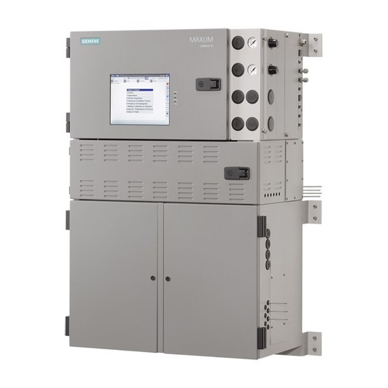
Siemens Maxum II PD PA AP Service Manual (110 pages)
Valves and Oven Components
Brand:
Siemens
| Category:
Control Unit
| Size: 18 MB
Table of Contents
Table of Contents
3
1 Oven Types
7
Isothermal Air Bath Oven Heater System (Single and Split)
8
Heater Assembly Purge
8
Figure 1-1 Pressure Switch and Purge Control Module
8
Figure 1-2 Timing Coil for Pressure Switch
9
Temperature Limiting
10
Figure 1-3 Airbath Oven Heater Control Loop
10
Programmed Temperature Air Bath Oven Heater System
11
Figure 1-4 Programmed Temperature Airbath Oven (with Deflector)
11
IS Probe and Barrier
12
Figure 1-5 Programmed Temperature Airbath Oven Component Locations
12
Isothermal Airless Oven Heater System
13
Figure 1-6 Airless Oven
13
Figure 1-7 Location of Temperature Probes and Heaters in Airless Oven
14
Figure 1-8 Airless Oven Heater Control Loop
14
Maintenance Considerations for Airbath and Airless Ovens
15
Airbath Heater Assembly Replacement
16
Airless Heater Replacement
16
Figure 1-9 Airless Oven Heater Locations
17
Modular Oven Heater System
18
Figure 1-10 Typical Modular Oven Configuration
18
Maintenance Considerations for Modular Ovens
19
Figure 1-11 Heater and RTD Tubes for the Modular Oven
19
2 Using Small Tubing Fittings
21
Figure 2-1 Valco Fitting
21
Figure 2-2 Siemens and Valco Fittings Compared
22
Figure 2-3 Siemens Fittings Assembly
22
3 Temperature Control Module (TCM)
23
Figure 3-1 Temperature Control Module Connections
23
Replacing a TCM
24
4 Valves
27
Solenoid Valves
27
Solenoid Valve Control Module (SVCM)
27
Figure 4-1 Solenoid Valve Control Module (SVCM)
27
Figure 4-2 Solenoid Control Module
28
Table 4-1 Digital Output Solenoid Valve Groups
29
Table 4-2 SVCM I/O Assignments
29
Table 4-3 SVCM Fault Indicators
29
Replacing a Solenoid Valve
30
Table 4-4 SVCM Specifications
30
Liquid Injection Valve
31
Figure 4-3 SLIV Installation Details
33
Figure 4-4 SLIV Heater and Probe Connections in the Electronics Cabinet
34
Figure 4-5 Vaporization Temperature
36
SLIV Maintenance Overview
37
Liquid Injection Valve Component Locations
38
Troubleshooting
39
Service Procedures
40
Siemens Liquid Injection Valve Specifications
44
Table 4-5 Configuration
44
Model 50 Valve
45
Table 4-6 Siemens Liquid Injection Valve
45
Table 4-7 Liquid Sample Inlet Conditions
45
Basic Maintenance: Model 50 Valve
46
Preventing Port to Port Leaks
46
Maintenance Considerations
46
Model 50 Valve Maintenance Procedure
48
Model 50 Valve Specifications
53
Table 4-8 Configuration
53
Table 4-9 Performance and Requirements
53
Model 20 Valve
54
Basic Maintenance
54
Maintenance Considerations
54
Table 4-10 Dimensions
54
Diagnostic Procedures
56
Model 20 Valve Cap Maintenance Procedure
57
Disassembly and Cleaning
59
M20 Description
59
M20 Intended Users
60
M20 Safety and Certification Information
60
M20 Procedure - Overview
60
M20 Procedure - Maintenance Facility
60
M20 Procedure - Figures
61
M20 Procedure - Cleaning of Parts
62
M20 Procedure - Valve Cap Disassembly
63
M20 Procedure - Actuator Disassembly
63
M20 Procedure - Actuator Reassembly
65
M20 Procedure - Valve Cap Reassembly
66
Model 20 Valve Specifications
67
Model 20 HT Valve
68
M20HT Description
68
M20HT Intended Users
68
M20HT Safety and Certification Information
69
M20HT Procedure - Overview
69
M20HT Procedure - Maintenance Facility
69
M20HT Procedure - Figures
70
Figure 4-18 Cross Section View of Model 20 HTV
71
Figure 4-19 Exploded View of Model 20 HTV
72
M20HT Procedure - Cleaning of Parts
73
M20HT Procedure - Valve Cap Disassembly
73
M20HT Procedure - Actuator Disassembly
74
M20HT Procedure - Actuator Re-Assembly
75
Figure 4-20 Assembling Bal-Seal (13) on Piston (15)
76
Figure 4-21 Installing Bal-Seal (20) in Piston Groove (18)
77
M20HT Procedure - Valve Cap Re-Assembly
79
Model 20 High Temperature Valve Specifications
80
Model 11 Valve
81
Valve Operation
82
Figure 4-26 Model 11 Operational Diagrams
84
Model 11 Maintenance Overview
85
M11 Intended Users
85
M11 Safety and Certification Information
85
Diagnostic Procedures
86
M11 Procedure - Maintenance Facility
87
M11 Procedure - Figures
88
Figure 4-28 Model 11 Valve Cap Exploded View
89
Figure 4-30 Valve Body Exploded View
90
Mini-Maintenance Procedures (Valve Cap and Fittings)
91
M11 Procedure - Valve Cap Disassembly
91
Figure 4-34 M11 - 4 Exploded View of Model 11 Valve Body
92
M11 Procedure - Cleaning of Parts
93
M11 Procedure - Valve Cap Cleaning and Re-Assembly
94
Maxi-Maintenance Procedures (Valve Body)
96
M11 Procedure - Valve Body Disassembly
96
M11 Procedure - Valve Body Cleaning
97
M11 Procedure - Valve Body Re-Assembly
97
Model 11 Valve Specifications
98
Model 11 Low Dead Volume Valve (LDV) Specifications
99
Live T Switch
100
Valco Rotary Valves
101
Valco A4 C6UWE Valve Specifications
101
5 Heaters
103
Air Bath Oven Heaters
103
Figure 5-1 1400 Watt Air Bath Heater
104
Airless Oven Heaters
106
Figure 5-4 Airless Oven Heater Locations in Mezzanine Area
107
Appendix A - Contact Information
109
Product Information Availability
109
Contacts
110
A.2 Contacts
110
Advertisement
Advertisement
Related Products
Siemens SITRANS FM MAG 8000 IIoT
Siemens MSS Basic
Siemens MXG461B Series
Siemens MXG461B15-1.5
Siemens MXG461B20-5
Siemens MJ-5
Siemens MM7033
Siemens MCN11
Siemens SIMATIC NET MM992-4CUC
Siemens SIMATIC NET MM992-4SFP
Siemens Categories
Industrial Equipment
Control Unit
Controller
Oven
Washer
More Siemens Manuals
Login
Sign In
OR
Sign in with Facebook
Sign in with Google
Upload manual
Upload from disk
Upload from URL