Sign In
Upload
Manuals
Brands
SICK Manuals
Smoke Alarm
VISIC50SF
SICK VISIC50SF Manuals
Manuals and User Guides for SICK VISIC50SF. We have
1
SICK VISIC50SF manual available for free PDF download: Operating Instructions Manual
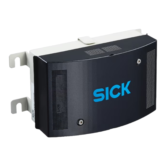
SICK VISIC50SF Operating Instructions Manual (108 pages)
Smoke Detector in Tunnels
Brand:
SICK
| Category:
Smoke Alarm
| Size: 6 MB
Table of Contents
Table of Contents
4
Important Information
9
About this Document
9
Responsibility of User
9
Intended Use
10
Purpose of the Device
10
Product Identification
10
Mounting Location
10
Product Description
11
Features of the VISIC50SF
11
Device Versions
12
Standard Components: VISIC50SF Visibility Measurement (K-Value)
12
Optional Equipment
12
Measuring Principle
16
Interior View of the VISIC50SF
16
Interfaces
19
Analog Interfaces Characteristics
19
Digital Interfaces Properties
19
Modbus-RTU Interface Characteristics
19
Mounting and Electrical Installation
20
Safety Information
20
Material Required
21
Preparing the Mounting Location
22
Mounting
22
Scope of Delivery
22
Mounting the VISIC50SF
22
Mounting the Connection Unit (Optional)
26
Mounting the TAD Control Unit (Optional)
27
Mounting of Temperature Sensor PT1000 (Optional)
27
Wiring of VISIC50SF
29
Safety Information
29
Connecting the LED
29
Wiring of Analog Outputs, Relay Outputs and Voltage Supply
31
Bus Interface Wiring
32
Shielding
32
Connection Unit Wiring
34
TAD Control Unit Wiring
35
Connections
36
Standard Version
36
VISIC50SF with Connection Unit
36
VISIC50SF with TAD Control Unit
37
Commissioning
38
Commissioning, Step by Step
38
Bus Connections
40
Modbus-RTU (Integrated in the VISIC50SF Standard Version)
40
Modbus-RTU Data Format
40
Modbus-RTU Baud Rates
40
Read Holding Register
41
Modbus-RTU Read Coil (0X01)
42
PROFIBUS DP-V0 (Optional)
42
PROFIBUS Addressing
42
PROFIBUS DP-V0 Baud Rates
43
Access Via GSD File for Configuration 1
43
Access Via GSD File for Configuration 2
44
Measured Value Coding
46
RS-485 - Topology and Bus Termination
47
Stub Line Lengths for Connection Unit on All RS-485 Bus Systems
48
Operation
49
Operating and Display Elements
49
Display with Keypad in VISIC50SF
49
Reset Button and "Maint" LED
49
Display Unit in the TAD Control Unit
49
Operating States
50
Checking the Operating State (Visual Control)
50
Checking Malfunction Displays
50
Checking the Analog Outputs
50
Reading off Measured Values
50
Operating Functions
51
Status Messages
51
Malfunction Messages
51
Maintenance Request Messages
51
Menu Navigation VISIC50SF
52
Menu Structure
52
Short Description: Settings Using the Keypad
52
Input Field with a Blinking Digit to be Edited
52
Measuring Operation Mode "RUN
52
SET" Mode
53
Navigation in "SET" Mode
53
Structure and Sequence of Submenu Items
53
Activating Maintenance in Menu Item "Maint
54
Calling up Maintenance Request and Malfunction Messages with Menu Item "Status
54
Calling-Up the Operating Duration in Submenu Item "Uptime
55
Calling up the Software Version in Submenu Item "Swvers
55
Connecting the Bus Systems
56
Setting the RS-485 Interface with Submenu Item "Bus
56
Setting Bus Parameters
57
Setting the PROFIBUS Address in "PB ID
57
Setting the PROFIBUS Configuration under "PBCONF
57
Setting the Modbus Address in "MB ID
58
Setting the Modbus Data Transfer Format with Menu Item "MB Par
58
Setting the Modbus Baud Rate with Menu Item "MB Bdr
59
Testing Digital/Analog Outputs
60
Signal Test "IO Test
60
Testing the Analog Output for the K-Value with Menu Item "K
60
Testing the Analog Output for the Temperature Value with Menu Item "Temp
61
Testing the "Maintenance Request" Relay with Menu Item "Mrq
61
Testing the Malfunction Relay with Menu Item "Fail
61
Testing the Limit Value Relay with Menu Item "Limit
62
Upper Limit for Scaling of Analog Output with Menu Item "AO HI
62
Setting Limit Values in the "Limit" Menu Item
63
Setting the Limit Value for the Visibility Value (K-Value) Using Menu Item "K
63
Setting the Limit Value for Rate of Increase of K-Value with Menu Item "K_G
63
Setting the Limit Value for the Temperature Value with Menu Item "Temp
64
Setting the Limit Value for the Gradient Value of the Temperature Using Menu Item "Gradient Temp
64
Setting the Limit Value for Contamination with Menu Item "Contam
64
Setting Limit Values in Menu Item "Prelim" (Optional)
65
Setting the Limit Value for the Visibility Value (K-Value) Using Menu Item "K
65
Setting the Limit Value for Rate of Increase of K-Value with Menu Item "K_G
65
Setting the Limit Value for the Temperature Value with Menu Item "Temp
66
Setting the Limit Value for the Gradient Value of the Temperature Using Menu Item "Temp_G
66
Setting the Pre-Alarm Value for Contamination with Menu Item "Contam
66
Device Adjustment with Submenu Item "Tuning
67
Setting Digital Outputs with "Domode" (Optional)
67
Activating/Deactivating the Heating (Optional)
68
Menu Navigation TAD Control Unit
69
Basic Features
69
Main Functions
69
Switch-On Procedure
69
Operating Elements
70
Leds
70
Function Buttons
71
Starting Operation
72
Initialization Phase
72
Measuring Screens: List and Bar Display
73
Displaying the Main Menu
74
Selecting the Menu Item
74
Returning to the Measuring Screen
74
Selecting the Menu Language
74
Setting the Display Contrast
75
Changing Numerical Parameters
75
Activating Maintenance Mode
76
Main Menu Item "Diagnosis
76
Calling up the Operation Duration: "Uptime
77
Retrieving Device Information with "Device Info
77
Retrieving the State of Peripheral Equipment with Submenu Item "Peripheral
78
Displaying Messages with Menu Item "Messages
78
Testing Digital/Analog Outputs
80
Testing the Analog Output for the K-Value
80
Testing the Analog Outputs for Temperature
80
Testing the "Fault" Relay with Submenu Item "Fault
81
Testing the "Maintenance Request" Relay with Submenu Item "Maintenance Req
81
Testing the Relay "Limit Value
81
Performing Settings on the Device with Menu Item "Configuration
82
Scaling Analog Outputs with Menu Item "Scale AO
82
Setting the PROFIBUS Address in "PROFIBUS ID
83
Setting Limit Values in the "Limit" Menu Item
83
Shutdown
86
Technical Knowledge Necessary for Shutdown
86
Safety Information on Shutting down
86
Preparations for Shutdown
86
Switch-Off Procedure
86
Protective Measures for Shutdown Device
86
Measures for Short-Term Shutdown
86
Transport
87
Disposal
87
Maintenance
88
Necessary Technical Knowledge for Maintenance Work
88
Safety Instructions for Maintenance Work
88
VISIC50SF Maintenance
88
Maintenance Plan
93
Tunnel Cleaning
93
When Requesting Customer Service from SICK
93
Spare Parts
94
Spare Parts for VISIC50SF
94
Spare Parts for Connection Unit
94
Spare Parts for TAD Control Unit
94
Clearing Malfunctions
95
Description of Device Errors
95
Description of Maintenance Requests
96
Display of Error States on the Control Unit
96
Further Error Causes
96
Specifications
97
Compliances
97
Electrical Protection
97
Standards Observed
97
Declaration of Conformity
97
Dimensions
98
Dimension Drawing VISIC50SF
98
Dimension Drawing, Connection Unit
99
Dimension Drawing TAD Control Unit
100
Dimension Drawing VISIC50SF Ceiling Mounting, Not Swivel-Mounted
101
Dimension Drawing VISIC50SF Ceiling Mounting, Swivel-Mounted
101
Drilling Plan VISIC50SF
102
Drilling Plan Connection Unit
103
Drilling Plan TAD Control Unit
104
Drilling Plan Mounting Plate for Ceiling Mounting
105
Technical Data
106
Advertisement
Advertisement
Related Products
SICK Visionary-B CV
SICK VISIC100SF
SICK Visionary-B Two
SICK VICOTEC320 Series
SICK VICOTEC322
SICK VICOTEC321
SICK VICOTEC325
SICK VICOTEC323
SICK VICOTEC450
SICK Categories
Accessories
Security Sensors
Measuring Instruments
Scanner
Barcode Reader
More SICK Manuals
Login
Sign In
OR
Sign in with Facebook
Sign in with Google
Upload manual
Upload from disk
Upload from URL