Sign In
Upload
Manuals
Brands
SICK Manuals
Industrial Equipment
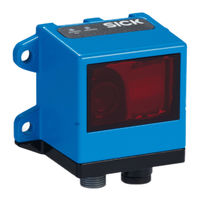
OLM100
SICK OLM100 Manuals
Manuals and User Guides for SICK OLM100. We have
2
SICK OLM100 manuals available for free PDF download: Operating Instructions Manual
SICK OLM100 Operating Instructions Manual (96 pages)
Safe Linear Positioning Safety System
Brand:
SICK
| Category:
Industrial Equipment
| Size: 3 MB
Table of Contents
Table of Contents
3
1 About this Document
7
Purpose of this Document
7
Scope
7
Target Groups and Structure of These Operating Instructions
7
Symbols and Document Conventions
8
Further Information
8
2 Safety Information
9
General Safety Note
9
Intended Use
9
Reasonably Foreseeable Misuse
9
Requirements for the Qualification of Personnel
9
3 Product Description
11
Product Identification
11
Application Description
11
Components of the Safety System
11
Additional Components Required
12
Requirements for Additional Components Required
12
Structure and Function
13
Limits of the Safety System
14
Product Characteristics
15
Safety Functions
15
Safe State
16
4 Project Planning
17
Manufacturer of the Machine
17
Calculating the Performance Level
17
Operating Entity of the Machine
18
Design
18
Integrating the Equipment into the Electrical Control
18
Circuit Diagram
18
Testing Plan
18
Extension and Modification
19
Notes on Fault Detection
20
Illegible Bar Codes
20
Bar Code Gaps
20
5 Mounting
21
Mounting the Sensor Unit
21
Mounting the Bar Code Tape
22
Mounting Flexi Soft
23
6 Electrical Installation
24
General Requirements
24
Connection and Wiring
24
Wiring Principle
24
Safety Controller Pin Assignment
26
Interfaces and Signals
28
Standard Input Interface: Test Signals
28
SSI Interface
29
Signal for PDS (SR) - Drive (Safety-Related)
30
Signal for Optional Safe Brake Control
30
Safe SLS Request Signal
31
Signal for Emergency Stop Pushbutton
31
Signal for Restart Interlock
31
7 Configuration
32
Structure and Application of the Chapter on Configuration
32
Requirements for Software and Firmware
32
Configuration Procedure
32
Pre-Configured Project Files
33
Configuring the Interface for BG100 Motion Sensor
35
Configuring Speed Limits
37
Configuring Position Ranges
40
Assigning Maximum Speeds to the Position Ranges
41
Configuring Safe Cam (SCA)
42
Configuring Stop Ramps
45
Expanding and Modifying the Safety System
49
Configuring Additional Safety Functions
49
External and Internal Signal for Activating the Safely Limited Speed
51
Configuring the Override Function
52
Controlling the Safety Outputs Directly Via PLC
53
Use of Internal Status Information
53
Contents of the CPU Logic
54
Disclaimer Page
54
Interface Page
55
Safe Outputs Page
55
Safe Position and Diagnostics Page
57
Stop/Start/Reset Page
61
Contents of the Motion Control Logic
64
Position_Cross_Check Page
64
Position_Monitor Page
66
Safe Stop Page
69
Notes on the Flexi Soft Logic Editor
71
Creating or Deleting Links
71
Jump Addresses
72
Verification of the Logic
72
Transfer Configuration
72
8 Commissioning
73
Safety
73
Thorough Check
73
9 Operating the Components
74
10 Maintenance of the Components
75
11 Troubleshooting
76
Electromagnetic Compatibility
76
Exchange and Repairs
76
12 Decommissioning
77
Disassembly and Disposal
77
13 Technical Data
78
Data Sheet
78
XTIO Module Inputs
79
Dimensional Drawings
80
Response Times
80
Stopping Time in the Event of a Drive Fault
81
Flexi Soft Cycle Time
81
Maximum Data Reception Interval
82
14 Ordering Information
83
Safe Linear Positioning Ordering Information
83
15 Spare Parts
84
16 Accessories
85
Connectivity
85
17 Annex
86
Checklist for Initial Commissioning and Commissioning
86
Thorough Check of the Requirements Specified in the Operating Instructions for the Safety System
86
Thorough Check of the Hardware Requirements
87
Thorough Check of the Flexi Soft Configuration
88
Thorough Check of the Flexi Soft Documentation
89
Thorough Check on the Process Channel (Standstill)
90
Thorough Check on the Process Channel (Forward Movement)
90
Thorough Check on the Process Channel (Backward Move- Ment)
91
Thorough Check of the Safety Functions
92
Thorough Check of Faults on the Transmission Path
92
Thorough Check for Foreseeable Misuse and Manipulation
93
Advertisement
SICK OLM100 Operating Instructions Manual (56 pages)
Linear measurement sensor
Brand:
SICK
| Category:
Security Sensors
| Size: 2 MB
Table of Contents
Table of Contents
3
About this Document
6
Information on the Operating Instructions
6
Explanation of Symbols
6
Further Information
7
Safety Information
8
Correct Use
8
Improper Use
8
Cybersecurity
8
Limitation of Liability
9
Modifications and Conversions
9
Requirements for Skilled Persons and Operating Personnel
9
Operational Safety and Specific Hazards
10
Hazard Warnings and Operational Safety
10
UL Conformity
11
Function and Use
12
Scope of Delivery
12
Function
12
Type Label
13
Bar Code Tape
14
Control Marks and Configuration Marks
14
Control Marks
14
Configuration Marks
14
Transport and Storage
16
Transport
16
Transport Inspection
16
Storage
16
Mounting
17
Mounting Procedure
17
General Data on the Bar Code Tape
17
Attaching the Barcode Tape
17
Applying Barcode Tape in Horizontal Curves
19
Applying Barcode Tape in Vertical Curves
20
Mounting Instructions
21
Mounting the Device
22
Electrical Installation
25
Safety
25
Wiring Instructions
25
Connecting the Device Electrically
25
Connection Diagrams
26
RS-422 and SSI Connection Diagram
26
Connection Diagram RS-485
26
Canopen Connection Diagram
27
Ethernet Connection Diagram
27
Commissioning
28
Configuring the Device
28
Configuration and Servicing with SOPAS Engineering Tool (SOPAS ET)
28
Parameters for Output of Measured Values
28
Diagnostics
30
Changing the Bar Code Tape Alignment
30
SSI Interface
30
Basics
30
SSI Protocol (Data Formats)
31
RS-422 or RS-485 Interface
32
Protocol Types for Outputting the Position Value
32
Output Rates and Response Times
33
Commands
34
Examples of Commands for Outputting Measurement and Distance Values
35
Examples of Commands for Special Functions
36
Canopen Interface
37
The Canopen Standard
37
Canopen Specific Settings
38
Configuration
38
Output of Measured Values
38
Ethernet Interface
40
Establishing a Connection
40
Protocol Structure
40
Commands with Examples
40
Maintenance
42
Cleaning
42
Maintenance Plan
42
Troubleshooting
43
Warning and Error Messages
43
Returns
44
Repairs
44
Repairing Damage to Bar Code Tape
44
Disposal
45
Technical Data
46
Type-Specific Data
46
Performance
46
Mechanics/Electronics
47
Ambient Data
47
Dimensional Drawing
48
Bar Code Tape
48
Accessories
50
Bar Code Tape
50
Order Notes and Variants of the Bar Code Tape
51
Blank Labels for Repair Codes or Control Marks
53
Sliding Nuts
53
Appendix
54
Declarations of Conformity and Certificates
54
Advertisement
Related Products
SICK OLM200
SICK OLM100-1005S01
SICK OLS10
SICK OLS20
SICK OD1000
SICK OD5000-C85T20
SICK OD5000-C30 Series
SICK OD5000-C30T05
SICK outdoorScan3 EtherNet/IP 2102812
SICK OD2000
SICK Categories
Accessories
Security Sensors
Measuring Instruments
Scanner
Barcode Reader
More SICK Manuals
Login
Sign In
OR
Sign in with Facebook
Sign in with Google
Upload manual
Upload from disk
Upload from URL