Sign In
Upload
Manuals
Brands
SICK Manuals
Controller
MSC800
SICK MSC800 Manuals
Manuals and User Guides for SICK MSC800. We have
1
SICK MSC800 manual available for free PDF download: Operating Instructions Manual
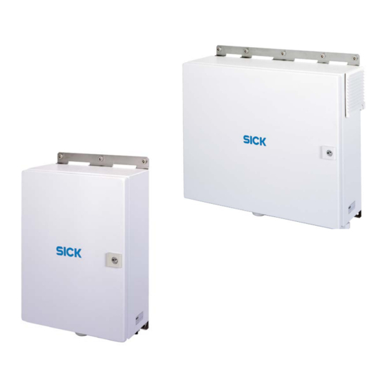
SICK MSC800 Operating Instructions Manual (136 pages)
Modular system controller
Brand:
SICK
| Category:
Controller
| Size: 7 MB
Table of Contents
Table of Contents
3
1 About These Operating Instructions
7
Described Software Version
7
Purpose of this Document
7
Target Group
8
Information Depth
8
Abbreviations Used
8
Symbols Used
10
2 On Safety
12
Authorized Personnel
12
Intended Use
13
General Safety Notes and Protective Measures
13
Standard IP Technology
13
Cyber Security
14
Radio Interference
14
Mounting Work
14
Electrical Installation Work
15
Repairs
15
Quick Stop and Quick Restart
16
Switching off MSC800
16
Switching on MSC800
16
Protecting the Environment
17
Power Consumption
17
Disposal after Final Decommissioning
17
3 Product Description
18
Structure of the MSC800
18
MSC800-1100 Device View
19
MSC800-2100 Device View
20
MSC800-2300 Device View
21
MSC800-3400 Device View
22
MSC800-3600 Device View
23
Scope of Delivery
24
Content of the DVD (No. 2039442)
25
Device Variants
25
System Requirements
26
Mounting Requirements
26
Electrical Installation Requirements
26
Operation Requirements
26
Product Features and Functions (Overview)
27
Operating Principle of the MSC800
28
Object Trigger Control
29
Focus Control
29
Increment Configuration
29
Code Configuration
30
Read Operating Modes
30
Data Processing
32
Output Formats
32
Network
32
Data Interfaces
33
Digital Switching Outputs
33
Relay Switching Outputs
34
Digital Switching Inputs
34
Operating Elements and Displays
34
Operator Interface
34
Function of the Leds
35
4 Mounting
37
Overview of the Mounting Steps
37
Preparation for Mounting
37
Getting the Components to be Mounted Ready
37
Getting the Accessories Ready
37
Selecting the Mounting Location
38
Placement on the Conveyor System
39
Mounting
40
Mounting the MSC800 Control Cabinet Variants
40
Mounting Individual Components of the Logic Unit
40
Mounting of External Components
41
Mounting ID Sensors
41
External Sensors for Triggering
41
Mounting the Incremental Encoder
42
Mounting MLG Light Grid or Vms4Xx/5Xx
42
Dismantling the System
42
5 Electrical Installation
43
Overview of the Installation Steps
43
Electrical Installation of the MSC800
44
Electrical Connections
45
Terminals for Mains Voltage in and Supply Voltage out
45
Electrical Connections on the MSC800-0000 Logic Unit (Overview)
53
Function of the Leds of the Logic Unit
55
Performing the Electrical Installation
56
Wire Cross-Sections
57
Terminal Strips
57
Cable Entries
58
Applying the Shield
59
Circuit Breakers and Fuses
60
DC Supply Voltage for the ICR890 Systems
61
DC 24 V Supply Voltage for CLV490 and Vms4Xx/5Xx
64
HOST/AUX Data Interfaces of the Logic Unit
64
CAN 1/CAN 2 Data Interface of the Logic Unit
65
ETHERNET 1 Ethernet Interface of the Logic Unit
67
IN, TRIGGER, and INC Switching Inputs of the Logic Unit
68
OUT Switching Outputs of the Logic Unit
69
Pin Assignment of the Connections and Assignment of the Wire Color
71
Logic Unit Connections
71
Assignment of Wire Colors of Assembled Cables with Open End
72
6 Commissioning and Configuration
73
Overview of the Commissioning Steps
73
SOPAS-ET Configuration Software
73
Functions of the SOPAS-ET Configuration Software for the MSC800 (Overview)
73
System Requirements for the SOPAS-ET Configuration Software
73
Installing the SOPAS-ET Configuration Software
74
Default for SOPAS-ET Configuration Software
74
Initial Commissioning
75
Overview of the Configuration Steps
75
Establishing Communication with the MSC800
76
Configuring MSC800
77
Loading Amended Parameter Sets into the Logic Unit
77
Saving, Displaying, and Printing Current Parameter Set
78
Default
78
Changing Password
79
Deactivating TCP/IP Cola Protocol Server
80
7 Maintenance
82
Maintenance During Operation
82
Cleaning the MSC800
82
Cleaning Optical Effect Surfaces on Sensors
83
Checking Incremental Encoder
83
Replacing Components of the MSC800
84
Replacing Logic Unit of the MSC800-1100, MSC800-2100, or MSC800-2300
84
Replacing the MSC800 Power Supply Unit Module
85
Replacing the Battery in the Logic Unit
86
Disposal
87
8 Troubleshooting
88
Overview of Potential Errors and Faults
88
Errors During Mounting
88
Error During Electrical Installation
88
Errors During Configuration
88
Faults During Operation
88
Detailed Fault Analysis
89
System Information
89
Status Log
89
SICK Support
89
9 Technical Data
90
MSC800 Data Sheet
90
Dimensional Drawings
92
Dimensional Drawing for the MSC800-1100
92
Dimensional Drawing for the MSC800-2100
93
Dimensional Drawing for the MSC800-2300
94
MSC800-34000/-3600 Dimensional Drawing
95
Circuit Diagrams
96
MSC800-1100 Circuit Diagram
96
MSC800-2100 Circuit Diagram
101
MSC800-2300 Circuit Diagram
106
MSC800-3400 Circuit Diagram
111
MSC800-3600 Circuit Diagram
114
Compliance with EU Directives
117
10 Annex
118
Overview of Annexes
118
Configuration with Command Strings
118
Ordering Information
119
MSC800 Modular System Controller
119
Accessories: Pre-Wired Cables for CAN SENSOR Network
120
Accessories: Male Connector Covers for CLV490 / Vms4Xx/5Xx (CAN SENSOR Network)
121
Accessories: Pre-Wired Cables for Ethernet Connection (MSC800)
121
Accessories: Incremental Encoder (MSC800)
121
Consumables
122
Spare Parts
122
Supplementary Documentation
123
Glossary
124
Figures and Tables
130
List of Tables
130
List of Figures
132
Advertisement
Advertisement
Related Products
SICK MITSUBISHI ELECTRIC MELSEC iQ-F Series
SICK MSL Series
SICK MSLZ Series
SICK MSM Series
SICK MSLE 02-15011
SICK MSLE 03-12211
SICK MSLE 02-15061 A
SICK MSLE 03-12261 A
SICK MSLE 03-14061 A
SICK MSLE 20-10711
SICK Categories
Accessories
Security Sensors
Measuring Instruments
Scanner
Barcode Reader
More SICK Manuals
Login
Sign In
OR
Sign in with Facebook
Sign in with Google
Upload manual
Upload from disk
Upload from URL