Sign In
Upload
Manuals
Brands
Sick Manuals
Media Converter
MAX Series
Sick MAX Series Manuals
Manuals and User Guides for Sick MAX Series. We have
1
Sick MAX Series manual available for free PDF download: Operating Instructions Manual
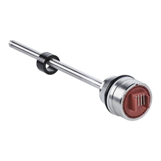
Sick MAX Series Operating Instructions Manual (56 pages)
Linear encoder
Brand:
Sick
| Category:
Media Converter
| Size: 4 MB
Table of Contents
Table of Contents
3
1 About this Document
6
Purpose of this Document
6
Target Audience
6
Further Information
6
Symbols and Document Conventions
6
Warning Levels and Signal Words
6
Information Symbols
6
2 Safety Information
7
General Notes
7
Intended Use
7
Purpose of the Device
7
Responsibility of User
7
3 Product Description
9
Device Variants
9
Product Identification
9
Construction and Function
10
4 Mounting
12
Preparation before Installing the Encoder
12
Installation Cavity for the Linear Encoder
12
Installation Cavity for the Piston and Piston Rod
13
Insertion Chamfer
14
Bore Hole for the Retaining Screw
14
Bore Hole for the Electrical Connection
15
Installation Cavity for the Position Magnet
17
Installing the Position Magnet
17
Installing the Encoder
18
Positioning the O-Ring and Support Ring
18
Insertion in the Cylinder
19
Installation with an M12 Connector System
20
Installation with a Cable Connector and Cable Gland
21
Install the Retaining Screw
22
Cylinder Handling after Encoder Installation
22
Washing and Drying the Cylinder
22
Electrostatic Painting of the Cylinder
23
Mounting the Cylinder on Mobile Hydraulic Machines
23
Electrical and Electrostatic Interference
23
5 Electrical Installation
25
Electrical Connection
25
Connection Diagram, Pin Assignment for 4-Pin M12 Male Connector
25
Cable Connection Diagram
25
Connection Diagram, Pin Assignment for 5-Pin M12 Male Connector
25
Connection Sequence
26
Connection Diagram for Vehicle Electronics
26
6 Commissioning
27
Putting the Encoder into Operation
27
Select a Suitable Fuse
27
Set up the Filter Wiring - Analog
27
Power-Up and Output Signal in the Event of a Fault
27
Bus Termination - Digital
28
Tolerance Considerations for the Set Point
28
CAN Bus Protocols
29
Communication Objects
30
Canopen
30
Sae J1939
31
Configuration and System Startup
31
Configuring Canopen
31
Configuring SAE J1939
33
System Startup for Canopen
34
System Startup for SAE J1939
34
Setting Canopen Operating Parameters
34
Setting SAE J1939 Operating Parameters
36
Canopen Encoder Data During Operation
36
SAE J1939 Encoder Data During Operation
36
Canopen Error Messages
36
SAE J1939 Error Messages
37
7 Maintenance
38
Error Table
38
Checking the Functioning of the Encoder
38
Repairs
39
Testing and Programming
40
8 Transport and Storage
41
Transport and Storage Conditions
41
9 Decommissioning
42
Dismantling
42
Disposal
42
10 Technical Data
43
MAX Analog/Pwm
43
MAX Digital Canopen / SAE J1939
46
Encoder Dimensions
48
Position Magnet Dimensions
49
M12 Flange Dimensions
50
11 Annex
51
Accessories
51
Spare Parts
53
CE Declaration of Conformity
55
Advertisement
Advertisement
Related Products
SICK SK 20.2
Sick MAX30
Sick MAX48
SICK MAX30N
SICK MAX48N
SICK MAX48A
SICK MAXH1A
SICK MAXF1A
SICK senSe2
SICK Smart Sensors KTS
Sick Categories
Accessories
Security Sensors
Measuring Instruments
Scanner
Barcode Reader
More Sick Manuals
Login
Sign In
OR
Sign in with Facebook
Sign in with Google
Upload manual
Upload from disk
Upload from URL