Sign In
Upload
Manuals
Brands
SICK Manuals
Measuring Instruments
EuroFID
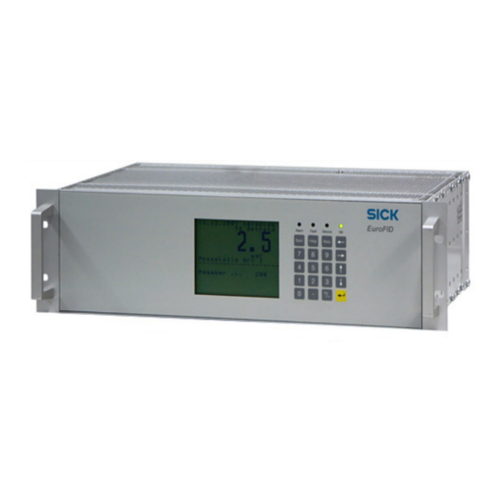
User Manuals: SICK EuroFID Gas Analyzer
Manuals and User Guides for SICK EuroFID Gas Analyzer. We have
1
SICK EuroFID Gas Analyzer manual available for free PDF download: Operating Instructions Manual
SICK EuroFID Operating Instructions Manual (214 pages)
Gas Analyzers for Measurement of the Total Hydrocarbon Content
Brand:
SICK
| Category:
Measuring Instruments
| Size: 3 MB
Table of Contents
Table of Contents
4
1 Important Information
11
Product Identification
12
Main Hazards
13
Main Instructions for Operation
14
Intended Use
15
Purpose of the Device
15
Installation Site
15
Restrictions of Use
16
Responsibility of the User
17
Additional Documents
17
2 Product Description
19
Measuring Principle
20
Measuring Method
20
Measuring Ranges
22
Device Modules
24
Analyzer Units
24
Operating Units
25
Terminal Box
25
Additional Equipment
26
Device Options
26
Accessories
26
3 Project Planning
27
Scope of Delivery
28
Overview of Installation Work
29
Required Resources (Overview)
29
Mechanical Installations (Overview)
30
Mains Connection (Overview)
30
Supply of Operational Gases
31
Screw Connections of the Gas Connections
31
Safety Instructions for Gas Supply
31
Supply of Instrument Air
31
Supply of Fuel Gas
32
Exhaust Gas Connections
32
Exhaust" Gas Connection
32
Bypass" Gas Connection
32
Exhaust Gas Lines
33
Sample Gas Supply
34
Correct Sample Gas Supply
34
Connection of the Sample Gas Line
35
Span Gas Supply ("Calibration Gas" Connection)
36
4 Installation of the Analyzer Unit
37
Installation of the "Wall Housing" Type Analyzer Unit
38
Assembly/Securing
38
Gas Connections
38
Electrical Connections
39
Installation of the "19" Slide-In Enclosure" Type Analyzer Unit
40
Installation/Securing
40
Gas Connections
41
Electrical Connections
41
Installation of the "Inline" Type Analyzer Unit
42
Safety Notes on the Lifting Points
42
Assembly
43
Installing the Hood for Weather Protection
44
Gas Connections
45
Electrical Connections
45
Installation of the Analyzer Unit "Industrial Housing" Type
47
Supplied Condition
47
Assembly
49
Installation of the Industrial Housing
49
Installing the Analyzer
50
Gas Connections
51
Electrical Connections
51
5 Installation of the Terminal Box
53
Installing the Terminal Box
54
Electrical Connections of the Terminal Box
54
6 Installation of the Operating Unit
57
Installing the Operating Unit
58
Mains Connection of the Operating Unit
59
External Mains Switch
59
Mains Cable Connection
59
Signal Connections
60
Overview of Signal Connections
60
Contact Assignment of the Plug Connector "Analog and Digital I/O
61
Analog Outputs
62
Analog Inputs
63
Switching Outputs (Threshold Value Alarm, Status)
64
Control Inputs
65
Printer Connection
66
7 Terminal Modules (Accessory)
67
Terminal Module 1
68
Functions
68
Installation
69
Configuration Options (Jumper)
69
Terminal Assignment
70
Terminal Module 2
72
Functions
72
Technical Design
72
Functional Descriptions
73
Installation
74
Function of the Relay Switching Contacts
74
Configuration Options (Jumper)
74
Signal Connections
76
8 Start-Up
77
Safety Information for Start-Up
78
Preparing for Start-Up
78
Activation Procedure
78
9 Operation (General)
81
Controls and Indicators/Displays
82
Display
82
Leds (Indicators)
82
Keypad
83
Menu System
84
Main Menu
84
Navigation Principle
84
Overview of the Menu System
85
Checking the Operational State (Visual Control)
86
Features of a Safe Operational State
86
Indications of an Unsafe Operational State
86
Behavior in an Emergency
87
10 Main Menu Functions
89
Measurement Display
90
Selecting the Measuring Range
91
Calibration (Note)
91
Flame Ignition
92
Diagnosis
93
Purpose of the Diagnosis Function
93
Activating the Diagnosis Messages
93
Malfunction Messages in the Diagnosis Function
93
Operational Displays in the Diagnosis Function
94
Maintenance (Note)
98
Language (Language Selection)
99
General Help
99
11 "Maintenance" Sub-Menu Functions
101
Accessing the "Maintenance" Sub-Menu
102
Calibration Gas Value (Note)
103
Conversion Factors
104
Setting the Conversion Factor
104
Calculation of Conversion Factors
105
Standby
107
Error Archive
108
Function of the Error Archive
108
Displaying the Error Archive
109
Printing the Error Archive
110
Deleting the Error Archive
111
Filter Change (Menu)
112
System Parameters (Overview)
113
User Level (Activation)
114
Range Select Mode (Measuring Range Selection)
115
Temperature of the Sensor Block
117
I/O Parameters
118
Integrated Value (Averaging for the Measurement Display)
118
Display Rate
119
Setup Filter (Averaging for the "Measured Value" Analog Output)
120
Median Value Time (Averaging for the "Reference Value" Analog Output)
121
Display Range
122
Output Range
123
Range Select Mode (Note)
124
Set Measuring Range (Note)
124
Configuring Threshold Value Alarms
124
Setting the Measuring Ranges
127
Purging Parameters (Purging Time)
128
Device Status "System in Service
129
Threshold Reset
130
Time and Date Settings
131
Setting the Date and Time
131
Changing the Time Zone
132
Summer / Winter Time (Automatic Switchover)
133
Supplementary Text for Physical Unit (Unit of Measurement)
134
Name of Analyzer
135
Printer Functions
136
Paper Format
136
Log Settings
137
Printing Measurement Archive/Average Value Archive
138
Print Instrument Log
139
Print Diagnosis
140
Print Selftest
141
Print All Parameters (Device Data)
142
Restart
143
12 Calibration
145
Introduction to Calibration of the Eurofid
146
Types of Calibration
146
Calibration Gases
147
Zero Gas
147
Span Gas
147
Settings for Calibration
148
Calibration Control
148
Setpoint Value for the Span Gas (Calibration Gas Value)
149
Calibration Times for Automatic Calibration
150
Manual Calibration
151
Checking Calibration
153
Zero Check
153
Sensitivity Test (Calibration Gas Test)
153
13 Shutdown
155
Preparing Shutdown
156
Securing the Connected Systems
156
Protection against Condensation
156
Deactivation Procedure
156
Transport
157
Disposal
157
14 Maintenance
159
Necessary Technical Knowledge for Maintenance Work
160
Safety Instructions for Maintenance Work
160
Maintenance Plan
161
Maintenance by the User
161
Maintenance by the Manufacturer's Service Technicians
161
Servicing the Sample Gas Filter
162
Access to the Sample Gas Filter
162
Replacement/Cleaning of the Filter Element (Procedure)
163
Cleaning the Filter
166
Spare Parts for the Sample Gas Filter
168
15 Clearing Malfunctions
169
If the Eurofid Does Not Work at All
170
If the Measured Values Are Obviously Incorrect
170
Electrical Fuses
171
Mains Fuse of the Operating Unit
171
Fuses in the Analyzer Unit Type "Industrial Housing
171
Fuses in the Terminal Box
172
Overtemperature Protection on the Analyzer Unit
173
Function of the Overtemperature Protection
173
Resetting the Temperature Monitor (after Tripping)
173
Testing the Overtemperature Protection (Note)
174
Malfunction Messages
175
Malfunction Messages on the Display (General)
175
Possible Malfunction Messages
176
16 Technical Data
183
Dimensions
184
Analyzer Units
184
Operating Units
189
Terminal Box
190
Housing Specifications
191
Operating Units
191
Analyzer Units
191
Terminal Box
191
Flange Specification
191
Ambient Conditions
192
Supply Voltage (Mains Voltage)
193
Gas Connections
193
Auxiliary Gases
194
Instrument Air
194
Fuel Gas
195
Sample Gas Conditions
195
Measuring Characteristics
196
Approvals (Suitability Tests)
196
Accessories
197
Mounting Connections
197
Heat Insulation Flange
197
Hood for Weather Protection
198
Shut-Off Fittings
199
Plug Connector for the Operating Unit
200
Terminal Modules
200
Cable
200
17 Older Device Versions
205
Operating Unit - Older Version
206
Terminal Box - Older Version
207
Advertisement
Advertisement
Related Products
SICK EEM37-2 Series
SICK EES37-2KF0A017A
SICK EEM37-2KF0B015A
SICK ES11
SICK EKM36-2 Series
SICK EKM36-2KF0B0S18
SICK EFM50-2KF0A121A
SICK EDM35-2ZF0A0S03
SICK ETL70-0KA4
SICK EKS36-2KF0B018A
SICK Categories
Accessories
Security Sensors
Measuring Instruments
Scanner
Barcode Reader
More SICK Manuals
Login
Sign In
OR
Sign in with Facebook
Sign in with Google
Upload manual
Upload from disk
Upload from URL