Sign In
Upload
Manuals
Brands
Shihlin electric Manuals
DC Drives
SDP-500A4C
User Manuals: Shihlin electric SDP-500A4C DC Drives
Manuals and User Guides for Shihlin electric SDP-500A4C DC Drives. We have
1
Shihlin electric SDP-500A4C DC Drives manual available for free PDF download: Manual
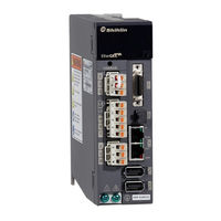
Shihlin electric SDP-500A4C Manual (555 pages)
Brand:
Shihlin electric
| Category:
DC Drives
| Size: 8 MB
Table of Contents
Table of Contents
7
Product Overview and Model Description
14
Outline
14
Product Checklist
14
Product Model Overview
15
Servo Motor Model Naming Rule
15
Servo Drive Model Naming Rule
18
SDP Servo Drive and Motor
19
Servo Drive Appearance and Panel Description
20
Drive Appearance and Panel
20
Servo Drive Appearance and Panel
21
Servo Drive Control Modes Introduction
22
Recommended Breaker and Fuse Specification Table
23
Installation
24
Precautions and Storage
24
Installation Environment
24
Installation Direction and Clearances
25
Wiring and Signal
28
Connection of Power Supply and Peripheral Equipment
28
Peripheral Equipment Wiring Diagram - 200V System
28
Peripheral Equipment Wiring Diagram - 400V System
29
Description of Drive Connectors and Terminals
30
Wiring for Power Supply
32
Specifications for the U,V,W Connectors
34
Wire Selection
38
The Function Diagram of Servo System
40
Wiring for CN1(I/O Signal)
41
CN1 Terminal Diagram
41
CN1 Signal Wire Shielding and Grounding
44
CN1 Terminal Signal Description
46
Interface Wiring Diagram
69
The Specified DI and DO Signal
77
CN2 Encoder Signal Wiring and Description
78
Encoder Connector Specification
79
CN2L Full-Closed Loop/Linear Scale Signal and Wiring Description
83
CN3 Communication Port Signal and Wiring Description
84
CN4 USB Communication Port
85
CN5 Battery Connector of Absolute Encoder
86
Standard Wiring Instruction
87
Position Control Mode(Pr Mode) Wiring Diagram
87
Position Control Mode(Pt Mode) Wiring Diagram
89
Speed Control Mode (S Mode)Wiring Diagram
90
Torque Control Mode (T Mode)Wiring Diagram
91
1PG Wiring Diagram
92
10PG Wiring Diagram
93
10GM Wiring Diagram
94
20GM Wiring Diagram
95
FX3U Wiring Diagram
96
QD75 Wiring Diagram
97
Panel Display and Operation
98
Panel Description
98
Display Procedure
99
Status Display
101
One-Touch Tuning Function
106
Alarm Mode
106
Diagnosis Mode
108
External I/O Signal Indicator
109
DO Forced Output
111
JOG Operation
113
Positioning Test Operation
114
Auto-Offset of Analog Input
116
Inertia Estimation and Tuning by Communication Software
117
Parameter Mode
120
Bit Parameter Setting Instruction
120
Bit Parameter Setting Instruction
121
Other Precautions
125
Running Operation
126
Check Items before Running
126
Test Without Load
127
JOG Test Without Load
127
Positioning Test Without Load
129
Tuning Procedure
131
Tuning Method and Type
131
One-Touch Tuning Function
134
Auto Tuning Function
143
Tuning in Manual Mode
148
Interpolation Mode
150
Position Mode Parameter Setting and Operation
151
Speed Mode Parameter Setting and Operation
153
Torque Mode Parameter Setting and Operation
155
Control Function
157
Selecting the Control Mode
157
Torque Control Mode
158
Analog Torque Command
159
Offset Adjustment of the Analog Torque Command
160
Torque Command Smoothing
161
Torque Limit of Torque Control Mode
162
The Speed Limit of Torque Mode
162
Speed Control Mode
165
Selecting the Speed Command
167
Scaling of the Analog Speed Command
168
Smooth Speed Command
169
Torque Limit of Speed Control Mode
172
Gain Adjustment of the Speed Loop
174
Resonance Suppression Unit
176
Gain Switch Function
182
Position Control Mode
189
External Pulse Command(Pt Command)
191
Internal Position Command (Pr Command)
192
Position Command Smoothing
193
Electronic Gear Ratio
196
Torque Limit of Position Loop
197
Position Loop Gain
198
Dual Control Mode
199
Position/Speed Dual Mode
200
Speed / Torque Dual Mode
201
Torque/Position Dual Mode
202
Other Functions
204
Selection of Regenerative Resistor
204
Analog Monitor Function
209
Operation of Electromagnetic Brake
212
PR (Procedure) Program Control Introductions
215
PR Introduction
215
The Difference between the PR Mode of SDP and SDA
215
DI/DO and Sequences in PR Mode
217
Parameter Setting of PR Mode
219
PR Sequence Status
228
Parameters
234
Parameter Definitions
234
List of Parameters
236
Parameter Group Introduction
272
Communication Function
414
Communication Hardware Interface and Wiring
414
Communication Specifications
417
Modbus Communication Protocol
418
ASCII Mode
418
RTU Mode
424
Write and Read Communication Parameters
430
Troubleshooting
443
Alarm List and Corrective Actions
443
Specifications
467
Servo Drive Standard Specifications
467
Interface and out Dimensions of the Servo Drive
475
Dimensions of Servo Drive
476
Advertisement
Advertisement
Related Products
Shihlin electric SDP Series
Shihlin electric SDP-010A2C
Shihlin electric SDP-020A2C
Shihlin electric SDP-040A2C
Shihlin electric SDP-100A2C
Shihlin electric SDP-150A2C
Shihlin electric SDP-200A2C
Shihlin electric SDP-300A2C
Shihlin electric SDP-200A4C
Shihlin electric SDP-700A4C
Shihlin electric Categories
Inverter
Measuring Instruments
DC Drives
Circuit breakers
Control Panel
More Shihlin electric Manuals
Login
Sign In
OR
Sign in with Facebook
Sign in with Google
Upload manual
Upload from disk
Upload from URL