Sign In
Upload
Manuals
Brands
Servomex Manuals
Measuring Instruments
2500 Series
Servomex 2500 Series Manuals
Manuals and User Guides for Servomex 2500 Series. We have
1
Servomex 2500 Series manual available for free PDF download: Installation Manual
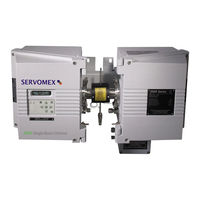
Servomex 2500 Series Installation Manual (80 pages)
Process Gas Analysers
Brand:
Servomex
| Category:
Measuring Instruments
| Size: 0 MB
Table of Contents
Table of Contents
5
Introduction
9
General Description
10
Figure 1.1 2500 Overall View
10
Basic Construction
11
Options and Accessories
12
Heated Sample Cell - Electrical
12
Figure 1.2 2500 Construction
12
Heated Sample Cell - Steam
13
Optional Output Cards
13
Compensation Options
13
Application Options
14
Installation - General
15
Introduction
15
Preparation
15
Tools
15
Safety Precautions
15
Unpacking and Inspection
15
Electrical Connections
16
Installation
17
Positioning
17
Mounting Details
18
Figure 2.1 2500 Positioning Restrictions
19
Figure 2.2 2500 Mounting Details
20
Instructions Specific to Hazardous Area Installations
21
ATEX Label Information
22
Installation - Electrical
25
Electrical Power Connections
25
Figure 3.1A 2500 AC Power and Valve Connections (Purged Filter)
27
Figure 3.1B 2500 AC Power and Valve Connections (Non-Purged Filter)
28
Figure 3.2 2500 Series Terminal Locations
29
Signal Connections
30
Figure 3.3 Signal Cable Connections
30
Analogue Outputs
31
Figure 3.4 SIB and Optional Output Pcb's
31
Table 3.1 Analogue Output Connections
32
Analogue Output Link Selections on Sensor Interface Board (SIB) PCB
33
Relay Outputs
34
Relay Output Link Selection
34
Table 3.2 Relay Output Connections
34
Control Connections
35
Table 3.3 External Control Connections
35
Range Change Input
36
Autocalibration Initiation Input
36
Password Keyswitch Input
36
Sample Flow Sensor Input
37
Solenoid Valve Drives
37
Externally Powered Solenoid Valve Connections
38
Table 3.4 Externally Powered Solenoid Valve Connections
38
Internally Powered Solenoid Valve Connections
39
Table 3.5 Internally Powered Solenoid Valve Connections
39
Digital Connections
40
RS-232 Connection
40
Figure 3.5 Autocalibration Valve Configuration
40
Table 3.6 Serial Data Format
41
Table 3.7 Fault Number Reference
45
Table 3.8 ASCII Characters
46
Table 3.9 RS232 Connections
46
Pressure Transducer Connections - (if Supplied)
47
Table 3.10 Pressure Transducer Connections
47
Figure 3.6 Typical Pressure Transducer Assembly
48
Installation Gas Connections
49
Purge Connections (EU1)
49
General Purge Connections
49
Figure 4.1 Purge Connection Schematic
49
End Boss Purge Connection
51
Introduction
51
End Boss Scrubbers
51
End Boss Vents
52
End Boss Purge
52
Figure 4.2 Cell End Boss Connection
53
Steam Heated Cell
54
Process Stream Connection
54
Basic Operation
54
High Integrity Operation
54
Power-Up
54
Fault Diagnosis and Cell Maintenance
57
Introduction
57
Diagnostics
57
Table 5.1 Diagnostic Displays
58
General Fault Conditions
59
Table 5.2 General Fault Messages
59
Serious Fault (Shutdown) Conditions
61
Cell Maintenance
61
Table 5.3 Serious Fault Displays
61
Figure 5.1 General Cell Construction
62
Routine Leak Checks
65
Spares Lists
67
Spares List
67
General
67
Table 6.1 General Spares List
67
Sample Cell Spares
68
Table 6.2 Sample Cell Spares
68
Source Units
69
Detector Units
69
Table 6.3 Source Unit Spares
69
Table 6.4 Detector Spares
69
Windows
70
Scrubbers
70
Table 6.5 Window Spares
70
Table 6.6 Scrubber Spares
70
Recommended Spares
71
Table 6.7 Recommended Spares
71
Instrument Specifications
73
Generic 2500 Series Performance
73
Environmental Specifications
73
Dimensions
73
Power Supply
73
Table 7.1 General Environmental Specifications
73
Performance Characteristics (each Component)
74
Performance Characteristics - EMC
74
Table 7.2 Performance Characteristics
74
Sample Specification
75
Sample and Ambient Performance
75
Solenoid Valve Relays
75
Table 7.3 Sampling Specification
75
Table 7.4 Sample and Ambient Influence
75
Analogue Outputs
76
Serial Output
76
Inputs
76
Ingress Protection
76
Optical Purge
76
Table 7.5 Serial Output Specification
76
485 Purge Controller (2500 EU1 Only)
77
Alternative Purge Controller (2500 EU1 Only)
77
Table 8.1 02500 Safety Approvals
80
Advertisement
Advertisement
Related Products
Servomex 2700
Servomex SERVOTOUGH LaserExact 2950
Servomex Servotough SpectraScan 2400
Servomex SERVOTOUGH OxyExact 2200 Series
Servomex 2223A
Servomex SERVOTOUGH SpectraExact 2500
Servomex 01440002D
Servomex 07931001B
Servomex 1100A
Servomex 1100H
Servomex Categories
Measuring Instruments
Analytical Instruments
Transmitter
Industrial Equipment
More Servomex Manuals
Login
Sign In
OR
Sign in with Facebook
Sign in with Google
Upload manual
Upload from disk
Upload from URL