Sign In
Upload
Manuals
Brands
Sel Manuals
Other
751A
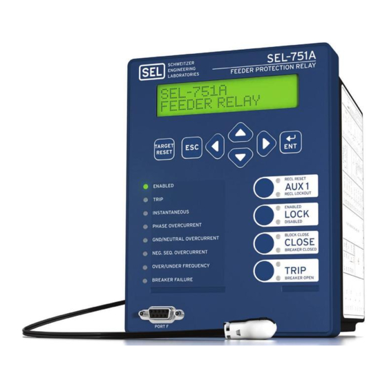
Sel 751A Manuals
Manuals and User Guides for Sel 751A. We have
1
Sel 751A manual available for free PDF download: Instruction Manual
Sel 751A Instruction Manual (641 pages)
Feeder Protection Relay
Brand:
Sel
| Category:
Other
| Size: 9 MB
Table of Contents
Table of Contents
3
List of Tables
7
List of Figures
13
Manual Overview
19
Preface
19
Conventions
20
Typographic Conventions
20
Safety and General Information
21
Symbols
21
Product Labels
22
Laser/Led Emitter
22
SEL-751A LED Information
22
SEL-751A LED Locations
23
Hazardous Locations Approvals
24
Environmental Conditions and Voltage Information
24
Wire Sizes and Insulation
25
Instructions for Cleaning and Decontamination
25
Overview
27
Features
27
Section 1: Introduction and Specifications
27
Models, Options, and Accessories
28
Monitoring Features
28
Communications and Control
28
Table 1.1 Voltage Input Options
29
Accessories
30
Figure 4.42 Voltage
30
Applications
31
Figure 1.1 Typical Current Connections
31
Getting Started
32
Establishing Communication
32
Powering the Relay
32
Checking Relay Status
33
Figure 1.2 Response Header
33
Figure 1.3 STA Command Response-No Communications Card or EIA-232⁄ EIA-485 Communications Card
33
Figure 1.4 STA Command Response-Communications Card/Devicenet Protocol
34
Changing the Time
35
TIM (Time Command)
35
Viewing the Time
35
Table 1.2 SEL-751A Serial Port Settings
33
Changing the Date
34
DAT (Date Command) Viewing the Date
34
Setting the Data and Time
34
Specifications
36
Relay Placement
41
Physical Location
41
Section 2: Installation
41
Overview
41
I/O Configuration
42
Relay Mounting
42
Figure 2.1 Relay Panel-Mount Dimensions
42
Figure 2.2 Slot Allocations for Different Cards
43
Base-Unit Communications Ports (Slot B)
44
Table 2.1 Communication Ports
44
Voltage Card Option
45
Table 2.2 Communication Card Interfaces and Connectors
45
Table 2.3 3 AVI Voltage Card Terminal Designation
45
Enhanced Voltage Card Option with Advanced Metering and Protection Package (5 AVI)
46
Enhanced Voltage Card Option with Monitoring Package
46
Table 2.4 5 AVI Voltage Card Terminal Designation
46
Table 2.5 3 AVI/4 AFDI Voltage Card with Arc-Flash Detection Inputs Terminal Designation
46
Table 2.6 Current Card Terminal Designation
47
Table 2.7 Eight Analog Input (8 AI) Card Terminal Allocation
47
Table 2.8 Four Analog Input/Four Analog Output (4 AI/4 AO) Card Terminal Allocation
47
Table 2.10 RTD (10 RTD) Card Terminal Allocation
48
I/O Card Configuration Procedure
49
Swapping Optional I/O Boards
49
Table 2.11 Four Digital Input/Four Digital Output (4 DI/4 DO) Card Terminal Allocation
49
Table 2.12 Eight Digital Input (8 DI) Card Terminal Allocation
49
Changing Configuration
50
Analog Input Card Voltage/Current Jumper Selection
51
Analog Output (AO) Configuration Jumper
51
Figure 2.3 Circuit Board of Analog I/O Board, Showing Jumper Selection
51
Figure 2.4 JMP1 through JMP4 Locations on 4 AI/4 AO Board
51
Card Layout for Relays with Firmware Versions Earlier than R400
52
Card Layout for Relays with Firmware Versions R400 and Later
52
Password, Breaker Control, and SEL BOOT Jumper Selection
52
Voltage Card Option with Arc-Flash Detection (AFD) Inputs (3 AVI/4 AFDI)
46
I/O (3 DI/4 DO/1 AO) Card Terminal Allocation
48
I/O Input Card
48
RTD (10 RTD) Card Terminal Allocation
48
Figure 2.5 Current Output Jumpers
52
Figure 2.6 Voltage Output Jumpers
52
Table 2.13 Jumper Functions and Default Positions
53
Figure 2.8 Rear-Panel Connections of Selected Cards
54
Rear-Panel and Side-Panel Diagrams
55
Rear-Panel Connections
55
Figure 2.9 Fiber-Optic Serial, Ethernet, EIA-232 Communication, 3 DI/4 DO/1 AO, and 3 AVI Voltage Option
55
Figure 2.10 Fiber-Optic Serial, Ethernet, 8 DI, RTD, and 4 AI/4 AO Option
56
Figure 2.11 Dual Fiber-Optic Ethernet, Fiber-Optic Serial, Devicenet, Fast Hybrid 4 DI/4 DO, and Voltage Option with Monitoring Package
56
Figure 2.12 Fiber-Optic Serial, Ethernet, EIA-232 Communication, 4 DO/3 DI/1AO, and 3 AVI/4 AFDI Voltage Option with Arc-Flash Detector Inputs
57
Ethernet Port
58
Fiber-Optic Serial Port
58
IRIG-B Time-Code Input
58
I/O Diagram
59
Grounding (Earthing) Connections
57
Power Connections
57
Serial Ports
57
Figure 2.13 Control I/O Connections-4 AI/4 AO Option in Slot D and Fiber-Optic Port in Slot B
59
Figure 2.14 Control I/O Connections-Internal RTD Option
59
AC/DC Control Connection Diagrams
60
Fail-Safe/Nonfail-Safe Tripping
60
Figure 2.15 Output OUT103 Relay Output Contact Configuration
60
Figure 2.16 OUT103 Contact Fail-Safe and Nonfail-Safe Options
60
Single Phase-Neutral VT Connection
61
Figure 2.17 Single-Phase Voltage Connections
61
Figure 2.18 Voltage Connections
62
AC/DC Connections and Applications
63
Station DC Battery Monitor
63
Direct Connection
62
Open-Delta VT Connection
62
Wye-Wye VT Connection
62
Figure 2.19 Typical Current Connections
63
Figure 2.20 SEL-751A Provides Overcurrent Protection and Reclosing for a Distribution Feeder (Includes Fast Bus Trip Scheme) (Delta-Connected Pts)
64
Figure 2.21 SEL-751A Provides Overcurrent Protection for a Distribution Bus (Includes Fast Bus Trip Scheme) (Wye-Connected Pts)
65
Figure 2.22 SEL-751A Provides Overcurrent Protection for a Delta-Wye Transformer Bank (Wye-Connected Pts)
66
Figure 2.23 SEL-751A Provides Overcurrent Protection for a Transformer Bank with a Tertiary Winding (Wye-Connected Pts)
67
Figure 2.24 SEL-751A Provides Overcurrent Protection for an Industrial Distribution Feeder (Core-Balance Current Transformer Connected to Channel IN)
68
Arc-Flash Protection: System Installation
69
Light-Sensor Installation
69
Figure 2.25 SEL-751A with an Arc-Flash Option Card and Fiber-Optic-Based Point-Sensor
69
Figure 2.26 Jacketed-Fiber Installation Example
70
Figure 2.27 Connecting Sensor Fibers to the Relay
70
Figure 2.28 Point-Sensor Assembly
70
Figure 2.29 Point-Sensor Installation
71
Figure 2.30 Point-Sensor Directivity (0-360° Around the Mounting Plane)
71
Figure 2.31 Point-Sensor Directivity (Front to Back, above the Mounting Plane)
72
Bare-Fiber Sensor Installation
73
Figure 2.33 Bare-Fiber Sensor Assembly
73
Figure 2.34 Bare-Fiber Sensor Mounting Example
73
Figure 2.35 Bare-Fiber Sensor Components (V-Pin Style)
73
Application Example
74
Figure 2.36 Bare-Fiber Sensor Showing Transition from Bare- to Jacketed-Fiber Section
74
Field Serviceability
75
Figure 2.37 Switchgear Application Example
75
Fuse Replacement
76
Real-Time Clock Battery Replacement
76
Quickset SEL-5030 Software
77
Section 3: PC Software
77
Overview
77
Table 3.1 SEL Software Solutions
77
Setup
78
Figure 3.1 Serial Port Communication Dialog Box
78
Figure 3.2 Serial Port Communication Parameters Dialog Box
79
Figure 3.3 Network Communication Parameters Dialog Box
79
Drivers and Part Number
80
Terminal Logging
80
Terminal Window
80
Figure 3.4 Tools Menu
80
Figure 3.5 Device Response to the ID Command
80
Settings Database Management and Drivers
81
Active Database
81
Database Manager
81
Settings
82
Create a New Database, Copy an Existing Database
82
Settings Editor
82
Figure 3.6 Selection of Drivers
83
Settings Menu
83
Table 3.3 File/Tools Menus
83
Figure 3.7 Update Part Number
84
Figure 3.8 New Setting Screen
84
Access the Expression Builder
85
Entering Settings
85
Expression Builder
85
Settings Editor (Editor Mode)
85
Expression Builder Organization
86
Using the Expression Builder
86
Figure 3.9 Expressions Created with Expression Builder
86
Event Analysis
87
Event Waveforms
87
Text Files
87
Figure 3.10 Composite Screens for Retrieving Events
87
Meter and Control
88
View Event History
88
Get Event
88
View Event Files
88
Figure 3.11 Saving the Retrieved Event
88
Figure 3.12 Device Overview Screen
89
Figure 3.13 Control Screen
90
Figure 3.14 Remote Operation Selection
90
Table 3.4 Help
91
Protection and Logic Functions
93
Section 4: Protection and Logic Functions Overview
94
Application Data
95
Group Settings (SET Command)
95
Table 4.1 Identifier Settings
95
Table 4.2 CT Configuration Settings
95
Table 4.3 Voltage Configuration Settings
96
Basic Protection
97
VNOM Range Check
97
Overcurrent Elements
97
Table 4.4 Maximum Phase Overcurrent Settings
97
Table 4.5 Neutral Overcurrent Settings
98
Figure 4.1 Instantaneous Overcurrent Element Logic
99
Table 4.6 Residual Overcurrent Settings
100
Figure 4.2 Ground Fault Protection Using Core-Balance CT
100
Time-Overcurrent Elemetns
101
Table 4.7 Negative-Sequence Overcurrent Settings
101
Table 4.8 Phase A, B, and C Time-Overcurrent Settings
102
Table 4.9 Maximum Phase Time-Overcurrent
103
Figure 4.3 Phase Time-Overcurrent Elements 51AT, 51BT, and 51CT
103
Table 4.10 Negative-Sequence Time-Overcurrent Settings
104
Figure 4.4 Maximum Phase Time-Overcurrent Elements 51P1T and 51P2T
104
Table 4.11 Neutral Time-Overcurrent Settings
105
Figure 4.5 Negative-Sequence Time-Overcurrent Element 51QT
105
Table 4.12 Residual Time-Overcurrent Settings
106
Figure 4.6 Neutral Time-Overcurrent Elements 51N1T and 51N2T
106
Time-Overcurrent Curves
107
Figure 4.7 Residual Time-Overcurrent Elements 51G1T and 51G2T
107
Relay Word Bit
108
Table 4.13 Equations Associated with U.S. Curves
108
Table 4.14 Equations Associated with IEC Curves
108
Figure 4.8 U.S. Moderately Inverse Curve: U1
109
Figure 4.9 U.S. Inverse Curve: U2
110
Figure 4.10 U.S. very Inverse Curve: U3
111
Figure 4.11 U.S. Extremely Inverse Curve: U4
112
Figure 4.12 U.S. Short-Time Inverse Curve: U5
113
Figure 4.13 IEC Class a Curve (Standard Inverse): C1
114
Figure 4.14 IEC Class B Curve (very Inverse): C2
115
Figure 4.15 IEC Class C Curve (Extremely Inverse): C3
116
Figure 4.16 IEC Long-Time Inverse Curve: C4
117
Figure 4.17 IEC Short-Time Inverse Curve: C5
118
RTD-Based Protection
119
RTD Input Function
119
RTD Location
119
Table 4.15 RTD Settings
119
RTD Trip/Warning Levels
120
RTD Type
120
Table 4.16 RTD Resistance Versus Temperature
120
Voltage-Based Protection
121
Table 4.17 Undervoltage Settings
121
Overvoltage Function
122
Table 4.18 Overvoltage Settings
122
Figure 4.18 Undervoltage Element Logic
123
Figure 4.19 Overvoltage Element Logic
124
Figure 4.20 Synchronism-Check Voltage Window and Slip Frequency Elements
125
Table 4.19 Synchronism-Check Settings
127
Delta-Connected Voltages
128
Synchronism-Check Elements Voltage Inputs
128
System Frequencies Determined from Voltages VA (or VAB for Delta) and VS
128
Block Synchronism-Check Conditions
129
Slip Frequency Calculator
129
Voltage Window
129
Angle Difference Calculator
130
Figure 4.22 Angle Difference between VP and VS Compensated by Breaker Close Time (Fp < Fs and VP Shown as Reference in this Example)
131
Synchronism-Check Element Outputs
132
Power Elements
134
Synchronism-Check Applications for Automatic Reclosing and Manual Closing
134
Synchronism-Check Elements
126
Setting SYNCPH
127
Voltage Input VS Connected Phase-To-Phase or Beyond Delta-Wye Transformer
127
Wye-Connected Voltages
127
Figure 4.23 Three-Phase Power Elements Logic
135
Table 4.20 Power Element Settings
135
Figure 4.24 Power Elements Operation in the Real/Reactive Power Plane
136
Figure 4.25 Power Factor Elements Logic
137
Table 4.21 Power Factor Settings
137
LOP Impact on Other Protection Elements
138
LOP Monitoring and Alarms
138
Loss-Of-Potential (LOP) Protection
138
Frequency Protection
139
Frequency Elements
139
Table 4.22 Frequency Settings
139
Figure 4.26 Loss-Of-Potential (LOP) Logic
139
Rate-Of-Change of Frequency Protection
140
Table 4.23 Rate-Of-Change-Of-Frequency Settings
140
Figure 4.27 Over- and Underfrequency Element Logic
140
Figure 4.28 81R Frequency Rate-Of-Change Scheme Logic
141
Trip/Close Logic
142
Trip/Close Logic Settings
142
Table 4.24 Time Window Versus 81Rntp Setting
142
Table 4.25 Trip/Close Logic Settings
142
Figure 4.29 Trip Logic
143
52A Breaker Status Conditions SEL Control Equation
144
REMTRIP Remote Trip Conditions SEL Control Equation
144
Unlatch Trip Logic
144
CL Close SEL Control Equation
145
Unlatch Close Logic
145
TDURD Minimum Trip Time
143
TR Trip Conditions SEL Control Equation
143
Figure 4.30 Close Logic
145
Reclose Supervision Logic
146
Close Failure Logic
146
Figure 4.31 Reclose Supervision Logic (Following Open Interval Time-Out)
146
Figure 4.32 Reclose Supervision Limit Timer Operation
147
Figure 4.33 SEL-751A Relays Installed at both Ends of a Transmission Line in a High-Speed Reclose Scheme
149
Other Setting Considerations for SEL-751A(1) and SEL-751A(2) Relays
150
SEL-751A(1) Relay
150
SEL-751A(2) Relay
150
Set Reclose Supervision Logic
148
Unlatch Reclose Supervision Logic
149
Reclose Logic
151
Reclosing Relay Open Interval Time-Out
151
Figure 4.34 Reclosing Relay States and General Operation
152
Table 4.27 Reclosing Control Settings
155
Determination of Number of Reclosures (Last Shot)
156
Figure 4.35 Reclosing Sequence from Reset to Lockout with Example Settings
156
Observe Shot Counter Operation
156
Reset Timer
156
Monitoring Open Interval and Reset Timing
157
Setting 79RSD
157
Setting 79RSLD
157
Reclose Initiate and Reclose Initiate Supervision Settings
158
Reclosing Relay Shot Counter
158
Table 4.28 Shot Counter Correspondence to Relay Word Bits and Open Interval Times
158
Additional Settings Example
159
Other Settings Considerations
159
Drive-To-Lockout and Drive-To-Last Shot Settings
160
Factory Settings Example
160
Skip Shot and Stall Open Interval Timing Settings (79SKP and 79STL, Respectively)
161
Block Reset Timing Setting (79BRS)
163
Table 4.26 Relay Word Bit and Front-Panel Correspondence to Reclosing Relay States
152
Lockout State
153
Reclosing Relay States and Settings/ Setting Group Changes
153
Close Logic Can Still Operate When the Reclosing Relay Is Defeated
154
Defeat the Reclosing Relay
154
Open Interval Timers
155
Figure 4.36 Reclose Blocking for Islanded Generator
163
Figure 4.37 Sequence Coordination between the SEL-751A and a Line Recloser
165
Figure 4.38 Operation of SEL-751A Shot Counter for Sequence Coordination with Line Recloser (Additional Settings Example 1)
166
Demand Metering
168
Reclose Supervision Setting (79CLS)
168
Table 4.30 Demand Meter Settings
168
Comparison of Thermal and Rolling Demand Meters
169
Figure 4.40 Demand Current Logic Outputs
169
Figure 4.41 Response of Thermal and Rolling Demand Meters to a Step Input (Setting DMTC = 15 Minutes)
170
Rolling Demand Meter Response
171
Thermal Demand Meter Response
171
Logic Settings (SET L Command)
173
Latch Bits
173
SELOGIC Enables
173
Table 4.31 Enable Settings
173
Figure 4.43 Schematic Diagram of a Traditional Latching Device
174
Figure 4.44 Logic Diagram of a Latch Switch
174
Table 4.33 SEL OGIC Control Equation Operators (Listed in Operator Precedence)
177
Boolean Falling-Edge Operator (F_TRIG)
178
Boolean Rising-Edge Operator (R_TRIG)
178
Figure 4.46 Result of Falling-Edge Operator on a Deasserting Input
178
Math Arithmetic Operators (*, /, +, and –)
178
Boolean Comparison Operators
179
Boolean Equality and Inequality Operators
179
Table 4.34 Other SEL OGIC Control Equation Operators/Values
179
Timers Reset When Power Lost or Settings Changed
179
Sv/Timers Settings
180
Counter Variables
181
Table 4.32 Latch Bits Equation Settings
174
Make Latch Control Switch Settings with Care
175
Nonvolatile State
175
Power Loss
175
Settings Change
175
Boolean NOT Operator
177
Math Negation Operator
177
Parentheses Operator
177
Table 4.36 Counter Input/Output Description
181
Table 4.37 Order of Precedence of the Control Inputs
181
Figure 4.49 Example of the Effects of the Input Precedence
182
Table 4.38 Control Output Equations and Contact Behavior Settings
183
Global Settings (SET G Command)
184
Event Messenger Points
184
Table 4.39 General Global Settings
184
Table 4.40 Event Messenger Settings
184
Figure 4.50 Phase Rotation Setting
184
Synchrophasor Measurement
186
Breaker Failure Setting
186
Table 4.41 Setting Group Selection
186
Table 4.42 Breaker Failure Setting
186
Arc-Flash Protection
187
Arc-Flash Overcurrent Elements
187
Table 4.43 Arc-Flash Overcurrent Settings
187
Figure 4.51 Breaker Failure Logic
187
Table 4.44 Arc-Flash Time-Overlight Settings
188
Figure 4.52 Arc-Flash Instantaneous Overcurrent Element Logic
188
TOL Element Logic Diagram
189
Figure 4.53 Inverse Time-Overlight Element Logic
189
Setting the Arc-Flash Time-Overlight Element
190
Table 4.45 Typical Ambient Illumination Light Levels
190
Figure 4.54 TOL Element Inverse Curve Characteristic
190
Output Logic Programming
191
Analog Inputs
192
Analog Input Calibration Process
192
Analog Input Setting Example
192
Figure 4.55 Analog Input Card Adaptive Name
192
Table 4.46 Summary of Steps
193
Analog (DC Transducer) Input Board
194
Figure 4.56 Settings to Configure Input 1 as a 4-20 Ma Transducer
194
Analog Outputs
195
Table 4.47 Analog Input Card in Slot 3
195
Figure 4.57 Analog Output Number Allocation
195
Station DC Battery Monitor
196
Table 4.48 Output Setting for a Card in Slot 3
196
Figure 4.58 Analog Output Settings
196
Breaker Monitor
197
Digital Input Debounce
197
Figure 4.59 DC Mode Processing
197
Figure 4.60 AC Mode Processing
197
Table 4.49 Slot C Input Debounce Settings
198
Figure 4.61 Timing Diagram for Debounce Timer Operation When Operating in AC Mode
198
Data Reset
199
Access Control
199
Time Synchronization Source
199
Table 4.50 Setting Change Disable Setting
199
Port Settings (SET P Command)
200
Table 4.51 Time Synchronization Source Setting
200
Table 4.52 Front-Panel Serial Port Settings
200
Table 4.53 Ethernet Port Settings
200
Table 4.54 Fiber-Optic Serial Port Settings
201
Table 4.55 Rear-Panel Serial Port (EIA-232) Settings
202
Table 4.56 Rear-Panel Serial Port (EIA-232/EIA-485) Settings
202
Front-Panel Settings (SET F Command)
203
Table 4.57 Rear-Panel Devicenet Port Settings
203
Table 4.58 Display Point and Local Bit Default Settings
203
Boolean Display Point Entry Composition
204
Display Points
204
Table 4.59 LCD Display Settings
204
Hidden (no Display)
205
Table 4.60 Settings that Always, Never, or Conditionally Hide a Display Point
205
Name String, Alias String, and Either Set String or Clear String Only
206
Name, Alias, Set String, and Clear String
206
Table 4.61 Entries for the Four Strings
206
Figure 4.62 Display Point Settings
206
Figure 4.63 Front-Panel Display-Both HV and LV Breakers Open
206
Figure 4.64 Front-Panel Display-HV Breaker Closed, LV Breaker Open
206
Analog Display Point Entry Composition
207
Figure 4.65 Front-Panel Display-Both HV and LV Breakers Closed
207
Figure 4.66 Front-Panel Display-HV Breaker Open, LV Breaker Closed
207
Figure 4.67 Front-Panel Display-HV Breaker Open, LV Breaker Closed
207
Figure 4.68 Front-Panel Display for a Binary Entry in the Name String Only
207
Table 4.62 Binary Entry in the Name String Only
207
Figure 4.69 Front-Panel Display for an Analog Entry in the Name String Only
208
Table 4.63 Analog Entry in the Name String Only
208
Table 4.64 Entry in the Name String and the Alias Strings
208
Figure 4.70 Front-Panel Display for an Entry in (A) Boolean Name and Alias Strings and (B) Analog Name and User Text and Formatting Strings
209
Figure 4.71 Front-Panel Display for an Entry in (A) Boolean Name and Alias Strings and (B) Analog Name, User Text and Formatting Strings, and Engineering Units
209
Table 4.65 Example Settings and Displays
209
Figure 4.72 Adding Temperature Measurement Display Points
210
Figure 4.73 Rotating Display
210
Local Bits
211
Target LED Settings
212
Figure 4.74 Adding Two Local Bits
212
Pushbutton Leds
213
Table 4.66 Target LED Settings
213
Table 4.67 Pushbutton LED Settings
213
Report Settings (SET R Command)
214
SER Chatter Criteria
214
Table 4.68 Auto-Removal Settings
214
Relay Word Bitaliases
215
SER Trigger Lists
215
Table 4.69 SER Trigger Settings
215
Table 4.70 Enable Alias Settings
215
Table 4.71 SET R SER Alias Settings
215
DNP Map Settings (Set DNP N Command, N = 1, 2, or 3)
216
Table 4.72 Event Report Settings
216
Table 4.73 Load Profile Settings
216
Table 4.74 DNP Map Settings
216
Modbus Map Settings (SET M Command)
217
Table 4.75 User Map Register Settings
217
Section 5: Metering and Monitoring
219
Overview
219
Power Measurement Conventions
220
Metering
220
Figure 5.1 Complex Power Measurement Conventions
220
Fundamental Metering
221
Table 5.1 Measured Fundamental Meter Values
221
Thermal Metering
222
Table 5.2 Thermal Meter Values
222
Figure 5.2 METER Command Report with Enhanced Voltage Option with Monitoring Package
222
Energy Metering
223
Table 5.3 RTD Input Status Messages
223
Figure 5.3 METER T Command Report with Rtds
223
Figure 5.4 Device Response to the METER E Command
223
Maximum and Minimum Metering
224
Table 5.4 Maximum/Minimum Meter Values
224
Figure 5.5 Device Response to the METER RE Command
224
Math Variable Metering
225
Figure 5.6 Device Response to the METER M Command
225
Figure 5.7 Device Response to the METER RM Command
225
Figure 5.8 Device Response to the METER MV Command
225
Analog Input Metering
226
RMS Metering
226
Table 5.5 RMS Meter Values
226
Figure 5.9 Device Response to the METER RMS Command
226
Figure 5.10 Device Response to the METER AI Command
226
Arc-Flash Light Intensity Metering
227
Table 5.6 Demand Values
227
Figure 5.11 Device Response to the METER L (Light) Command
227
Figure 5.12 Device Response to the MET de Command
227
Synchrophasor Metering
228
Table 5.7 Synchrophasor Measured Values
228
Figure 5.13 Device Response to the MET PE Command
228
Load Profiling
229
Station DC Battery Monitor
229
Figure 5.14 Device Response to the LDP Command
229
Create Desired Logic for DC Under- and Overvoltage Alarming
230
Figure 5.15 DC Under- and Overvoltage Elements
230
Table 5.8 Station DC Battery Monitor Settings
230
Additional Application
232
Analyze Station DC Battery Voltage
232
Station DC Battery Voltage Dips During Circuit Breaker Tripping
232
View Station DC Battery Voltage
232
Station DC Battery Voltage Dips Anytime
233
Station DC Battery Voltage Dips During Circuit Breaker Closing
233
Breaker Monitor
233
Table 5.9 Breaker Maintenance Information for a 25 Kv Circuit Breaker
234
Table 5.10 Breaker Monitor Settings
234
Figure 5.17 Plotted Breaker Maintenance Points for a 25 Kv Circuit Breaker
235
Breaker Maintenance Curve Details
236
Figure 5.18 SEL-751A Breaker Maintenance Curve for a 25 Kv Circuit Breaker
236
Breaker Monitor Operation Example
237
Figure 5.19 Operation of SEL OGIC Control Equation Breaker Monitor Initiation Setting
237
Figure 5.20 Breaker Monitor Accumulates 10 Percent Wear
238
Figure 5.21 Breaker Monitor Accumulates 25 Percent Wear
239
Figure 5.22 Breaker Monitor Accumulates 50 Percent Wear
240
Figure 5.23 Breaker Monitor Accumulates 100 Percent Wear
241
Breaker Monitor Output
242
Via Front Panel
242
Via Serial Port
242
View or Reset Breaker Monitor Information
242
Determination of Relay Initiated Trips and Externally Initiated Trips
243
Figure 5.24 Input Inxxx Connected to Trip Bus for Breaker Monitor Initiation
243
Section 6: Settings
245
Overview
245
Table 6.1 Methods of Accessing Settings
245
View/Change Settings with Front Panel
246
Figure 6.1 Front-Panel Setting Entry Example
247
View/Change Settings over Communications Port
248
View Settings
248
Enter Settings
248
Table 6.2 SHOW Command Options
248
Table 6.3 SET Command Options
248
Setting Entry Error Messages
249
Table 6.4 SET Command Editing Keystrokes
249
Table 6.5 SET Command Format
249
SEL-751A Settings Sheets
251
Identifier
251
Maximum Phase Overcurrent
251
Neutral Overcurrent
252
Residual Overcurrent
252
Negative-Sequence Overcurrent
253
Phase Time Overcurrent
253
Maximum Phase Time Overcurrent
254
Negative-Sequence Time Overcurrent
255
Neutral Time Overcurrent
255
Residual Time Overcurrent
256
Undervoltage
258
Overvoltage
259
Synchronism Check
259
Power Factor
260
Frequency
260
Rate-Of-Change of Frequency
261
Power
262
Reclosing Control
262
Sv/Timers
265
Counters Equations
268
Math Variables
272
Base Output
273
Slot C Output
274
Slot D Output
274
Slot E Output
274
Phasor Measurement (PMU)
278
Breaker Failure
279
Input Debounce Settings (Base Unit)
285
Input Debounce Settings (Slot C)
285
Input Debounce Settings (Slot D)
286
Input Debounce Settings (Slot E)
286
SET PORT P (P = F, 1, 2, 3, or 4) Command
287
Modbus
292
DNP3 Protocol
292
Mirrored Bits Protocol
293
DNP3 Map Settings (SET DNP N Command)
310
Binary Output Map
313
Analog Input Map
314
Section 7: Communications
319
Overview
319
Table 7.1 SEL-751A Communications Port Interfaces
319
Communications Interfaces
320
Figure 7.1 Simple Ethernet Network Configuration
321
Figure 7.2 Ethernet Network Configuration with Dual Redundant Connections (Failover Mode)
322
Figure 7.3 Ethernet Network Configuration with Ring Structure (Switched Mode)
322
Dual Network Port Operation
323
Failover Mode
323
Fixed Connection Mode
323
Unmanaged Switch Mode
323
NETPORT Selection
324
Port 3 (EIA-232 Option Only)
324
Terminals B01 and B02
324
Figure 7.4 IRIG-B Input (Relay Terminals B01-B02)
324
Figure 7.5 IRIG-B Input Via EIA-232 Port 3 (SEL Communications Processor as Source)
324
Port 2 (Fiber-Optic Serial Port)
325
Figure 7.6 IRIG-B Input VIA EIA-232 Port 3 (SEL-2401/2404/2407 Time Source)
325
Figure 7.7 IRIG-B Input VIA Fiber-Optic EIA-232 Port 2 (SEL-2030/2032 Time Source)
325
Figure 7.8 IRIG-B Input VIA Fiber-Optic EIA-232 Port 2 (SEL-2401/2404/2407 Time Source)
325
+5 VDC Power Supply
326
Connect Your PC to the Relay
326
Port Connector and Communications Cables
326
Table 7.2 EIA-232/EIA-485 Serial Port Pin Functions
326
Figure 7.9 EIA-232 DB-9 Connector Pin Numbers
326
Figure 7.10 SEL Cable C234A-SEL-751A to DTE Device
327
Figure 7.11 SEL Cable C227A-SEL-751A to DTE Device
327
Figure 7.12 SEL Cable C222-SEL-751A to Modem
327
Figure 7.13 SEL Cable C272A-SEL-751A to SEL Communications Processor Without IRIG-B Signal
328
Figure 7.14 SEL Cable C273A-SEL-751A to SEL Communications Processor with IRIG-B Signal
328
Figure 7.15 SEL Cable C387-SEL-751A to SEL-3010
328
Communications Protocols
329
Table 7.3 Protocols Supported on the Various Ports
329
Ethernet Protocols
330
FTP Server
330
SEL ASCII Protocol and Commands
331
Message Format
331
Ping Server
331
Telnet Server
331
Software Flow Control
332
Table 7.4 Serial Port Automatic Messages
332
Table 7.5 Command Response Header Definitions
334
Access Commands (ACCESS and 2ACCESS)
335
Command Explanations
335
Password Requirements
335
Access Levels
333
Access Level Functions
334
Command Summary
334
Table 7.6 Access Commands
335
AFT Command (Arc-Flash Detection Channels Self-Test)
336
Figure 7.16 AFT Command Response
337
Table 7.7 ANALOG Command
337
Table 7.10 CONTROL Command
341
Table 7.11 Three Remote Bit States
341
Table 7.9 COM Command
341
DATE Command (View/Change Date)
342
ETH Command
342
Table 7.8 ANALOG Command Format
337
BRE Command (Breaker Monitor Data)
339
BRE Command (Preload/Reset Breaker Wear)
339
CEV Command
340
CLOSE Command (Close Breaker)
340
COMMUNICATIONS Command
340
CONTROL Command (Control Remote Bit)
341
Table 7.12 COPY Command
342
Table 7.13 COUNTER Command
342
Table 7.14 Date Command
342
Table 7.15 EVENT Command (Event Reports)
343
Table 7.16 EVENT Command Format
343
Figure 7.17 Ethernet Port (PORT 1) Status Report
343
Figure 7.18 Non-Redundant Port Response
343
Table 7.17 FILE Command
344
Table 7.18 GOOSE Command Variants
344
Table 7.19 GROUP Command
346
Figure 7.19 GOOSE Command Response
346
HELP Command
347
Table 7.21 HISTORY Command
347
Table 7.22 IDENTIFICATION Command
347
Table 7.23 IRI Command
347
LDP Command (Load Profile Report)
348
L_D Command (Load Firmware)
348
Table 7.24 LDP Commands
348
Table 7.25 LDP Command Parameters
348
LOOPBACK Command
349
Table 7.26 L_D Command (Load Firmware)
349
MAC Command
350
MET Command (Metering Data)
350
Table 7.28 Meter Command
350
Table 7.29 Meter Command Parameters
350
Table 7.30 Meter Class
350
OPEN Command (Open Breaker)
351
PASSWORD Command (Change Passwords)
351
Table 7.31 PASSWORD Command
351
Table 7.32 PAS Command Format
351
Table 7.33 Factory Default Passwords for Access Levels 1 and 2
351
Table 7.34 Valid Password Characters
352
Figure 7.20 PING Command Response
352
PULSE Command
353
Table 7.35 PUL Outnnn Command
353
Table 7.36 QUIT Command
353
Table 7.37 R_S Command (Restore Factory Defaults)
353
Table 7.38 SER Command (Sequential Events Recorder Report)
353
Table 7.39 SER Command Format
354
Table 7.40 SER D Command
354
Table 7.41 SET Command (Change Settings)
354
SHOW Command (Show/View Settings)
355
Table 7.42 SET Command Format
355
Table 7.43 SET Command Editing Keystrokes
355
Table 7.44 SHOW Command (Show/View Settings)
356
Table 7.45 SHOW Command Format
356
Table 7.46 STATUS Command (Relay Self-Test Status)
357
Figure 7.21 SHOW Command Example
357
Table 7.47 STATUS Command Report and Definitions
358
Figure 7.22 Typical Relay Output for STATUS Command
358
Table 7.48 SUMMARY Command
359
Table 7.49 TARGET Command (Display Relay Word Bit Status)
359
Table 7.50 TARGET Command Format
359
Table 7.51 Front-Panel Leds and the TAR 0 Command
359
Table 7.52 TIME Command (View/Change Time)
360
Table 7.53 TRIGGER Command (Trigger Event Report)
360
Front-Panel Layout
361
Section 8: Front-Panel Operations
361
Overview
361
Human-Machine Interface
362
Contrast
362
Figure 8.1 Front-Panel Overview
362
Access Level 2 Password Entry
363
Figure 8.2 Access Level Security Padlock Symbol
363
Table 8.1 Front-Panel Automatic Messages (FP_AUTO := OVERRIDE)
363
Front-Panel Menus and Screens
364
Front-Panel Timeout
364
Navigating the Menus
364
Figure 8.3 Password Entry Screen
364
Figure 8.4 Front-Panel Pushbuttons
364
Meter Menu
365
Table 8.2 Front-Panel Pushbutton Functions
365
Figure 8.5 Main Menu
365
Figure 8.6 MAIN Menu and METER Submenu
366
Figure 8.7 METER Menu and ENERGY Submenu
366
Figure 8.8 Relay Response When Energy (or Max/Min, Demand, Peak Demand) Metering Is Reset
366
Figure 8.9 Relay Response When no Analog Cards Are Installed
366
Figure 8.10 Relay Response When no Math Variables Enabled
367
Figure 8.11 MAIN Menu and EVENTS Submenu
367
Figure 8.12 EVENTS Menu and DISPLAY Submenu
367
Figure 8.13 Relay Response When no Event Data Available
367
Figure 8.14 Relay Response When Events Are Cleared
367
Figure 8.15 MAIN Menu and TARGETS Submenu
368
Figure 8.16 TARGETS Menu Navigation
368
Figure 8.17 MAIN Menu and CONTROL Submenu
368
Figure 8.18 CONTROL Menu and OUTPUTS Submenu
369
Figure 8.19 CONTROL Menu and LOCAL BITS Submenu
369
Figure 8.20 MAIN Menu and SET/SHOW Submenu
370
Figure 8.21 SET/SHOW Menu
371
Figure 8.22 MAIN Menu and Status Submenu
371
Operation and Target Leds
372
Programmable Leds
372
Figure 8.23 MAIN Menu and Breaker Submenu
372
Figure 8.24 Factory Default Front-Panel Leds
372
Lamp Test
373
Figure 8.25 Target Reset Pushbutton
373
Table 8.3 Possible Warning Conditions (Flashing TRIP LED)
373
Front-Panel Operator Control Pushbuttons
374
Other Target Reset Options
374
Figure 8.26 Operator Control Pushbuttons and Leds
374
Table 8.4 SEL-751A Front-Panel Operator Control Functions
375
Event Reporting
377
Section 9: Analyzing Events
377
Overview
377
Compressed Event Reports
378
Sequential Events Recorder (SER)
378
Length
378
Triggering
378
Event Reporting
378
Event Summaries
379
Figure 9.1 Example Event Summary
379
TRI (Trigger Event Report) Command
379
Table 9.1 Event Types
380
Figure 9.2 Sample Event History
382
Event Report Column Definitions
383
Filtered and Unfiltered Event Reports
383
Currents, Voltages, and RTD Temperatures
381
Event History
381
Event Reports
382
Viewing the Event History
382
Table 9.2 Event Report Current and Voltage Columns
383
Table 9.3 Output, Input, Protection, and Control Element Event Report Columns
384
Example 15-Cycle Event Report
385
Figure 9.3 Example Standard 15-Cycle Event Report 1/4-Cycle Resolution
388
Figure 9.4 Derivation of Event Report Current Values and RMS Current Values from Sampled Current Waveform
389
Figure 9.5 Derivation of Phasor RMS Current Values from Event Report Current Values
390
Sequential Events Recorder (SER) Report
391
SER Triggering
391
SER Aliases
391
Figure 9.6 Example Sequential Events Recorder (SER) Event Report
391
Testing Tools
393
Serial Port Commands
393
Section 10: Testing and Troubleshooting
393
Overview
393
Commissioning Tests
394
Connection Tests
394
Required Equipment
394
Figure 10.1 Three-Phase Wye AC Connections
395
Figure 10.2 Three-Phase Open-Delta AC Connections
396
Functional Tests
397
Phase Current Measuring Accuracy
397
Table 10.1 Serial Port Commands that Clear Relay Data Buffers
397
Current Imbalance Metering Accuracy
398
Table 10.2 Phase Current Measuring Accuracy
398
Table 10.3 Current Unbalance Measuring Accuracy
398
Figure 10.3 Current Source Connections
398
Power and Power Factor Measuring Accuracy
399
Figure 10.4 Wye Voltage Source Connections
399
Table 10.4 Power Quantity Accuracy-Wye Voltages
399
Figure 10.5 Delta Voltage Source Connections
400
Table 10.5 Power Quantity Accuracy-Delta Voltages
400
Arc-Flash Detection (AFD) System Continuous Self-Testing
401
METER LIGHT Report
401
Command AFT (Arc-Flash Test)
402
Testing the Arc-Flash Overcurrent Elements 50PAF and 50NAF
402
Testing the Arc-Flash Time-Over-Light Elements TOL1 to TOL4
402
Testing the Complete Arc-Flash Protection Sytem
402
Periodic Tests (Routine Maintenance)
403
Table 10.6 Periodic Relay Checks
403
Figure 10.6 CEV R Light Event Capture Example
403
Relay Self-Tests
404
Table 10.7 Relay Self-Tests
404
The Relay Does Not Accurately Measure Voltages or Currents
406
The Relay ENABLED Front-Panel LED Is Dark
406
The Relay Front-Panel Display Does Not Show Characters
406
Table 10.8 Troubleshooting
406
Factory Assistance
407
Firmware and Manual Versions
409
Firmware
409
Series Firmware Revision History
409
Appendix A: Firmware and Manual Versions Firmware
410
Upgrade Instructions
419
Appendix B: Firmware Upgrade Instructions
419
Overview
419
Figure B.1 Firmware File Transfer Process
420
SEL Communications Processors
423
SEL Communications Protocols
423
SEL ASCII Commands
423
SEL Compressed ASCII Commands
423
Appendix C: SEL Communications Processors
423
Table C.1 Supported Serial Command Sets
423
Interleaved ASCII and Binary Messages
424
SEL Fast Meter, Fast Operate, and Fast SER
424
Table C.2 Compressed ASCII Commands
424
Figure C.1 SEL Communications Processor Star Integration Network
425
SEL Communications Processor
425
Figure C.2 Multitiered SEL Communications Processor Architecture
426
Table C.3 SEL Communications Processors Protocol Interfaces
426
Developing Star Networks
427
SEL Communications Processor and Relay Architecture
427
Figure C.3 Enhancing Multidrop Networks with SEL Communications Processors
428
Figure C.4 Example of SEL Relay and SEL Communications Processor Configuration
429
SEL Communications Processor Example
429
Table C.4 SEL Communications Processor Port 1 Settings
429
Table C.5 SEL Communications Processor Data Collection Automessages
430
Table C.6 SEL Communications Processor Port 1 Automatic Messaging Settings
430
Table C.7 SEL Communications Processor Port 1 Region Map
430
Relay Metering Data
431
Table C.8 Communications Processor METER Region Map
431
Control Pins
432
Relay Word Bits Information
432
Table C.9 Communications Processor TARGET Region
432
Demand Data
433
Table C.10 Communications Processor DEMAND Region Map
433
DNP3 Specifications
435
Appendix Ddnp3 Communications
435
Overview
435
Introduction to DNP3
435
Data Handling
436
Objects
436
Table D.1 DNP3 Implementation Levels
436
Access Methods
437
Qualifier Codes and Ranges
437
Table D.2 Selected DNP3 Function Codes
437
Binary Control Operations
438
Conformance Testing
438
Table D.3 DNP3 Access Methods
438
DNP3 Serial Network Issues
439
DNP3 LAN/WAN Overview
439
Data Link Layer Operation
439
Network Medium Contention
439
DNP3 in the SEL-751A
440
Data Access
440
Table D.4 TCP/UDP Selection Guidelines
440
Table D.5 DNP3 Access Methods
440
Collision Avoidance
442
Transmission Control
442
Event Data
442
Figure D.2 Message Transmission Timing
442
Binary Controls
443
Table D.6 SEL-751A Event Buffer Capacity
443
Time Synchronization
444
Modem Support
444
Table D.7 Port DNP3 Protocol Settings
445
Table D.8 Serial Port DNP3 Modem Settings
446
Configurable Data Mapping
447
Figure 4.48 Counter
448
Figure D.3 Sample Response to SHO DNP Command
448
Figure D.4 Port MAP Command
449
Table D.9 Sample Custom DNP3 AI Map
451
Figure D.5 Sample Custom DNP3 AI Map Settings
451
AI Point Label, Scaling and Deadband in Acselerator Quickset Software
452
Analog Input Map Entry in Acselerator Quickset Software
452
Figure D.8 Sample Custom DNP3 BO Map Settings
453
Figure D.9 Binary Output Map Entry in AC SEL ERATOR Quickset Software
453
DNP3 Documentation
454
Table D.10 SEL-751A DNP3 Device Profile
454
Table D.11 SEL-751A DNP Object List
455
Table D.12 DNP3 Reference Data Map
459
Table D.13 DNP3 Default Data Map
460
Binary Inputs
461
Binary Outputs
461
Table D.14 Example Object 12 Trip/Close or Code Selection Operation
461
Appendix E: Modbus RTU Communications
463
Overview
463
Communications Protocol
464
Modbus Queries
464
Modbus Responses
464
Supported Modbus Function Codes
464
Table E.1 Modbus Query Fields
464
Table E.2 SEL-751A Modbus Function Codes
464
Modbus Exception Responses
465
Cyclical Redundancy Check
465
Table E.3 SEL-751A Modbus Exception Codes
465
Table E.4 01H Read Discrete Output Coil Status Command
465
Table E.5 Responses to 01H Read Discrete Output Coil Query Errors
466
Table E.6 02H Read Input Status Command
466
Table E.7 02H SEL-751A Inputs
467
03H Read Holding Register Command
470
Table E.8 Responses to 02H Read Input Query Errors
470
Table E.9 03H Read Holding Register Command
471
Table E.10 Responses to 03H Read Holding Register Query Errors
471
Table E.11 04H Read Input Register Command
471
Table E.12 Responses to 04H Read Input Register Query Errors
472
Table E.13 05H Force Single Coil Command
472
Table E.14 01H, 05H SEL-751A Output
472
06H Preset Single Register Command
475
Table E.15 Responses to 05H Force Single Coil Query Errors
475
Table E.16 06H Preset Single Register Command
476
Table E.17 Responses to 06H Preset Single Register Query Errors
476
Table E.18 10H Preset Multiple Registers Command
476
Table E.19 10H Preset Multiple Registers Query Error Messages
477
Table E.20 60H Read Parameter Information Command
477
Table E.21 60H Read Parameter Descriptor Field Definition
477
Table E.22 60H Read Parameter Conversion Field Definition
478
Table E.23 Responses to 60H Read Parameter Information Query Errors
478
Table E.24 61H Read Parameter Text Command
479
Table E.25 61H Read Parameter Text Query Error Messages
479
Table E.26 62H Read Enumeration Text Command
479
Table E.27 61H Read Parameter Enumeration Text Query Error Messages
480
Table E.28 7Dh Encapsulated Packet with Control Command
480
Reading Parameter Information and Value Using Modbus
481
Modifying Relay Settings Using Modbus
481
Table E.29 7Dh Encapsulated Packet Query Errors
481
Table E.30 7Eh NOP Command
481
Controlling Output Contacts Using Modbus
482
User-Defined Modbus Data Region and SET M Command
482
Table E.31 Modbus Register Labels for Use with SET M Command
483
Modbus Register Map
488
Reading History Data Using Modbus
488
Table E.32 Modbus Register Map
488
Appendix Fiec 61850 Communications
545
Features
545
Introduction to IEC 61850
546
Table F.1 IEC 61850 Document Set
546
IEC 61850 Operation
547
Ethernet Networking
547
Object Models
547
Data Mapping
548
Mms
548
Goose
548
Table F.2 Example IEC 61850 Descriptor Components
548
Table F.3 SEL-751A Logical Devices
548
File Services
549
SCL Files
549
Reports
549
Table F.4 Buffered Report Control Block Client Access
550
Figure F.1 SEL-751A Predefined Reports
550
Table F.5 Unbuffered Report Control Block Client Access
551
Figure F.2 SEL-751A Datasets
551
Supplemental Software
552
Time Stamps and Quality
552
GOOSE Processing
553
Figure F.3 GOOSE Quality
553
IEC 61850 Configuration
554
Table F.6 IEC 61850 Settings
554
Acselerator Architect
555
SEL ICD File Versions
555
CID File Conversion
556
Table F.7 ICD Logical Nodes Summary
556
Logical Node Extensions
560
Table F.8 Metering and Measurement Logical Nodes
560
Table F.9 Thermal Metering Data
560
Table F.10 MSTA Class
561
Table F.11 MDST Class
561
Logical Nodes
562
Table F.12 Logical Device: PRO (Protection)
562
Table F.13 Logical Device: MET (Metering)
565
Table F.14 Logical Device: con (Control)
568
Table F.15 Logical Device: ANN (Annunciation)
568
Protocol Implementation Conformance Statement
569
Table F.16 PICS for A-Profile Support
569
Table F.17 PICS for T-Profile Support
569
Table F.18 MMS Service Supported Conformance
569
Table F.19 MMS Parameter CBB
572
Table F.20 Alternate Access Selection Conformance Statement
572
Table F.21 Variableaccessspecification Conformance Statement
572
Table F.22 Variablespecification Conformance Statement
573
Table F.23 Read Conformance Statement
573
Table F.24 Getvariableaccessattributes Conformance Statement
573
Table F.25 Definenamedvariablelist Conformance Statement
573
GOOSE Services Conformance Statement
574
Table F.26 Getnamedvariablelistattributes Conformance Statement
574
Table F.27 Deletenamedvariablelist
574
Table F.28 GOOSE Conformance
574
ACSI Conformance Statements
575
Table F.29 ACSI Basic Conformance Statement
575
Table F.30 ACSI Models Conformance Statement
575
Table F.31 ACSI Services Conformance Statement
576
Devicenet Communications
581
Devicenet Card
581
Appendix G: Devicenet Communications
581
Figure G.1 Devicenet Card Component Overview
581
Features
582
Electronic Data Sheet
583
Appendix H Synchrophasors
585
Overview
585
Synchrophasor Measurement
586
Figure H.1 Phase Reference
586
Figure H.2 Waveform at Relay Terminals May Have a Phase Shift
587
Figure H.3 Correction of Measured Phase Angle
587
Settings for Synchrophasors
588
Table H.1 PMU Settings in the SEL-751A for C37.118 Protocol in Global Settings
588
Descriptions of Synchrophasor Settings
589
Mrate
589
PMSTN and PMID
589
Table H.2 SEL-751A Serial Port Settings for Synchrophasors
589
PHDATAI and ICOMP
590
Table H.3 Synchrophasor Order in Data Stream (Voltages and Currents)
590
Table H.4 User-Defined Analog Values Selected by the NUMANA Setting
591
Table H.5 User-Defined Digital Status Words Selected by the NUMDSW Setting
591
TREA1, TREA2, TREA3, TREA4, and PMTRIG
592
Synchrophasor Relay Word Bits
592
Irigc
592
Table H.6 Synchrophasor Trigger Relay Word Bits
592
View Synchrophasors Using the MET PM Command
593
Table H.7 Time Synchronization Relay Word Bits
593
C37.118 Synchrophasor Protocol
594
Settings Affect Message Contents
594
Communications Bandwidth
594
Figure H.4 Sample MET PM Command Response
594
Protocol Operation
595
Table H.8 Size of a C37.118 Synchrophasor Message
595
Table H.9 Serial Port Bandwidth for Synchrophasors (in Bytes)
595
Transmit Mode Control
596
Message Transmission
597
Appendix I: MIRRORED BITS Communications
597
Overview
597
Operation
597
Message Reception Overview
598
Message Decoding and Integrity Checks
598
Table I.1 Number of MIRRORED BITS Messages for Different Baud
598
Channel Synchronization
599
Loopback Testing
600
Channel Monitoring
600
Settings
601
Table I.4 MIRRORED BITS Communications Message Transmission Period
601
Table I.5 MIRRORED BITS Protocol Settings
601
Table J.1 SEL-751A Relay Word Bits
603
Appendix J: Relay Word Bits Overview
604
Table J.2 Relay Word Bit Definitions for the SEL-751A
606
Appendix K Analog Quantities
617
Table K.1 Analog Quantities
618
Glossary
623
Index
629
SEL-751A Relay Command Summary
633
Advertisement
Advertisement
Related Products
SEL SEL-421
SEL SEL-751A
Sel Categories
Relays
Controller
Control Systems
Control Unit
Power distribution unit
More Sel Manuals
Login
Sign In
OR
Sign in with Facebook
Sign in with Google
Upload manual
Upload from disk
Upload from URL