Sign In
Upload
Manuals
Brands
Secutron Manuals
Fire Alarms
MR-2308-LDR
Secutron MR-2308-LDR Manuals
Manuals and User Guides for Secutron MR-2308-LDR. We have
2
Secutron MR-2308-LDR manuals available for free PDF download: Installation And Operation Manual, Addendum For Installation Instructions
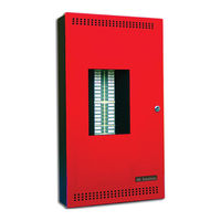
Secutron MR-2308-LDR Installation And Operation Manual (107 pages)
LED Fire Alarm Control Panel
Brand:
Secutron
| Category:
Control Panel
| Size: 1.83 MB
Table of Contents
Table of Contents
3
1 Industry Canada and FCC Notice
9
Notice for All MR-2300 LED Series Built-In Udacts Sold in Canada
9
Industry Canada Notice
9
Notice for All MR-2300 LED Series Built-In Udacts Sold in the U.S.A
9
2 Introduction
11
Overall Features
11
3 Conventions
12
Circuits
12
Zone
12
Display Points
12
Wiring Styles
12
4 System Components
13
Main Fire Control Panel
13
Table 1 MR-2300 LED Series Comparison Chart
13
Relay Module: Twelve Relays
14
Relay Modules: Six Relays
14
Polarity Reversal/City Tie
14
Smart Relay Module
14
Input Class a Converter: Six Circuits
15
Output Class a Converter: Four Circuits
15
Output Class a Converter: Two Circuits
15
Active End-Of-Line Resistors
15
Remote Annunciators
16
Enclosures
16
Additional Fire Alarm System Accessories
17
5 Mechanical Installation
18
Installing the Enclosure
18
Figure 2 Box Dimensions
18
Figure 3 Box Dimensions, Semi-Flush Mounting and Trim Ring
19
Figure 4 Flush Trim Detail (from Above)
19
MMX-BBX-1024DS and MMX-BBX-1024DSR Mechanical Installation
20
Figure 5 MMX-BBX-1024DS and MMX-BBX-1024DSR Installation Instructions and Dimensions
20
Installing the Adder Modules
21
6 Cable and Jumper Connections for Main Board and Adder Modules
22
Main Fire Alarm Board
22
Figure 7 Main Fire Alarm Board Cable Connector and Jumper Settings
22
MR-2300-A Input Class a Converter Adder Module
23
Figure 8 MR-2300-A Input Class a Converter Adder Module
23
MR-2300-NC4/MR-2300-NC2 Output Class a Converter Adder Module
24
Relay Adder Modules
24
Figure 9 MR-2300-NC4/MR-2300-NC2 Output Class a Converter Adder Module
24
Figure 10 MR-2312-R12 Twelve Relay Adder Module
25
Figure 11 MR-2312-R12/MR-2306-R6 Relay Programming
25
MR-2300-PR Polarity Reversal and City Tie Module
26
Figure 12 MR-2306-R6 Six Relay Adder Module
26
Figure 13 Polarity Reversal and City Tie Module
26
Annunciators
27
MR-2312-SR12/MR-2312-SW12 Smart Relay Module
27
MR-2300T Remote Trouble Indicator
27
7 Field Wiring
28
Main Fire Alarm Board Field Wiring
28
Figure 14 Initiating Circuit - Class B Wiring
28
Figure 15 Initiating Circuit- Class a Wiring
29
Figure 16 Indicating Circuit - Class B Wiring
30
Figure 17 Indicating Circuit -Class a Wiring
30
Figure 18 Four-Wire Smoke Detector - Class B Wiring
31
Figure 19 Dialer Wiring
31
Relay Adder Module Wiring
32
Figure 20 Relay Per Zone (MR-2312-R12) Terminal Connection
32
Figure 21 Relay Per Zone (MR-2306-R6) Terminal Connection
32
Connecting to a 3G4010 Interface Device for Canada
33
Figure 22 Connecting an FACP to a 3G4010 Interface Device
33
Connecting to a 3G4010CF Interface Device Outside Canada
34
Figure 23 Connecting an FACP to a 3G4010CF Interface Device Outside Canada
34
Polarity Reversal and City Tie Module (MR-2300-PR) Wiring
35
Figure 24 Polarity Reversal and City Tie Module Terminal Connection
35
Power Supply Connection
36
Figure 25 Power Supply Connection
36
Table 2 Power Supply Ratings
36
Wiring Tables and Information
37
Table 3 Initiating Circuit Wiring
37
Table 4 Indicating Circuit Wiring
37
Four-Wire Smoke Power
38
Supervised Auxiliary Power
38
Auxiliary Power
38
Table 5 RS-485 Wiring to Annunciators and Other Devices
38
8 Turning on the Panel
39
Before Connecting the Power
39
Power-Up Procedure
39
Figure 26 Battery Connections
40
Troubleshooting
41
9 Indicators, Controls and Operations
42
Figure 27 LED Indicators and Control Buttons
42
Common Indicators
43
Indicating Circuit Indicators
46
Figure 28 Alarm Circuit Indicator
46
Table 6 Alarm Circuit Indicators
46
Table 7 Supervisory Circuit Indicators
46
Table 8 Property and Building Safety Indicators
47
Signal Circuit Indicators
48
Common Controls
48
Table 9 Trouble-Only Circuit Indicators
48
Table 10 Signal Circuit Indicators
48
Circuit (Zone) Disconnect Buttons
50
Figure 29 LAMP TEST
50
Common Relays
51
Circuit Types
51
Indicating (Signal) Circuit Types
53
Evacuation Codes (Signal Rates)
53
Single Stage Operation
54
Figure 30 Evacuation and Alert Codes
54
Two-Stage Operation
55
10 Supported Protocols/Devices
57
Synchronous Strobes
57
System Sensor's I3 Devices
57
Figure 31 Open Circuit Trouble
58
Figure 32 Communication Trouble
58
Figure 33 Dirty Device Trouble
58
Figure 34 out of Sensitivity Trouble
58
Figure 35 Freeze Trouble
59
Table 11 I3 Smoke Detector Leds
59
11 Configuration with the CFG-300 LCD Service Tool
60
Table 12 Settings Permitted in CAN/ULCS527
60
Table 13 Settings Permitted in UL864
61
Accessing Configuration Mode
62
Figure 36 MR-2300 Configuration
62
Command Menu
63
Figure 37 Enter Passcode
63
Figure 38 Command Menu
63
MR-2300 Config (Command-Menu)
64
Figure 39 MR-2300 Config Menu
64
Figure 40 Feature Config Menu
65
Table 14 Feature Config Menu
65
Config Info
75
Set Time (Command-Menu)
75
Change Password (Command-Menu)
77
View Event Log (Command-Menu)
77
Figure 41 the Event Log
77
Clear Event Log (Command-Menu)
78
Walk Test (Command-Menu)
78
Figure 42 Select Log
78
Figure 43 Clear All the Selected Logs
78
Figure 44 Logs Cleared
78
Figure 45 Walk Test Confirmation
78
Figure 46 Walk Test Zones
79
Figure 47 Walk Test Active
79
I3 Loop Test (Command-Menu)
80
Figure 48 I3 Loop Test Confirmation
80
Figure 49 I3 Test Zones
80
Figure 50 I3 Test Not Ready
80
Figure 51 the Selected Zone Is Not I3 Type
80
Dialer Config (Command-Menu)
81
Figure 52 Dialer Config Menu
81
Table 15 I3 Detector Statuses
81
Table 16 Auto Test Time and Cellular Report Date
87
Test Dialer (Command-Menu)
89
Exit (Command-Menu)
90
LCD Service Tool Operation
90
Zone Messages
90
Figure 53 Detection Circuit Zone Message
91
Figure 54 Indicating Circuit Zone Message
91
AC Power Fail
92
Battery Trouble
92
Figure 55 AC Power Fail
92
Figure 56 Battery Trouble
92
Ground Fault
93
Remote Annunciator
93
Four-Wire Smoke Detector Supply
93
Figure 57 Ground Fault
93
Figure 58 Remote Annunciator Mismatch Trouble
93
Supervised Aux. Supply
94
City Tie Polarity Reversal - MR-2300-PR/ Relay Module
94
Figure 59 Four-Wire Power Supply
94
Figure 60 Aux. Power Supply
94
Figure 61 City Tie Module Missing
95
Figure 62 City Tie Trouble
95
12 Appendix A: Compatible Receivers
96
13 Appendix B: Reporting
97
Ademco Contact-ID
97
Security Industries Association SIA-DCS
98
14 Appendix C: Specifications
99
Table 17 MR-2300 LED Series Specifications
99
Figure 1 MR-2312-LDR
100
Table 18 MR-2300 LED System Modules and Annunciators
100
15 Appendix D: Power Supply and Battery Calculations
102
16 Appendix E: Auxiliary Devices
103
17 Warranty and Warning Information
104
Advertisement
Secutron MR-2308-LDR Addendum For Installation Instructions (2 pages)
Fire alarm panels backboxes and chassis
Brand:
Secutron
| Category:
Fire Alarms
| Size: 0.05 MB
Advertisement
Related Products
Secutron MR-2312-AT
Secutron MR-2306-DDR
Secutron MR-2320-R
Secutron MR-2308-LR
Secutron MR-2312-LDR
Secutron MR-2312-DDR
Secutron MR-3500 Series
Secutron MMX-2009-12NDS
Secutron MMX-2003-12NDS
Secutron MMX-2017-12NDS
Secutron Categories
Control Panel
Fire Alarms
Smoke Alarm
Control Unit
Accessories
More Secutron Manuals
Login
Sign In
OR
Sign in with Facebook
Sign in with Google
Upload manual
Upload from disk
Upload from URL