Sign In
Upload
Manuals
Brands
Securiton Manuals
Fire Alarms
SecuriFire 500
Securiton SecuriFire 500 Manuals
Manuals and User Guides for Securiton SecuriFire 500. We have
2
Securiton SecuriFire 500 manuals available for free PDF download: Mounting And Installation, System Description
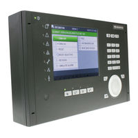
Securiton SecuriFire 500 Mounting And Installation (41 pages)
Brand:
Securiton
| Category:
Control Panel
| Size: 1 MB
Table of Contents
Table of Contents
7
Fig. 1 System Overview of Securifire 500
9
System Overview
9
Securifire 500
11
Securiline Extended
11
Housing Design & Mounting
12
Fig. 2 Inside View of Housing
12
Fig. 3 Rear View of Housing
12
Integrated B7-MIC11 Indication and Control Map
13
Drilling Plan
13
Fig. 4 Front View of Housing
13
Fig. 5 Securifire 500 Drilling Plan
13
Interfaces & Connections
14
B7-CPB11 Main Control Unit
14
System Limits
11
Technical Data
11
Compatibility Notice
14
Fig. 6 B7-CPB11 Main Control Unit
14
Power Supply
15
Interfaces
14
Technical Data
14
Mains Connection
15
Technical Data
15
Fig. 7 Mains Connection
15
Connection of External Consumers
16
Emergency Power Supply (Batteries) Connection X14
16
Technical Data
16
Connection of Relay Outputs to B7-CPB11
17
Technical Data
17
Connection Examples
18
Fig. 8 B7-CPB11, Relay Output (Connection of 230 V Consumers)
18
Fig. 9 B7-CPB11, Relay Output (Siren Connection)
18
Fig. 10 B7-CPB11, Relay Output (Permanent Magnet Connection)
18
Connection of Monitored Inputs and Outputs
19
Technical Data
19
Connection of Inputs to B7-CPB11
20
Fig. 11 B7-CPB11, Quiescent Current Monitored Loads
20
Fig. 12 B7-CPB11, Electronic Loads
20
Fig. 13 B7-CPB11, Connection with Feedback
20
Fig. 14 B7-CPB11, Connection of Inputs
20
EPI Bus for External Indication and Control Maps (X6)
21
Connection of Monitored Outputs to B7-CPB11
20
EPI Bus (X6) Connection
21
Technical Data
21
Securiline Extended
22
Compatibility Information
22
Connection of Securiline Extended Modules
23
Fig. 15 Securiline Extended Connection
23
Securiline Extended (X12) Connection
22
Technical Data
22
Connecting Detector Base USB 501
24
Fig. 16 Stub Line Connection
24
Fig. 17 USB 501 Connection
24
Fig. 18 RAL720X Connection
24
Stub Line Connection
24
Connection of BX-AIM Advanced Input Module
25
Fig. 19 MCP 535X Connection
25
Fig. 20 MCP 545X Connection
25
Fig. 21 BX-AIM, Collective Detector and Monitored Input
25
Fig. 22 BX-AIM, MMD130 Ex-I in Ex Area
25
Connection of MCP 535X and MCP 545X Manual Call Points
25
BX-IM4 Input Module Connection
26
Fig. 23 BX-IM4, Monitored Inputs
26
Fig. 24 BX-IM4, Unmonitored Inputs
26
BX-I2 Input Module Connection
27
Fig. 25 BX-I2, Poll Input and External Voltage
27
Fig. 26 BX-I2, Connection of Special Detectors
27
BX-IOM Input/Output Module Connection
28
Fig. 27 BX-IOM, Consumer with External Voltage Monitoring
28
BX-OI3 Output/Input Module Connection
29
Fig. 28 BX-OI3, Input/Output Module Connection
29
Fig. 29 BX-OI3, Connection of Special Detectors
29
BX-O1 Output Module Connection
30
Fig. 30 BX-O2I4, Output/Input Module Connection
30
Fig. 31 BX-O1, Output Module Connection
30
BX-O2I4 Output/Input Module Connection
30
BX-REL4 Relay Module Connection
31
BX-RGW Radio Module Connection
31
Fig. 32 BX-REL, Relay Module Connection
31
Fig. 33 BX-RGW, Radio Module Connection
31
Connection of the BX-SOL Loop Siren
32
Loop Flashlight BX-FOL Connection
32
Fig. 34 BX-SOL, Loop Siren Connection
32
Fig. 35 BX-FOL, Loop Flashlight Connection
32
Connection of End Switch Module Extended Line BX-ESL
33
Recommended Cable Type for Addressable Loop
33
Fig. 36 BX-ESL, Connection
33
Programming and Software
34
Fig. 37 Securifire Studio
34
Planning
35
Loop Length
35
Current Consumption and Bridging Time
35
Typical Power Consumption Values for B7-CPB11
35
Power Requirement Calculation
35
Battery Current Measurement with a Connected Battery Pair
36
Fig. 38 Battery Current Measurement
36
Commissioning
37
Object-Specific Texts
37
Program
37
Securiline Extended Addressable Loop
37
Contaminated Detector
38
General
38
Possible Causes of Faults
38
Possible Displays & Fault Patterns
38
Simple Troubleshooting
38
Article Numbers / Spare Parts
39
Securifire 500 Fire Alarm Control Panels
39
Securifire Addressable Loop Modules
39
Securifire EPI Devices
40
List of Figures
41
Advertisement
Securiton SecuriFire 500 System Description (20 pages)
fire detection system
Brand:
Securiton
| Category:
Fire Alarms
| Size: 1 MB
Table of Contents
Table of Contents
2
The Securifire System Family
3
Fig.1 Securifire FCP 500
3
The System Concept
4
Fig.2 Overvoltage Protection
4
Securilan
5
Securifire FCP 500
5
Fig.3 Topology of a Securifire 500 Fire Alarm Control Panel
5
Key Features at a Glance
6
Display, Operation and Indication
7
Securifire MIC Indication and Control Maps
7
Fig.4 Securifire FCP with Built-In B7-MIC11 Indication and Control Map
7
External Device Bus
8
Epi-Bus
8
3.2.1.1 B5-EPI-PIM LED Display Panel
8
Fig.5 Schematic of an EPI-BUS
8
Fig.6 B5-EPI-PIM
8
3.2.1.2 B5-EPI-PCM Partial Indication and Control Map
9
3.2.1.3 B5-EPI-FPC Swiss Fire Brigade Panel
9
3.2.1.4 B5-EPI-ASP Fire Brigade Panel for the Netherlands
9
3.2.1.5 B5-EPI-FAT Fire Brigade Indicator Board According with DIN 14662
9
B5-EPI-FPD Fire Brigade Control Board Accroding with DIN 14661
9
Fig.7 B5-EPI-PCM
9
Fig.8 B5-EPI-FPC
9
Fig.9 B5-EPI-ASP
9
Fig.10 B5-EPI-FAT
9
Fig.11 B5-EPI-FPD
9
3.2.1.7 B5-EPI-FPCZ Fire Brigade Panel for the Czech Republic
10
3.2.1.8 B5-EPI-FPS-S Fire Brigade Panel for Sweden
10
Fig.12 B5-EPI-FPCZ
10
Fig.13 B5-EPI-FPS-S
10
Housing Variants and Expansion Options
11
Fig.14 Basic Circuit Board with PSU and Integrated MIC
11
Fig.15 Housing with Operating Panel
11
Housing Variant
11
Mains Connection and Emergency Power Supply
11
Modules
11
Fig.16 Schematic of Securiline Extended Ring Circuit
12
Securiline Extended
12
Key Features at a Glance
13
System Limits
13
Components of the Securiline Extended
14
Fig.17 MCD 573X
14
Fig.18 CCD 573X
14
Fig.19 USB 501
14
Fig.20 LKM 531
14
Fig.21 BX-SOL
14
Fig.22 BX-FOL
14
Fig.23 MCP 545 X N
14
Fig.24 MCP 535
15
Fig.25 BX-OI3
15
Fig.26 BX-O2I4
15
Fig.27 BX-AIM
15
Fig.28 BX-IOM
15
Fig.29 BX-REL4
15
Fig.30 BX-IM4
15
Fig.31 BX-O1
15
Fig.32 BX-I2
16
Fig.33 BX-ESL
16
Download / Upload
17
Loop Configuration
17
Object Texts
17
Programming and Software
17
Projection
17
Loopanalysis
18
Service Tools
18
Servicecenter
18
Servicemonitor
18
Systeminformation
18
Virtual MIC
18
List of Figures
19
Advertisement
Related Products
Securiton SecuriFire FCP 500
Securiton SecuriFire 2000
Securiton SecuriFire 1000
Securiton SecuriFire B6-PSU
Securiton Categories
Smoke Alarm
Control Panel
Power Supply
Remote Control
Water Filtration Systems
More Securiton Manuals
Login
Sign In
OR
Sign in with Facebook
Sign in with Google
Upload manual
Upload from disk
Upload from URL