
Subscribe to Our Youtube Channel
Related Manuals for Securiton SecuriFire 500


Summary of Contents for Securiton SecuriFire 500
- Page 1 SecuriFire 500 Mounting and Installation Technical Description Securiton AG Alpenstrasse 20 3052 Zollikofen Switzerland T 811 065 en...
- Page 3 Users are encouraged to contact the editor/publisher if there are statements which are unintelligible, misleading, incorrect, or if there are errors. © Securiton AG, Alpenstrasse 20, 3052 Zollikofen, Switzerland This document, T 811 065 , is available in the following languages: German...
- Page 4 Safety information Safety information Provided the product is deployed by trained and qualified persons in accordance with technical document T 811 065 and the danger, safety and general information notices in this technical documentation are observed, there is no danger to persons or property under normal conditions and when used properly.
- Page 5 Document history Document history First edition Date 24.10.2012 Mounting and Installation, Technical Description, T 811 065 en 5 / 41...
-
Page 7: Table Of Contents
Contents Contents _________________________________________________________________________________________ System overview Technical data System limits 1.2.1 SecuriFire 500 1.2.2 SecuriLine eXtended _________________________________________________________________________________________ Housing design & mounting Integrated B7-MIC11 indication and control map Drilling plan _________________________________________________________________________________________ Interfaces & connections B7-CPB11 main control unit 3.1.1 Interfaces 3.1.2 Technical data 3.1.3... - Page 8 6.5.2 Contaminated detector 6.5.3 Possible causes of faults _________________________________________________________________________________________ Article numbers / spare parts SecuriFire 500 fire alarm control panels SecuriFire addressable loop modules SecuriFire EPI devices _________________________________________________________________________________________ List of figures 8 / 41 Mounting and Installation, Technical Description, T 811 065 en...
-
Page 9: System Overview
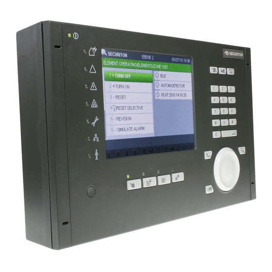
System overview System overview The SecuriFire 500 1-loop small control panel consists of a plastic housing and a B7-MIC11 control panel integrated in the door. Labelling of the control panel is language neutral. The built-in main control unit with integrated power supply unit includes all interfaces for connecting peripherals. The lower area of the housing provides enough space for installing two 7.2 Ah batteries. - Page 10 The earthing concept used in the SecuriFire 500 with central protection earthing to protect persons and electronics requires that all electrically charged components connected to the GND line of the SecuriFire 500 control panel may be installed ex- clusively in areas and buildings which have regulation-complaint potential equalization with this sub-control unit.
-
Page 11: Technical Data
2.5 kg Weight with batteries: 7.8 kg System limits 1.2.1 SecuriFire 500 Main indication and control map (MIC) 1 internal, max. 4 VirtualMIC Interfaces to management systems 4 incl. message server and SMS server External indication and control maps including max. -
Page 12: Housing Design & Mounting
Housing design & mounting The B7-CPB11 main control unit of the SecuriFire 500 contains interfaces for connecting an addressable loop, 2 monitored inputs and outputs for each alarm transmission and transmission unit compliant with EN 54, and 3 relay outputs. The power supply unit is integrated on the main control unit. -
Page 13: Integrated B7-Mic11 Indication And Control Map
Rating plates Each SecuriFire 500 map case is delivered with two rating plates. One of them is already attached at the factory on the right inside in the map case over the batteries. The second rating plate is packaged with the control unit and has to be attached in access level 1 (outside on the map case) before commissioning where it can be easily seen. -
Page 14: Interfaces & Connections
B7-CPB11 main control unit The B7-CPB11 (Controller and Power Supply Board) main control unit is a component of every SecuriFire 500 control panel and includes all interfaces for connecting peripherals, monitored inputs and outputs, service PC and the integrated power supply unit. -
Page 15: Power Supply
(min. 10 A surge resistant) and have its own FI safety switch (U characteristic). Notice Installation of the SecuriFire 500 system components and the mains connection may be performed only by tech- nicians trained specifically for this purpose; installation must always adhere to the applicable rules and regula- tions of the country concerned (e.g. -
Page 16: Emergency Power Supply (Batteries) Connection X14
To ensure the fire alarm system continues to function even when there is a brief interruption of the power supply, two batteries connected in series are built into each SecuriFire 500. If there is a mains failure, they provide the power for the control unit. -
Page 17: Connection Of Relay Outputs To B7-Cpb11
Interfaces & connections 3.2.7 Connection of relay outputs to B7-CPB11 The X5 connector plug on the B7-CPB11 main control unit has 3 freely programmable bistable 240 V/3 A relay contacts for actuating sirens, permanent magnets, relays, etc. With planning software you can define whether the contact is a working contact or normally closed contact. -
Page 18: Connection Examples
Interfaces & connections 3.2.9 Connection examples B7-CPB11 Consumer max. 230V~ / 3A / 300W Fig. 8 B7-CPB11, relay output (connection of 230 V consumers) B7-CPB11 Siren Working contact Fig. 9 B7-CPB11, relay output (siren connection) B7-CPB11 Permanent magnet Normally closed When connecting inductive loads, it is recommended contact to use a freewheel diode (e.g. -
Page 19: Connection Of Monitored Inputs And Outputs
Interfaces & connections Connection of monitored inputs and outputs The X10 connector plug on the B7-CPB11 main control unit is for connecting the transmission unit (main detector) and alarm unit (sirens) for loads between 16 Ω and 1 kΩ. The interface includes two 1.5 A control outputs monitored for short-circuit and wire breakage and 2 monitored inputs. -
Page 20: Connection Of Monitored Outputs To B7-Cpb11
Interfaces & connections 3.3.2 Connection of monitored outputs to B7-CPB11 Quiescent current monitored loads “Electronic loads” B7-CPB11 B7-CPB11 Fig. 11 B7-CPB11, quiescent current monitored loads Fig. 12 B7-CPB11, electronic loads Connection with feedback B7-CPB11 Notice Because of the number of different transmis- sion unit systems, their description is not in- cluded in this document. -
Page 21: Epi Bus For External Indication And Control Maps (X6)
Interfaces & connections EPI bus for external indication and control maps (X6) The EPI bus is a data bus for connecting external indication and control panels. Up to 3 participants can be connected to the EPI bus and operated up to 1 m from the SF500. The following devices can be connected to the X6 interface (EPI bus) of the B7-CPB11 main control unit: Fire brigade control panel Switzerland (B5-EPI-FPC), Fire brigade control panel Germany (B5-EPI-FPD), Fire brigade indicator board (B5-EPI- FAT), Fire brigade control panel Czech Republic (B5-EPI-FPCZ), Fire brigade panel Sweden (B5-EPI-FPS-S), Alarm Scrolling... -
Page 22: Securiline Extended
Interfaces & connections SecuriLine eXtended On the SecuriFire 500 main control unit (B7-CPB11) an addressable loop with associated detectors and modules of the Se- curiLine eXtended technology can be connected. 3.5.1 SecuriLine eXtended (x12) connection Designation Function Screen GND loop end... -
Page 23: Connection Of Securiline Extended Modules
Interfaces & connections Connection of SecuriLine eXtended modules Notice All modules and detectors of the SecuriLine eXtended are fully symmetrical with respect to the input circuit • and short-circuit isolators. When wiring, it is therefore unimportant from which side of the loop “INCOMING” and “OUTGOING”... -
Page 24: Stub Line Connection
Interfaces & connections 3.6.1 Stub line connection Notice According to EN 54, a maximum of 32 detectors (total of automatic + manual detectors) are permitted to be in- stalled on one stub line. B7-CPB 6 5 4 3 2 1 6 5 4 3 2 1 6 5 4 3 2 1 USB 501... -
Page 25: Connection Of Mcp 535X And Mcp 545X Manual Call Points
Interfaces & connections 3.6.3 Connection of MCP 535x and MCP 545x manual call points MCP 545X MCP 545N SHLD SHLD MCP 535X SHLD SHLD Fig. 19 MCP 535x connection Fig. 20 MCP 545x connection 3.6.4 Connection of BX-AIM advanced input module The BX-AIM advanced input module can be used as monitored input for polling potential-free contacts or as detection zone for connecting collective detectors. -
Page 26: Bx-Im4 Input Module Connection
Interfaces & connections 3.6.5 BX-IM4 input module connection The BX-IM4 has 4 primary inputs for polling potential-free contacts. These inputs monitor the lines for creeping wire breakage and short-circuit. The “monitored” or “unmonitored” operation mode is separately planned for each input; further, each input can be programmed inverted. -
Page 27: Bx-I2 Input Module Connection
Interfaces & connections 3.6.6 BX-I2 input module connection The BX-I2 input module has one input for polling a potential-free contact. This input can be planned as element type “input” or “detection zone” and in the “monitored” or “unmonitored” mode. The module also has an opto-isolator input for monitoring a potential-bound signal or an external power supply. Each input can also be programmed inverted. -
Page 28: Bx-Iom Input/Output Module Connection
Interfaces & connections 3.6.7 BX-IOM input/output module connection The BX-IOM has a galvanically isolated output for actuating monitored consumers (e.g. sirens) which are supplied by external voltage sources. The input can be used to poll potential-bound voltage sources. The monitored output is divided into three load ranges and can actuate and monitor a load between 20 Ω... -
Page 29: Bx-Oi3 Output/Input Module Connection
Interfaces & connections 3.6.8 BX-OI3 output/input module connection The BX-OI3 output/input module can be used either as I/O module (1x relay output, 2x monitored input, 1x opto-isolator input) or as detector/detection zone for connecting special detectors. Further information about the BX-OI3 can be found in the data sheet T 131 464. Scan external voltages BX-OI3... -
Page 30: Bx-O2I4 Output/Input Module Connection
Interfaces & connections 3.6.9 BX-O2I4 output/input module connection The BX-O2I4 input/output module can be used either as an I/O module (2 relay outputs, 4 monitored/unmonitored inputs) or as a fire incident control module. Further information about the BX-O2I4 can be found in the data sheet T 811 030. max. -
Page 31: Bx-Rel4 Relay Module Connection
Interfaces & connections 3.6.11 BX-REL4 relay module connection There are four potential-free relay outputs available for switching loads up to 2 A and up to 230 V. All the relays are bistable switchover contacts, and each one has a screw terminal for the normally closed contact and the normally open contact. For each output an “active in fail-safe position”... -
Page 32: Connection Of The Bx-Sol Loop Siren
Interfaces & connections 3.6.13 Connection of the BX-SOL loop siren Further information about connecting and adjusting the BX-SOL loop siren can be found in the data sheet T 800 999. Beginning with SecuriFire version SRP V 1.1, the sound volume can be individually adjusted per loop siren using BX-SOL software. -
Page 33: Connection Of End Switch Module Extended Line Bx-Esl
Interfaces & connections 3.6.15 Connection of end switch module eXtended Line BX-ESL The BX-ESL uses an internal light barrier to determine the position of the activation pin. The state active/passive is reported to the FAS and indicated on the BX-ESL by means of a LED. Further information about the BX-ESL can be found in the data sheet T 131 460. -
Page 34: Programming And Software
All necessary software and system components are available as a “SecuriFire software package” which contains planning, commissioning, maintenance and diagnostics for control units of the SecuriFire 500 system. This SecuriFire software package includes among other things the SecuriFire Studio software (a detailed description of the software is included in the respective documentation). -
Page 35: Planning
1.7 A Power requirement calculation For the SecuriFire 500 power requirement calculation, a power calculation tool is available in which the battery types in use and the necessary bridging time (according to local standards and directives) are entered. Mounting and Installation, Technical Description, T 811 065 en... -
Page 36: Battery Current Measurement With A Connected Battery Pair
If the results of the battery current measurement (example with a 7.2 Ah battery pair) are not in line with the power require- ment calculation (±5%), notify your Securiton Support point immediately. Observe the following procedure precisely: •... -
Page 37: Commissioning
Securiton or by persons expressly authorised to do so by Securiton. Program The SecuriFire 500 is delivered with a simple operating program compliant with EN 54. This program contains all necessary standard parameters required for operating the control panel. Object-specific changes can be programmed with SecuriFire Studio and transferred to the control panel. -
Page 38: Possible Displays & Fault Patterns
Commissioning Possible displays & fault patterns Simple troubleshooting After a successful commissioning, no faults appear on the control panel. As soon as something is not OK, fault patterns may occur. 6.5.1 General Faults are indicated on the indication and control map of the SecuriFire both optically (collective malfunction indication) and audibly (warning sound). -
Page 39: Article Numbers / Spare Parts
Article numbers / spare parts The table below contains only the most important components and spare parts for a SecuriFire 500 fire alarm control panel. Article numbers for detectors, special detectors, peripheral devices, accessories etc. are found in the current product cata- logue for SecuriFire 500. -
Page 40: Securifire Epi Devices
Article numbers / spare parts BX-O2I4 Output/input module 115.246 280 20-2100014-01-01 GEH MOD2 IP66 Map case IP66 for BX-O2I4 403.239 925 FG020235 M20 step nipple MM000181 M16 mounting screw union MM000185 M16 counter-nut MM000186 Warning sticker for 230 V (10 pcs.), available only in German. 3740990 BX-RGW Radio module (incl. -
Page 41: List Of Figures
List of figures List of figures Fig. 1 System overview of SecuriFire 500 .............................. 9 Fig. 2 Inside view of housing ................................12 Fig. 3 Rear view of housing .................................. 12 Fig. 4 Front view of housing ................................. 13 Fig. 5 SecuriFire 500 drilling plan ................................. 13 Fig.
Need help?
Do you have a question about the SecuriFire 500 and is the answer not in the manual?
Questions and answers