Sign In
Upload
Manuals
Brands
Schweitzer Engineering Laboratories Manuals
Relays
SEL-749M
Schweitzer Engineering Laboratories SEL-749M Manuals
Manuals and User Guides for Schweitzer Engineering Laboratories SEL-749M. We have
1
Schweitzer Engineering Laboratories SEL-749M manual available for free PDF download: Instruction Manual
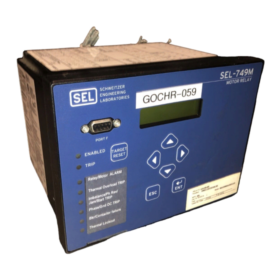
Schweitzer Engineering Laboratories SEL-749M Instruction Manual (314 pages)
Motor Protection Relay
Brand:
Schweitzer Engineering Laboratories
| Category:
Relays
| Size: 4 MB
Table of Contents
Table of Contents
3
List of Tables
7
Preface
15
Manual Overview
15
Conventions
16
Safety and General Information
17
Overview
21
Features
21
Models, Options, and Accessories
23
Applications
24
Getting Started
25
Table 1.1 SEL-749M Serial Port Settings
26
Figure 1.1 Response Header
26
Figure 1.2 STA Command Response-No Communications Card or Communications Card/Modbus RTU Protocol
26
Figure 1.3 STA Command Response-Communications Card/Devicenet Protocol
26
Section 2: Installation
33
Overview
33
Relay Placement
33
I/O Configuration
34
Table 2.1 Slot Allocations for Different Cards
34
Figure 2.1 Relay Panel-Mount Dimensions
34
Table 2.2 Communications Ports
35
Table 2.3 Communications Card Interfaces and Connectors
36
Table 2.4 Voltage Card Terminal Designation
36
Table 2.5 Current Card Terminal Designation
37
Table 2.6 I/O Card (3 DI/4 DO/1 AO) Terminal Allocation
37
Table 2.7 I/O Card (8 DI) Terminal Allocation
37
Rear-Panel Connections
39
Figure 2.2 Rear-Panel Connections of Card Options
39
Figure 2.3 PTC Input, EIA-232/EIA-485 Communications Card, 3 DI/4 DO/1 AO Card, and Voltage Card Options
40
Figure 2.4 IRIG-B Input, Devicenet Card, 3 DI / 4 DO/1 AO Card, and Voltage Card Options
41
Figure 2.5 IRIG-B Input, 8 DI Card, 3 DI /4 DO / 1 AO Card, and Voltage Card Options
42
Table 2.8 PTC Cable Requirements
44
Figure 2.6 Control I/O Connections
44
AC/DC Control Connection Diagrams
45
Table 2.9 Wire-Size Guide
45
Figure 2.7 Output OUT103 Relay Output Contact Configuration
45
Figure 2.8 OUT103 Contact Fail-Safe and Nonfail-Safe Options
46
Figure 2.9 Contactor Application Using Factory Default Settings
46
Figure 2.10 Voltage Connections
47
Figure 2.11 AC Connections with Core-Balance CT
48
Figure 2.12 Control Connections for Failsafe Tripping
48
Figure 2.13 AC Connections for Star-Delta Starting
49
Figure 2.14 Control Connections for Star-Delta Starting
49
Figure 2.15 AC Connections for a Two-Speed Motor-Paralleled Cts
50
Field Serviceability
51
Section 3: PC Software
53
Overview
53
Table 3.1 SEL Software Solutions
53
Table 3.2 AC SEL ERATOR Quickset SEL-5030 Software
53
Setup
54
Figure 3.1 Serial Port Communication Dialog Box
54
Figure 3.2 Serial Port Communication Parameters Dialog Box
54
Terminal
55
Figure 3.3 Tools Menu
55
Figure 3.4 Device Response to the ID Command
55
Settings Database Management and Drivers
56
Settings
57
Table 3.3 File/Tools Menus
58
Figure 3.5 Selection of Drivers
58
Figure 3.6 Update Part Number
59
Figure 3.7 New Setting Screen
59
Figure 3.8 Expressions Created with Expression Builder
61
Event Analysis
62
Figure 3.9 Composite Screens for Retrieving Events
62
Meter and Control
63
Figure 3.10 Saving the Retrieved Event
63
Figure 3.11 Device Overview Screen
64
Figure 3.12 Control Screen
65
Figure 3.13 Remote Operation Selection
65
Available Help
66
Section 4: Protection and Logic Functions
67
Overview
67
Application Data
68
Main Settings (SET Command)
69
Table 4.1 Identifier Settings
69
Table 4.2 CT Configuration and Full Load Current Settings
69
Table 4.3 Voltage Settings
69
Basic Motor Protection
70
Table 4.4 Overload (Thermal Model) Settings
71
Figure 4.1 Thermal Overload Limits (Rating Method)
72
Table 4.5 Thermal Limit Tripping Times in Seconds Vs. Multiples of Full-Load Amps (Service Factor = 1.01)
74
Figure 4.2 Thermal Overload Limits (Curve Method)
74
Table 4.6 Overload Settings (Alarm, Start Inhibit, Cooling, and RTD Bias)
75
Table 4.7 Phase Overcurrent Settings
76
Table 4.8 Neutral Overcurrent Settings
77
Figure 4.3 Overcurrent Element Logic
78
Table 4.9 Residual Overcurrent Settings
79
Table 4.10 Load Jam Settings
79
Figure 4.4 Ground Fault Protection Using Core-Balance CT
79
Table 4.11 Undercurrent Settings
80
Figure 4.5 Load-Jam Element Logic
80
Figure 4.6 Undercurrent (Load-Loss) Logic
80
Table 4.12 Current Imbalance Settings
81
Table 4.13 Protection Disable Settings
82
Table 4.14 Start Monitor Settings
82
Figure 4.7 Current Imbalance Element Logic
82
Table 4.15 Star-Delta Settings
83
Table 4.16 Start Inhibit Settings
83
Figure 4.8 Monitoring Starting Time
83
Table 4.17 Phase Reversal Setting
84
Figure 4.9 Phase Reversal Element Logic
85
PTC/RTD-Based Protection
86
Table 4.18 Speed Switch Settings
86
Figure 4.10 Stalling During Starting
86
Figure 4.11 Speed Switch Logic
86
Voltage-Based Protection
90
Table 4.21 Undervoltage Settings
90
Table 4.22 Overvoltage Settings
90
Figure 4.13 Undervoltage Element Logic
91
Figure 4.14 Overvoltage Element Logic
91
Table 4.24 Underpower Settings
92
Figure 4.15 Reactive Power (VAR) Element Logic
92
Table 4.25 Power Factor Settings
93
Figure 4.16 Underpower Element Logic
93
Figure 4.17 Power Factor Elements Logic
94
Figure 4.18 Loss-Of-Potential (LOP) Logic
95
Frequency and Load Control Settings
96
Table 4.26 Frequency Settings
96
Figure 4.19 Over- and Underfrequency Element Logic
96
I/O Configuration
97
Table 4.27 Load Control Settings
97
Table 4.28 Analog Output Setting
97
Table 4.29 Scaling of Analog Output
98
Table 4.30 Trip Inhibit Settings
98
Table 4.31 Trip and Close Logic Settings
99
Figure 4.20 Stop/Trip Logic
100
Figure 4.21 Thermal Element Lockout Logic
101
Table 4.32 Motor Control Settings
102
Figure 4.22 Motor State Logic
102
Figure 4.23 Start Logic
103
Logic Settings (SET L Command)
104
Table 4.33 Settings Selected by SPEED2 Input
104
Table 4.34 SEL OGIC Enable Settings
104
Table 4.35 Latch Bits Equations Settings
104
Table 4.37 Control Output Equations and Contact Behavior Settings
105
Global Settings (SET G Command)
106
Table 4.38 General Global Settings
106
Table 4.39 Target Reset Setting
106
Table 4.40 Setting Change Disable Setting
106
Figure 4.24 Phase Rotation Setting
106
Port Settings (SET P Command)
107
Table 4.41 Front-Panel Serial Port F Settings
107
Table 4.42 Rear-Panel Serial Port 3 Settings
107
Table 4.43 Rear-Panel Serial Port 4 Settings
107
Front-Panel Set (SET F Command)
108
Table 4.44 Rear-Panel Devicenet Port Settings
108
Table 4.45 General LCD Display Settings
108
Table 4.46 Display Enable Settings
109
Table 4.47 Target LED Settings
109
Report Settings (SET R Command)
110
Table 4.48 SER Trigger Settings
110
Table 4.49 Event Report Settings
110
Logic Functions
111
Table 4.50 Motor Start Report Setting
111
Table 4.51 SEL-749M Logic Inputs and Outputs
111
Figure 4.25 Example Operation of Optoisolated Inputs IN101-IN102
112
Figure 4.26 Example Operation of Optoisolated Inputs IN401-IN403
112
Figure 4.27 Remote Control Switches Drive Remote Bits RB1-RB8
113
Figure 4.28 Traditional Latching Relay
114
Figure 4.29 Latch Control Switches Drive Latch Bits LT01-LT08
114
Table 4.52 Operator Precedence
116
Figure 4.32 Factory Default Contact Output OUT101 Operation
117
Section 5: Metering and Monitoring
119
Overview
119
Metering
119
Table 5.1 Measured Values
120
Table 5.2 Thermal Meter Values
120
Table 5.3 RTD Input Status Messages
121
Figure 5.1 METER Command Report with Voltage Option
121
Figure 5.2 METER T Command Report with Rtds
121
Power Measurement Conventions
122
Figure 5.3 Complex Power Measurement Conventions-Motor Action
122
Motor Operating Statistics
123
Figure 5.4 MOTOR Command Example
123
Motor Start Report
124
Motor Start Trending
125
Figure 5.5 Motor Start Report Example
125
Figure 5.6 Motor Start Trending Report Example
126
Section 6: Settings
127
Overview
127
Table 6.1 Methods of Accessing Settings
127
View/Change Settings Using the Front Panel
128
Figure 6.1 Front-Panel Setting Entry Example
129
View/Change Settings with Serial Port
130
Table 6.2 SHOW Command Options
130
Table 6.3 SET Command Options
130
Setting Entry Error Messages
131
Table 6.4 SET Command Editing Keystrokes
131
Table 6.5 SET Command Format
131
Table 6.6 Setting Interdependency Error Messages
132
SEL-749M Settings Sheets
133
Section 7: Communications
149
Overview
149
Communications Interfaces
149
Table 7.1 SEL-749M Port Interfaces
149
Table 7.2 EIA-232/EIA-485 Serial Port Pin Functions
151
Figure 7.1 EIA-232 DB-9 Connector Pin Numbers
151
Figure 7.2 SEL Cable C234A-SEL-749M to DTE Device
151
Figure 7.3 SEL Cable C227A-SEL-749M to DTE Device
152
Figure 7.4 SEL Cable C222-SEL-749M to Modem
152
Figure 7.5 SEL Cable C272A. SEL-749M to SEL Communications Processor (Without IRIG-B Signal)
152
Figure 7.6 SEL Cable C273A. SEL-749M to SEL Communications Processor (with IRIG-B Signal)
152
Communications Protocol
153
Table 7.3 PROTO Setting and Command Sets
153
Figure 7.7 Port 4A EIA-485 Serial Port Connections
153
SEL ASCII Protocol Details
154
Table 7.4 Serial Port Automatic Messages
155
Table 7.5 Command Response Header
157
Table 7.6 Access Commands
158
Table 7.8 ANALOG Command Format
159
Table 7.9 BNAMES Command
160
Table 7.11 CEVENT Command (Compressed Event Report)
161
Table 7.12 CEVENT Command Format
161
Table 7.13 CHISTORY Command (Compressed History)
161
Table 7.14 CHISTORY Command Format
161
Table 7.15 CONTROL Command
162
Table 7.16 CONTROL Subcommands
162
Table 7.17 CSTATUS Command (Compressed Status)
162
Table 7.18 CSUMMARY Command
162
Table 7.21 EVENT Command (Event Reports)
163
Table 7.22 EVENT Command Format
163
Table 7.24 HISTORY Command
164
Table 7.25 IDENTIFICATION Command
164
Table 7.26 IRI Command
164
Table 7.27 L_D Command (Load Firmware)
165
Table 7.28 METER K (Instantaneous Metering)
165
Table 7.29 METER T (Thermal and RTD Metering)
166
Table 7.30 MOTOR Command
166
Table 7.31 MSR (Motor Start Report) Command
167
Table 7.32 MST (Motor Start Trend) Command
167
Table 7.33 PASSWORD Command
167
Table 7.34 PAS Command Format
167
Table 7.35 Factory Default Passwords for Access Levels 1 and 2
168
Table 7.36 Valid Password Characters
168
Table 7.37 QUIT Command
168
Table 7.38 R_S Command (Restore Factory Defaults)
169
Table 7.39 SER Command (Sequential Events Recorder Report)
169
Table 7.40 SER Command Format
169
Table 7.41 SET Command (Change Settings)
170
Table 7.42 SET Command Format
170
Table 7.43 SET Command Editing Keystrokes
170
Table 7.44 SHOW Command (Show/View Settings)
171
Table 7.45 SHOW Command Format
171
Figure 7.8 SHOW Command Example
171
Table 7.46 SNS Command
172
Table 7.47 STATUS Command (Relay Self-Test Status)
172
Table 7.48 STATUS Command Report and Definitions
172
Figure 7.9 STATUS Command Example
173
Table 7.49 STOP Command
174
Table 7.50 STR Command
174
Figure 7.10 Typical Relay Output for STATUS Command
174
Table 7.52 TARGET Command (Display Relay Word Bit Status)
175
Table 7.53 TARGET Command Format
175
Table 7.54 Front-Panel Leds and the TAR 0 Command
175
Figure 7.11 SUMMARY Command Example
175
Table 7.55 TIME Command (View/Change Time)
176
Table 7.56 TRIGGER Command (Trigger Event Report)
176
Section 8: Front-Panel Operations
177
Overview
177
Front-Panel Layout
177
Figure 8.1 Front-Panel Pushbuttons-Overview
177
Human-Machine Interface
178
Table 8.1 Front-Panel Automatic Messages
178
Figure 8.2 Access Level Security Padlock Symbol
179
Figure 8.3 Password Entry Screen
179
Table 8.2 Front-Panel Pushbutton Functions
180
Figure 8.4 Front-Panel Pushbuttons
180
Figure 8.5 SEL-749M Front-Panel Menu Structure (Continued)
181
Figure 8.6 RELAY Heading Example
184
Operation and Target Leds
185
Figure 8.7 Factory Default Front-Panel Leds
185
Table 8.3 Possible Warning Conditions (Flashing TRIP LED)
186
Section 9: Analyzing Events
189
Overview
189
Event Reporting
190
Table 9.1 Event Types
192
Figure 9.1 Example Event Summary
192
Figure 9.2 Sample Event History
194
Table 9.2 Event Report Current and Voltage Columns
195
Table 9.3 Output, Input, and Protection, and Control Element Event Report Columns
196
Figure 9.3 Example Standard 15-Cycle Event Report 1/4-Cycle Resolution
199
Figure 9.4 Derivation of Event Report Current Values and RMS Current Values from Sampled Current Waveform
200
Figure 9.5 Derivation of Phasor RMS Current Values from Event Report Current Values
201
Sequential Events Recorder (SER) Report
202
Table 9.4 Example SER Event Report Explanation
202
Figure 9.6 Example Sequential Events Recorder (SER) Event Report
202
Section 10: Testing and Troubleshooting
203
Overview
203
Testing Tools
203
Table 10.1 Resultant Scale Factors for Inputs
204
Figure 10.1 Low-Level Test Interface (J2 and J4)
204
Commissioning Tests
205
Figure 10.2 Three-Phase Wye AC Connections
207
Figure 10.3 Three-Phase Open-Delta AC Connections
207
Table 10.2 Serial Port Commands that Clear Relay Data Buffers
208
Table 10.3 Phase Current Measuring Accuracy
209
Figure 10.4 Current Source Connections
209
Table 10.4 Current Unbalance Measuring Accuracy
210
Figure 10.5 Wye Voltage Source Connections
210
Table 10.5 Power Quantity Accuracy-Wye Voltages
211
Figure 10.6 Delta Voltage Source Connections
211
Periodic Tests (Routine Maintenance)
212
Table 10.6 Power Quantity Accuracy-Delta Voltages
212
Table 10.7 Periodic Relay Checks
212
Self-Test
213
Table 10.8 Relay Self-Tests
213
Troubleshooting
215
Factory Assistance
215
Table 10.9 Troubleshooting
215
Table A.1 Firmware Revision History
217
Appendix A: Firmware and Manual Versions Firmware
218
Instruction Manual
219
Table A.2 Instruction Manual Revision History
219
Appendix B: Firmware Upgrade Instructions
221
Overview
221
Upgrade Instructions
221
Figure B.1 Firmware File Transfer Process
222
Table C.1 Supported Serial Command Sets
225
Appendix C: SEL Communications Processors SEL Communications Protocols
226
Table C.2 Compressed ASCII Commands
226
SEL Communications Processor
227
Figure C.1 SEL Communications Processor Star Integration Network
227
Table C.3 SEL Communications Processors Protocol Interfaces
228
Figure C.2 Multitiered SEL Communications Processor Architecture
228
SEL Communications Processor and Relay Architecture
229
Figure C.3 Enhancing Multidrop Networks with SEL Communications Processors
230
SEL Communications Processor Example
231
Table C.4 SEL Communications Processor Port 1 Settings
231
Table C.5 SEL Communications Processor Data Collection Automessages
231
Figure C.4 Example of SEL Relay and SEL Communications Processor Configuration
231
Table C.6 SEL Communications Processor Port 1 Automatic Messaging Settings
232
Table C.7 SEL Communications Processor Port 1 Region Map
232
Table C.8 Communications Processor METER Region Map
232
Table C.9 Communications Processor TARGET Region
233
Appendix D: Modbus RTU Communications Protocol
235
Overview
235
Communications Protocol
235
Table D.1 Modbus Query Fields
235
Table D.2 SEL-749M Modbus Function Codes
236
Table D.3 SEL-749M Modbus Exception Codes
236
Table D.4 03H Read Holding Register Command
237
Table D.5 Responses to 03H Read Holding Register Query Errors
237
Table D.6 04H Read Input Register Command
238
Table D.7 Responses to 04H Read Input Register Query Errors
238
Table D.8 06H Preset Single Register Command
238
Table D.9 Responses to 06H Preset Single Register Query Errors
238
Table D.10 10H Preset Multiple Registers Command
239
Table D.11 10H Preset Multiple Registers Query Error Messages
239
Table D.12 60H Read Parameter Information Command
239
Table D.13 60H Read Parameter Descriptor Field Definition
240
Table D.14 60H Read Parameter Conversion Field Definition
240
Table D.15 Responses to 60H Read Parameter Information Query Errors
241
Table D.16 61H Read Parameter Text Command
241
Table D.17 61H Read Parameter Text Query Error Messages
241
Table D.18 62H Read Enumeration Text Command
242
Table D.19 61H Read Parameter Enumeration Text Query Error Messages
242
Table D.20 7Dh Encapsulated Packet with Control Command
242
Table D.21 7Dh Encapsulated Packet Query Errors
243
Table D.22 7Eh NOP Command
243
Modbus Register Map
245
Table D.23 Modbus Register Map
245
Table 4.19 PTC Settings
267
Table 4.20 RTD Settings
267
Table 4.23 VAR Settings
268
Appendix E Devicenet
271
Overview
271
Devicenet Card
271
Figure E.1 SEL-749M Motor Relay Back Panel View with Devicenet
271
Features
272
Figure E.2 Devicenet Card Component Overview
272
Electronic Data Sheet
273
Appendix F Motor Thermal Element
275
Overview
275
Purpose of Motor Thermal Protection
276
The Basic Thermal Element
277
Figure F.1 Motor Thermal Limit Characteristic Plotted with Motor Starting Current
277
Figure F.2 Electrical Analog of a Thermal System
277
Figure F.3 Typical Induction Motor Current, Torque, and Rotor Resistance Versus Slip
278
Motor Starting Protection
280
Figure F.4 Motor Starting Thermal Element
280
Motor Running Protection
281
Figure F.5 Motor Running Thermal Element with Resistance and Trip Level Undefined
281
Figure F.6 Calculating the Normal Operating Energy by Using Locked Rotor Trip Times
281
Interpreting Percent Thermal Capacity Values
283
Thermal Element Trip-Time Equations
283
Appendix G Relay Word Bits
287
Overview
287
Table G.1 SEL-749M Relay Word Bits
287
Definitions
288
Table G.2 Relay Word Bit Definitions for the SEL-749M
288
Glossary
295
Index
301
Table 7.7 ANALOG Command
301
Table 7.10 CASCII Command
301
Table 7.19 Date Command
302
Table 7.20 DNAMES Command
302
Table 7.23 FILE Command
302
Table 7.51 SUMMARY Command
302
SEL-749M Relay Command Summary
307
Advertisement
Advertisement
Related Products
Schweitzer Engineering Laboratories SEL-787
Schweitzer Engineering Laboratories SEL-700G Series
Schweitzer Engineering Laboratories SEL-700G1
Schweitzer Engineering Laboratories SEL-700GT
Schweitzer Engineering Laboratories SEL-787-2
Schweitzer Engineering Laboratories SEL-787-2E
Schweitzer Engineering Laboratories SEL-787-4X
Schweitzer Engineering Laboratories SEL-787-3E
Schweitzer Engineering Laboratories SEL-787-2X
Schweitzer Engineering Laboratories SEL-787-4
Schweitzer Engineering Laboratories Categories
Relays
Computer Hardware
Transceiver
Protection Device
Measuring Instruments
More Schweitzer Engineering Laboratories Manuals
Login
Sign In
OR
Sign in with Facebook
Sign in with Google
Upload manual
Upload from disk
Upload from URL