Sign In
Upload
Manuals
Brands
Sauer Danfoss Manuals
Controller
PVED-CX 4 Series
Sauer Danfoss PVED-CX 4 Series Manuals
Manuals and User Guides for Sauer Danfoss PVED-CX 4 Series. We have
1
Sauer Danfoss PVED-CX 4 Series manual available for free PDF download: Technical Information
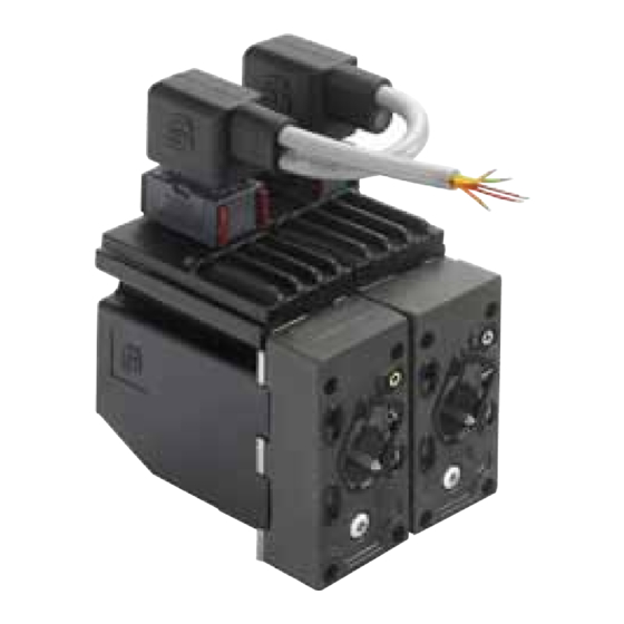
Sauer Danfoss PVED-CX 4 Series Technical Information (96 pages)
Electrohydraulic Actuator
Brand:
Sauer Danfoss
| Category:
Controller
| Size: 2 MB
Table of Contents
Table of Contents
3
Reference
9
Standards
9
Reading Guide
9
Warnings
10
Product Warnings
10
Introduction and
12
Introduction
12
Reading Guide Figure 1: PVG with PVED-CX
12
General Information
13
Overview
13
PVG Functionality
15
PVED-CX Functionality
16
Mechanical Sub System
17
Housing
17
Cable Kit
17
Mounting
17
Mechanical Sub System
18
Hydraulic Subsystem
18
Lvdt
18
Spool Neutral Spring
18
Electrical and Electronic Subsystem
19
Communication
20
Optical - LED
20
Analogue
20
Digital - Canopen
20
Computerized Subsystem
21
Operational Modes
22
Full Operational
22
Hand Operational
22
Automatic System Safety Integrity Self Test - ASSIST
22
Settings
23
Logging
23
Normal Operation
24
Normal Operation- Self and Neighbor Supervision Concept
24
Self and Neighbor
24
Supervision Concept
24
Set Point Command
25
Spool Supervision
25
Solenoid Control
25
Position Reporting
25
Neighbor Supervision
26
Micro-Controller Supervision
26
ASIC Supervision
26
Temperature Supervision
26
Power Save
26
Safety Description
27
Definition
27
POST - Power on Self Test
27
ASSIST - Automatic System Safety Integrity Test
27
Runtime Fault Monitoring
27
Communication Fault
27
Spool Position Fault
28
System Data Fault
28
Electrical Fault
28
Temperature Fault and Correction
28
Test Fault
28
Fault Level
29
Fault Reaction
29
Warning
29
Critical
29
Severe
29
Threshold Not Passed
29
Critical & Severe
29
Fault Reporting
30
Fault Recovery
30
Canbus
30
Error Logs
30
Light Emitting Diode
30
Warning
30
Critical
30
Severe
30
Data Section
31
Operational Conditions
31
Performance
31
Dimensions and Layout
31
Data Section
33
Hydraulic Data
35
Pilot Oil System
35
Pilot Oil Consumption for One PVED-CX
35
Oil Viscosity
35
Filtering
35
Pilot Pressure
35
Oil Temperature
35
Operating Temperature
35
Electrical Data
36
PCB Temperature
36
Version with AMP JPT Connector
36
Communication
37
Led
37
Can
37
Spool Control
38
Spool Positioning
38
Closed Loop
38
Spool Monitoring, Control and Fault Reaction
38
Parameter Settings
39
Node ID
39
EDS Parameters - Constants Read Only
40
EDS Parameters - Variables Read Write
40
Error Register. Variable Read Only
40
Conversion of Identity Parameters to Comparable Values
41
Reading Guide for Product Code and Serial Number
41
Error Log. Variables, Read Only, Voilatile
42
Error List. Variable Read Only
42
Instantaneous Temperature. Variable Read Only
42
Temperature Log
42
Module Control by Canbus
43
Safety Relevant Features
43
Data Section
43
NMT Reset Application
45
NMT Reset Communication
45
Reload Command
46
Changing Node ID Using Layer Setting Service
47
Step-1: Switch to Configuration Mode
48
Step-2: Configure Node ID
49
Step-3: Store New Assigned Node-ID
49
Step-4: Switch to Normal Mode
49
LSS Enquiry Services
50
Enquire Vendor-ID Command
50
Enquire Product Code Command
51
Enquire Revision Number Command
51
Enquire Serial Number Command
51
Enquire Device Node-ID Command
52
Set EDS Parameter
52
Set NNI Example
52
Enquire EDS Parameter
53
Enquire NNI Example
53
Enquire Error Log Example
53
Normal Operation
54
NMT Boot up Object
54
Heartbeat Message
54
Transmission of PVED-CX Spool Pos. Messages on Sync Msg
58
Data Section
59
Assist
60
State Machine
64
Important Points about PVED-CX DSM Implementation
64
INIT State
64
DISABLED State
64
HOLD State
65
DEVICE_MODE_ACTIVE State
65
FAULT_REACTION State
66
FAULT_HOLD State
66
FAULT State
67
State Transition
67
Limitations and Known Software Issues
68
Error Codes
70
Index 1 • Common Name: Reserved
70
Index 2 • Common Name: Supply Voltage too High
70
Index 3 • Supply Voltage too Low
71
Index 4 • Illegal State Command
71
Index 5 • Division by Zero, Illegal SW Operation
72
Index 6 • Internal Table Value Corrupted, Illegal SW Operation
72
Index 7 • Wrong Data Interpretation, Truncation of Values
72
Index 8 • Interpolation Fault, Illegal SW Operation
73
Index 9 • no Handshake to Uc
73
Index 10 • Watchdog Not Starting
73
Index 11 • RTOS Error
74
Index 12 • LVDT Verification Fault
74
Index 13 • Neighbor LVDT Fault
75
Index 14 •Temperature Sensor Fault
75
Index 15 • Fault in RAM
75
Index 16 • Temperature Average to High
76
Index 17 • Code Memory Check Fault
76
Index 18 • Reserved
76
Index 19 • EEPROM Write Fault
77
Index 20 • EEPROM Content Fault
77
Index 21 • EEPROM Mirror Fault
77
Index 22 • Dead Band Parameter out of Range
78
Index 23 • Reserved
78
Index 24 • CAN Error Frame Warning
78
Index 25 • Signal from Master Missing
79
Index 26 • Recovered from Bus off
79
Index 27 • Command Signal Error
79
Index 28 • Reserved
80
Error Codes
80
Index 29 • Reserved
80
Index 30 • Spool Not at Set Point
80
Index 31 • Spool out of Neutral
81
Index 32 • Spool out of Neutral at Boot up
81
Index 33 • Electronics to Warm
82
Index 34 • CAN Spool Position from Neighbor Missing
82
Index 35 • Neighbor CAN Spool Position Fault
83
Index 36 • no Set Point
83
Index 37 • CAN Stack Error
84
Index 38 • DSM Initialization Failed
84
Index 39 • A/D Converting Fault
84
Index 40 • ASSIST. State Fault
85
Index 41 • ASSIST. Timing Fault
85
Index 42 • Neighbor. Spool out of Neutral at Boot up
85
Index 43 • ASSIST. Neighbor Reporting Fault
86
Index 44 • ASSIST. Spool Not Returned to Neutral
86
Index 45 • ASSIST. Step Fault
86
Index 46 • ASSIST. Neighbor Spool Does Not Steer out
87
Index 47 • ASSIST. Neighbor Spool Not Returned to Neutral
87
Index 48 • ASSIST: a Port Gives to High Flow
88
Index 49 • ASSIST: B Port Gives to High Flow
88
Index 50 • ASSIST: a Port Gives to Low Flow
88
Index 51 • ASSIST: B Port Gives to Less Flow
89
Index 52 • Neighbor. Spool out of Neutral
89
Index 53 • Neighbor. Spool Not at Set Point
90
Index 54 • Neighbor. Spool Position Reporting Fault
90
Index 55 • Reference Voltage Fault
91
Index 56 • Node ID Fault
91
Index 57 • EEPROM Address Fault
92
Index 58 • Error Code Buffer
92
Ordering
93
Parameter Agreement Template
93
Parts Manual
95
Part Numbers
95
Advertisement
Advertisement
Related Products
Sauer Danfoss 45 Series
Sauer Danfoss 40 Series
Sauer Danfoss Categories
Water Pump
Engine
Video Game Controller
Control Unit
Touch terminals
More Sauer Danfoss Manuals
Login
Sign In
OR
Sign in with Facebook
Sign in with Google
Upload manual
Upload from disk
Upload from URL