Table of Contents
Advertisement
Quick Links
Advertisement
Table of Contents

Summary of Contents for Sauer Danfoss PVED-CX 4 Series
- Page 1 Electrohydraulic Actuator – PVED-CX Series 4 Technical Information...
- Page 2 Electrohydraulic Actuator – PVED-CX Series 4 Technical Information Revisions Revision History Table of Revisions Date Page Changed Oct 2009 SD layout Jan 2010 Major update Apr 2010 Major update Dec 2010 New back cover Mar 2011 Major update May 2011 2, 54, 68, 96 Minor update May 2011...
-
Page 3: Table Of Contents
Electrohydraulic Actuator – PVED-CX Series 4 Technical Information Table of Contents Reference Reference ................................9 Standards ................................9 Reading Guide ..............................9 Warnings Product Warnings ............................10 Introduction and Introduction ..............................12 Reading Guide Figure 1: PVG with PVED-CX ......................12 General Information Overview .................................13 Figure 2: PVED-CX Functionalities –... - Page 4 Electrohydraulic Actuator – PVED-CX Series 4 Technical Information Table of Contents Normal Operation Normal Operation– Self and Neighbor Supervision Concept ............24 – Self and Neighbor Figure 10: Function cooperation in control section ..............24 Supervision Concept Set Point Command ............................25 Spool Supervision ............................25 Solenoid Control ............................25 Position Reporting ............................25 Neighbor Supervision ..........................26...
- Page 5 Electrohydraulic Actuator – PVED-CX Series 4 Technical Information Table of Contents Data Section Figure 18: Neighbor Guide same as figure 27 ................33 Figure 19: Cable kit specification ....................33 Figure 20: PVED-CX dimensions milimeter [inch] ..............34 Figure 21: PVED-CX on PVG32 dimensions milimeter [inch] ..........34 Hydraulic Data ...............................35 Pilot oil system ............................35 Pilot oil consumption for one PVED-CX ..................35...
- Page 6 Electrohydraulic Actuator – PVED-CX Series 4 Technical Information Table of Contents Data Section NMT Reset Application .........................45 Figure 37: Reset Application Command format ................45 NMT Reset Communication ........................45 Figure 38: Reset Communication Command format ...............45 Reload Command ...........................46 Figure 39: Reload boot up parameters ..................46 Changing Node ID using Layer Setting Service ................47 Step-1: Switch To Configuration Mode ...................48 Figure 40: Switch to Configuration Mode Global Way .............48...
- Page 7 Electrohydraulic Actuator – PVED-CX Series 4 Technical Information Table of Contents Data Section Hand Operational Mode and Full Operational Mode configuration ........59 Figure 65: Transition between Hand operational and Full operational ......59 ASSIST .................................60 Figure 66: ASSIST Pre-trigger command ..................60 Figure 67: ASSIST run command ....................61 Figure 68: Device ASSIST step confirmation ................62 Figure 69: ASSIST successfully completed ...................62...
- Page 8 Electrohydraulic Actuator – PVED-CX Series 4 Technical Information Table of Contents Error Codes Index 29 • Reserved ..........................80 Index 30 • Spool not at set point .......................80 Index 31 • Spool out of neutral ......................81 Index 32 • Spool out of neutral at boot up ..................81 Index 33 •...
-
Page 9: Reference
Electrohydraulic Actuator – PVED-CX Series 4 Technical Information Reference Reference Sauer-Danfoss Doc 520L0344, PVG 32 Technical Information. Standards • International Organization for Standardization ISO 11898-2 Road vehicles, CAN, Part 2, High-speed medium access unit (physical layer) • CAN in Automation: CiA 3.01 v4.02 CANopen protocol. • CAN in Automation: CiA 4.08 v1.51 Device specific protocol for proportional valves. -
Page 10: Warnings
Electrohydraulic Actuator – PVED-CX Series 4 Technical Information Warnings Product Warnings Warning The use of PVED-CX will not guarantee a system to be SIL 2 certified as this is the responsibility of the system integrator. Warning An application with PVG 32 and PVED-CX will only have SIL classification if the whole application has been certified. - Page 11 Electrohydraulic Actuator – PVED-CX Series 4 Technical Information Warnings Product Warnings Warning (continued) Hydraulic oil can cause both environmental damage and personal injuries. Warning Module replacement can introduce contamination and errors to the system. It is important to keep the work area clean and components should be handled with care. Warning After replacement of modules or cables wiring quality must be verified by an ASSIST.
-
Page 12: Introduction And
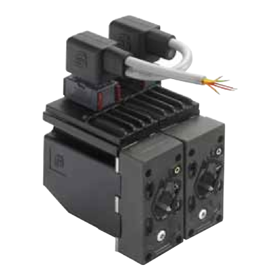
Electrohydraulic Actuator – PVED-CX Series 4 Technical Information Introduction and Reading Guide Introduction The Sauer-Danfoss PVED-CX is a PVE-Series 4 actuator for the PVG32. CX is an abbreviation for CAN bus communication and eXtended safety. The PVED-CX is intended for markets where a documented extended safety is needed. In particular cranes, man-lifts and telehandlers are in focus. -
Page 13: General Information
Electrohydraulic Actuator – PVED-CX Series 4 Technical Information General Information Overview The PVG is a sectioned spool valve stack with up to 12 individually controlled proportional valves. With the PVED-CX the PVG can operate as one or more control sections. A control section is a group of two to eight PVED-CX connected by one cable kit with mutual monitoring and the feature that any PVED can bring the entire control section to safe state if a fault is found. - Page 14 Electrohydraulic Actuator – PVED-CX Series 4 Technical Information General Information Overview (continued) The PVED-CX uses the CANopen protocol, thus following the standard protocol CiA301v402 and the device specific protocol for proportional valves CiA408v151 with a minimum set of vendor specific additions. The physical layer for CAN communication applies to ISO 11898-2 high speed CAN.
-
Page 15: Pvg Functionality
Electrohydraulic Actuator – PVED-CX Series 4 Technical Information PVG Functionality PVG Functionality This chapter will give an overview of the PVG functionality. Figure 4: Valve section with naming P -> A Pilot oil supply B port A port Electronics Neutral spring PVBS NC Solenoid valve <- Retract towards PVE... -
Page 16: Pved-Cx Functionality
Electrohydraulic Actuator – PVED-CX Series 4 Technical Information PVED-CX Functionality PVED-CX Functionality This section has focus on how the PVED-CX works and interacts. Understanding of this must be regarded as a pre-condition for understanding module settings and system operation. The PVED-CX is a mechatronic device , meaning a mechanical, a hydraulic, an electric, an electronic and a computer system interacting with external mechanical, hydraulic, electrical, electronic and computerized systems. -
Page 17: Mechanical Sub System
Electrohydraulic Actuator – PVED-CX Series 4 Technical Information PVED-CX Functionality Mechanical Sub System Housing The housing of the PVED-CX protects the internal parts from the environment and gives by design the optimal interface to cabling, Pilot pressure and spool. Cable kit A special cable kit has been designed for the PVED-CX making it possible to operate in Control Sections of two to eight modules with neighbor monitoring. -
Page 18: Mechanical Sub System
Electrohydraulic Actuator – PVED-CX Series 4 Technical Information PVED-CX Functionality Mechanical Sub System LVDT The Linear Variable Differential Transformer (LVDT) or position sensor is the interface between the mechanical system (spool) and the electronic system. The LVDT must never be mechanically adjusted, bent, damaged or partially blocked as this will lead to incorrect information on spool position. -
Page 19: Electrical And Electronic Subsystem
Electrohydraulic Actuator – PVED-CX Series 4 Vbat3 Technical Information Vbat2 out PVED-CX Functionality Safety Vbat2 in switch Electrical and Electronic The PVED-CX is based on the known PVED-CC series 4 technology with the ASIC core Solenoid valve Subsystem controlling the main functionality of the solenoid valves, and a micro-controller system enable Solenoid valve Analogue... -
Page 20: Communication
Electrohydraulic Actuator – PVED-CX Series 4 Technical Information PVED-CX Functionality Communication The PVED-CX has three methods of communication. • Optical from module • Analogue one way communication • Digital two way communication Optical – LED Blinking and steady light is implemented to facilitate maintenance and application engineering. -
Page 21: Computerized Subsystem
Electrohydraulic Actuator – PVED-CX Series 4 Technical Information PVED-CX Functionality Computerized Subsystem The PVED-CX operates according to defined Device State Machines (DSM) giving conditions for transition between states. The Communication State Machine (CSM) is pre-condition for the DSM. State transitions depends on internal conditions e.g. the sanity of the PVED-CX and can also depend on external conditions e.g. -
Page 22: Operational Modes
Electrohydraulic Actuator – PVED-CX Series 4 Technical Information PVED-CX Functionality Operational Modes The PVED-CX has three accessible operational modes for normal operations. • Full operational. Spool position is controlled and monitored. Device Mode Active. • Hand operational. Spool position is monitored. Device Mode Disabled. • Automatic system safety integrity self test. -
Page 23: Settings
Electrohydraulic Actuator – PVED-CX Series 4 Technical Information PVED-CX Functionality Settings The PVED-CX offers a number of settings for both system information and system operation. The parameters are, as required in CANopen, organized in an Electronic Data Sheet (EDS). The available parameters are both fixed parameters and variable parameters. -
Page 24: Normal Operation
Vbat3 Electrohydraulic Actuator – PVED-CX Series 4 Vbat2 out Safety Technical Information Vbat2 in switch Normal Operation – Self and Neighbor Supervision Concept Solenoid valve enable Solenoid valve Analogue Normal Operation Solenoid The main spool is kept in blocked/neutral position by the neutral spring. By use of the control Controller Valves... -
Page 25: Set Point Command
Electrohydraulic Actuator – PVED-CX Series 4 Technical Information Normal Operation – Self and Neighbor Supervision Concept Set Point Command The Set Point for the PVED is broadcasted on CAN bus by the System Main Controller/ Master. During transmission the signal is evaluated for irregularity by all modules on the bus but only modules programmed for the specific signal will perform further calculations. -
Page 26: Neighbor Supervision
Electrohydraulic Actuator – PVED-CX Series 4 Technical Information Normal Operation – Self and Neighbor Supervision Concept Neighbor Supervision The special PVED-CX cable kit ensures that the supervising module has the spool position from the supervised module as an analogue value and also the reported spool position via CANbus. -
Page 27: Safety Description
Electrohydraulic Actuator – PVED-CX Series 4 Technical Information Safety Description Definition The Sauer-Danfoss definition of safe state transition by fault is: • Spool is placed in blocked position (neutral) The PVED-CX has Active Fault Reaction, e.g. brings the system into a safe state on fault. The PVED-CX safety concept is based on three elements: • POST –... -
Page 28: Spool Position Fault
Electrohydraulic Actuator – PVED-CX Series 4 Technical Information Safety Description Runtime Fault Monitoring Spool position fault (continued) Spool position faults are directly related to the hydraulic performance of the application. These faults indicate difference between demanded and actual spool position. The following categories of position faults are recognized. -
Page 29: Fault Level
Electrohydraulic Actuator – PVED-CX Series 4 Technical Information Safety Description Fault Level The PVED-CX has three fault severity levels. • Warning • Critical • Severe Warning Warning is entered if the fault is expected to have external origin and the PVED performance is certain not to suffer once the state is passed. -
Page 30: Fault Reporting
Electrohydraulic Actuator – PVED-CX Series 4 Technical Information Safety Description Fault Reporting Fault reporting is a part of the communication task and has lower priority than fault reaction. CANbus Appropriate emergency messages are sent out according to the CANopen standard. In case of multiple errors Servere has precedence over Critical that has precedence over Warning. -
Page 31: Data Section
Electrohydraulic Actuator – PVED-CX Series 4 Technical Information Data Section Operational Conditions The PVED-CX will only operate according to this table. Figure 12: Operational conditions Mode Supply Power CAN control Pilot oil pressure Oil main pressure Electronic test. POST Mandatory Optional Optional Optional... - Page 32 Electrohydraulic Actuator – PVED-CX Series 4 Technical Information Data Section Dimensions and Layout Figure 15: Cable dimensions (continued) Long cable 4000 ±50 mm / Short cable 1000 ±50 mm Jn Strip + Wirequard 51418 2 x 1.5 mm + 3 x 0.75 mm Roboslepp Marking Part No.
-
Page 33: Data Section
Electrohydraulic Actuator – PVED-CX Series 4 Technical Information Data Section Dimensions and Layout Figure 17: PVED-CX with cable kit (continued) V310199.B Cable can also be mounted with J1 as the rightmost. Figure 18: Neighbor Guide same as figure 27 Node connector Neighbor connector Jn-1 Example... - Page 34 Electrohydraulic Actuator – PVED-CX Series 4 Technical Information Data Section Dimensions and Layout Figure 20: PVED-CX dimensions milimeter [inch] (continued) 100.3 [3.95] 69.5 [2.74] 25.0 [0.98] 24.5 [0.97] 55.3 [2.18] 106 [4.17] V310033.A Figure 21: PVED-CX on PVG32 dimensions milimeter [inch] 290.5 [11.44] 3.5 [0.14] 109.5 [4.31]...
-
Page 35: Hydraulic Data
Electrohydraulic Actuator – PVED-CX Series 4 Technical Information Data Section Hydraulic Data Pilot oil system Pilot oil consumption for one PVED-CX Filtering in the hydraulic system Oil consumption: Max. allowed 23/19/16 degree of Solenoids depowered 0.2 ÷ 0.4 l/min (ISO 4406, 1999 version) contamination Spool locked by pilot oil 0.1 ÷... -
Page 36: Electrical Data
Electrohydraulic Actuator – PVED-CX Series 4 Technical Information Data Section Electrical Data PCB temperature Version with AMP JPT connector Grade of enclosure* range 0 - 85˚C [32 - 185˚F] IP 66 min. -30˚C [-22˚F] * SW dead-band limit is configurable as EDS temperature max avarage 85˚C [185˚F] parameter. -
Page 37: Communication
Electrohydraulic Actuator – PVED-CX Series 4 Technical Information Data Section Communication Figure 24: LED color interpretation Status Vbat2 Local switch /ASIC Full operational Enabled Enabled Enabled Power save Enabled Enabled Disabled Green Hand operational Enabled Enabled Disabled Warning Enabled Enabled Disabled Orange Fault Critical or Severe... -
Page 38: Spool Control
Electrohydraulic Actuator – PVED-CX Series 4 Technical Information Data Section Spool Control Spool positioning • Extend is defined as spool moving away from PVE and equals positive values. • Retract is defined as spool moving towards PVE and equals negative values. Figure 26: Spool position -7 mm -1.5 mm -1.3 mm -0.7 mm... -
Page 39: Parameter Settings
Electrohydraulic Actuator – PVED-CX Series 4 Technical Information Data Section Parameter Settings Parameter setting in the PVED-CX is done via the Electronic Data Sheet (EDS) as described in the CANopen standard. All parameters are defined by index, sub index and value. An example of he relevant EDS file is available through your Sauer-Danfoss sales representative. -
Page 40: Eds Parameters - Constants Read Only
Electrohydraulic Actuator – PVED-CX Series 4 Technical Information Data Section Parameter Settings EDS Parameters – Constants read only (continued) Figure 30: Fixed parameters in EDS Name Default Index, sub Device type 408: proportional Hydraulic Valve 0x1000, - COB-ID sync Frame type 0: 11-bit ID (CAN 2.0A) 11bit SYNC- 0x1005, - COB-ID: 128 Manufacturer device name... -
Page 41: Conversion Of Identity Parameters To Comparable Values
Electrohydraulic Actuator – PVED-CX Series 4 Technical Information Data Section Parameter Settings Conversion of identity parameters to comparable values (continued) To optimize data storage in the eds-file hexadecimal numbers, ASCII values and reverse writing is used. Reading guide for product code and serial number Product code and serial number is a combination of digits and letters. -
Page 42: Error Log. Variables, Read Only, Voilatile
Electrohydraulic Actuator – PVED-CX Series 4 Technical Information Data Section Parameter Settings Error log. Variables, read only, voilatile (continued) A FIFO fault log, stored in RAM (volatile), of last 50 errors is in the EDS. Position: Index, sub index: from 0x1003, 1 to 0x1003, 32 both included. Error list. -
Page 43: Module Control By Canbus
Electrohydraulic Actuator – PVED-CX Series 4 Technical Information Data Section Module Control by Safety relevant features CANbus Emergency msg. (EMCY) The messages comply with Ref.3 with the extension that byte 3 of the “Manufacture specific Error Field” shows the Occurrence Counter and byte 7 gives the severity level of the relevant error. - Page 44 Electrohydraulic Actuator – PVED-CX Series 4 Technical Information Data Section Module Control by Reset Emergency Message CANbus (continued) The PVED-CX device sends a Reset EMCY message on the CANBus for every fault whenever its get deactivated Figure 35: EMCY reset frame Reset Error message COB-ID Data Length...
-
Page 45: Nmt Reset Application
Electrohydraulic Actuator – PVED-CX Series 4 Technical Information Data Section Module Control by NMT Reset Application CANbus (continued) To reset application, e.g. deactivate all non Severe errors, reset manufacture area of object dictionary and device specific parameters to default value, a Reset Application Command is used. -
Page 46: Reload Command
Electrohydraulic Actuator – PVED-CX Series 4 Technical Information Data Section Module Control by Reload Command CANbus (continued) With this command the master can reload the PVED-CX with boot up values of all or group of parameters in non volatile memory e.g. EEPROM Figure 39: Reload boot up parameters Reload Parameter To EEPROM Identifier Data Length... -
Page 47: Changing Node Id Using Layer Setting Service
Electrohydraulic Actuator – PVED-CX Series 4 Technical Information Data Section Module Control by Important Points for PVED-CX Valve Configuration CANbus (continued) If a valve boots up with a Node ID value outside the valid range e.g. outside {0x10, 0x3F}, then Node ID dependent COB-IDs will be initialized to 0x80000000 e.g. undefined value, and therefore no Set point RxPDO Mapping entry will be mapped to Set point Index at 0x3300 sub 0 and Neighbor-Set point Index at 0x2100 sub 1. -
Page 48: Step-1: Switch To Configuration Mode
Electrohydraulic Actuator – PVED-CX Series 4 Technical Information Data Section Module Control by Step-1: Switch To Configuration Mode CANbus (continued) Switch To Configuration Mode Global Way Only one PVED-CX can be connected to the CAN-BUS and configured at a time. To configure Node ID you must apply to the following sequence of LSS . -
Page 49: Step-2: Configure Node Id
Electrohydraulic Actuator – PVED-CX Series 4 Technical Information Data Section Module Control by Step-2: Configure Node ID CANbus (continued) Figure 42: Configure node Id Node-ID Configuration Identifier Data Length Byte 0 Byte 1 Byte 2 Byte 3 Byte 4 Byte 5 Byte 6 Byte 7 Command... -
Page 50: Lss Enquiry Services
Electrohydraulic Actuator – PVED-CX Series 4 Technical Information Data Section Module Control by LSS Enquiry Services CANbus (continued) Using these services master is able to know device’s LSS address and Node-ID Before performing any of these command/s master device is expected to change the mode of device from normal to configuration e.g. -
Page 51: Enquire Product Code Command
Electrohydraulic Actuator – PVED-CX Series 4 Technical Information Data Section Module Control by Enquire Product Code Command CANbus (continued) This information gives the software product code for the device. Figure 46: Enquire Product Code Enquiry Service: Product Code Identifier Data Length Byte 0 Byte 1 Byte 2... -
Page 52: Enquire Device Node-Id Command
Electrohydraulic Actuator – PVED-CX Series 4 Technical Information Data Section Module Control by Enquire Device Node-ID Command CANbus (continued) Figure 49: Enquire Device Node-ID Enquiry Service: Node-ID Identifier Data Length Byte 0 Byte 1 Byte 2 Byte 3 Byte 4 Byte 5 Byte 6 Byte 7... -
Page 53: Enquire Eds Parameter
Electrohydraulic Actuator – PVED-CX Series 4 Technical Information Data Section Module Control by Enquire EDS parameter CANbus (continued) Figure 52: Set EDS parameter Request ID YY for the node that node NN is monitoring Data Identifier Length Byte 0 Byte 1 Byte 2 Byte 3 Byte 4... -
Page 54: Normal Operation
Electrohydraulic Actuator – PVED-CX Series 4 Technical Information Data Section Module Control by Normal Operation CANbus (continued) The following gives description for operating a configured PVED-CX: NMT boot up object The PVED-CX sends out a message at boot up with the Node ID. Figure 55: NMT boot up - address claim NMT Boot-Up Msg Data... - Page 55 Electrohydraulic Actuator – PVED-CX Series 4 Technical Information Data Section Module Control by Getting to Device Mode Active CANbus (continued) Before it will be possible to send set point commands to the PVED-CX, it is necessary to force each PVED-CX through a state machine into a final state called “Device Mode Active”.
- Page 56 Electrohydraulic Actuator – PVED-CX Series 4 Technical Information Data Section Module Control by PVED-CX node NID CANbus (continued) Figure 58: Setting PVED node NID in device mode active Getting PVED-CX n into “Device Mode Active” Identifier Data Length Byte 1 Byte 2 Byte 3 Byte 4...
- Page 57 Electrohydraulic Actuator – PVED-CX Series 4 Technical Information Data Section Module Control by Set point CANbus (continued) Time guarding on set point RxPDO messages is only active when PVED-CX is in ‘DEVICE_ MODE_ACTIVE’ and in ‘Full operational mode’ . The CANopen set point contains the set point to all valves in a control section. If a Node Id is not present set point should be blocked e.g.
-
Page 58: Transmission Of Pved-Cx Spool Pos. Messages On Sync Msg
Electrohydraulic Actuator – PVED-CX Series 4 Technical Information Data Section Module Control by Transmission of PVED-CX Spool Pos. Messages on Sync Msg CANbus (continued) The PVED-CX sends the filtered spool position on every n’th sync message from the controler. • On which nth SYNC msg device has to send its spool position depends upon its transmission type. -
Page 59: Data Section
Electrohydraulic Actuator – PVED-CX Series 4 Technical Information Data Section Module Control by Hand Operational Mode and Full Operational Mode configuration CANbus (continued) Using object at index 0x6042 and sub-index 0x00 master can change the mode of device from Hand Operational to Full Operational mode or vice versa: Figure 65: Transition between Hand operational and Full operational Device State ¨HOLD¨... -
Page 60: Assist
Electrohydraulic Actuator – PVED-CX Series 4 Technical Information Data Section Module Control by ASSIST CANbus (continued) ASSIST is used for test of the electrical wiring, spool monitoring and spool control. An ASSIST will test every device in a control section individually and automatically. An ASSIST can only be performed on an entire control section To perform ASSIST a group of commands is required to be followed in a given order: 1. - Page 61 Electrohydraulic Actuator – PVED-CX Series 4 Technical Information Data Section Module Control by ASSIST Run Command CANbus (continued) After receiving ASSIST Pre-Trigger and subsequently followed by NMT reset application PVED-CX devices are ready to perform ASSIST and waiting for ASSIST Run command from master.
- Page 62 Electrohydraulic Actuator – PVED-CX Series 4 Technical Information Data Section Module Control by The response messages from device having Node-ID 0x10 while performing ASSIST are CANbus (continued) as follows: Figure 68: Device ASSIST step confirmation ASSIST Step confirmation by PVED-CX Identifier Data Length Byte 0...
- Page 63 Electrohydraulic Actuator – PVED-CX Series 4 Technical Information Data Section Module Control by CANCEL ASSIST Command CANbus (continued) ASSIST can be canceled while the test is performed by control section by using this command. The ASSIST cancelation must be sent to the same node as the ASSIST run command was sent to.
-
Page 64: State Machine
Electrohydraulic Actuator – PVED-CX Series 4 Technical Information Data Section State Machine Important points about PVED-CX DSM Implementation Figure 72: Device State Machine (DSM), same as fig.9 Device state machine Communication state machine Power on Initialisation Reset Application NOT_READY Reset Communication INIT Initialising... -
Page 65: Hold State
Electrohydraulic Actuator – PVED-CX Series 4 Technical Information Data Section State Machine HOLD state: (continued) In this state Master has write access to index 0x6042 (DEVICE_MODE) via SDO messages Master can change DEVICE_MODE of the valve to either ASSIST mode, Hand Operational mode or Full Operational mode. -
Page 66: Fault_Reaction State
Electrohydraulic Actuator – PVED-CX Series 4 Technical Information Data Section State Machine ASSIST Mode • Safety Switch: (continued) Enabled • ASIC solenoid driver circuit: Enabled • Time-Guarding on Neighbor Actual Value RPDO is Enabled • Time-Guarding on Set Point RPDO is Enabled • PVED-CX communicates with control section and master. -
Page 67: Fault State
Electrohydraulic Actuator – PVED-CX Series 4 Technical Information Data Section State Machine FAULT state: (continued) On occurrence of Critical or Severe type of fault in the system, PVED-CX device gets into this state. It sends out appropriate EMCY frame. PVED-CX device needs to be re-booted, in order to take it out from the FAULT state. -
Page 68: Limitations And Known Software Issues
Electrohydraulic Actuator – PVED-CX Series 4 Technical Information Data Section Limitations and Known • The set point range is ±127. Using –128 to +127 is not recommended as this input is Software Issues asymmetric. • It is advisable to perform Save and Reload operations on the valves, when they are in DISABLED state. - Page 69 Electrohydraulic Actuator – PVED-CX Series 4 Technical Information Data Section Limitations and Known • PVED-CX device acts as EMCY consumer and handles EMCY messages sent to it on Software Issues 0x81 message ID. On receiving EMCY Error Code of 0x1000 in the message with (continued) COB-ID of 0x81, PVED-CX device goes to NMT-STOPPED state.
-
Page 70: Error Codes
Electrohydraulic Actuator – PVED-CX Series 4 Technical Information Error Codes Error Codes Index 1 • Common Name: Reserved Obj. Dict. Index 0x2000 CANopen Name Reserved Error code ID 0x8200 Severity Error register 0x11 Error type Filtered Finding Reserved Problem Reserved Likely root cause Reserved Counteraction... -
Page 71: Index 3 • Supply Voltage Too Low
Electrohydraulic Actuator – PVED-CX Series 4 Technical Information Error Codes Error Codes Index 3 • Supply voltage too low (continued) Obj. Dict. Index 0x2002 CANopen Name Power supply voltage to low Error code ID 0x3412 Severity Warning Error register Error type Application Filtered Finding... -
Page 72: Index 5 • Division By Zero, Illegal Sw Operation
Electrohydraulic Actuator – PVED-CX Series 4 Technical Information Error Codes Error Codes Index 5 • Division by zero, illegal SW operation (continued) Obj. Dict. Index 0x2004 CANopen Name Division by zero Error code ID 0x6201 Severity Severe Error register 0x81 Error type Application Filtered... -
Page 73: Index 8 • Interpolation Fault, Illegal Sw Operation
Electrohydraulic Actuator – PVED-CX Series 4 Technical Information Error Codes Error Codes Index 8 • Interpolation fault, illegal SW operation (continued) Obj. Dict. Index 0x2007 CANopen Name Interpolation fault Error code ID 0x6204 Severity Severe Error register 0x81 Error type Application Filtered Finding... -
Page 74: Index 11 • Rtos Error
Electrohydraulic Actuator – PVED-CX Series 4 Technical Information Error Codes Error Codes Index 11 • RTOS error (continued) Obj. Dict. Index 0x200A CANopen Name RTOS Error Error code ID 0x6207 Severity Severe Error register 0x81 Error type Application Filtered Finding The operating system did not perform as expected. -
Page 75: Index 13 • Neighbor Lvdt Fault
Electrohydraulic Actuator – PVED-CX Series 4 Technical Information Error Codes Error Codes Index 13 • Neighbor LVDT fault (continued) Obj. Dict. Index 0x200C CANopen Name Sensor neighbor LVDT Error code ID 0x5232 Severity Critical Error register 0x21 Error type Application Filtered Finding Analogue input from neighbor LVDT is not within specification... -
Page 76: Index 16 • Temperature Average To High
Electrohydraulic Actuator – PVED-CX Series 4 Technical Information Error Codes Error Codes Index 16 • Temperature average to high (continued) Obj. Dict. Index 0x200F CANopen Name Average temperature of PCB is too high Error code ID 0x4223 Severity Warning Error register Error type Application Filtered... -
Page 77: Index 19 • Eeprom Write Fault
Electrohydraulic Actuator – PVED-CX Series 4 Technical Information Error Codes Error Codes Index 19 • EEPROM write fault (continued) Obj. Dict. Index 0x2012 CANopen Name EEPROM verified write to cell Error code ID 0x5532 Severity Critical Error register 0x81 Error type Application Filtered Finding... -
Page 78: Index 22 • Dead Band Parameter Out Of Range
Electrohydraulic Actuator – PVED-CX Series 4 Technical Information Error Codes Error Codes Index 22 • Dead band parameter out of range (continued) Obj. Dict. Index 0x2015 CANopen Name Parameter error dead band compensation Error code ID 0x6321 Severity Critical Error register 0x81 Error type Application... -
Page 79: Index 25 • Signal From Master Missing
Electrohydraulic Actuator – PVED-CX Series 4 Technical Information Error Codes Error Codes Index 25 • Signal from master missing (continued) Obj. Dict. Index 0x2018 CANopen Name Lifeguard heart beat fault, No heartbeat msg monitoring for master and hence Fault code is not used Error code ID 0x8130 Severity... -
Page 80: Index 28 • Reserved
Electrohydraulic Actuator – PVED-CX Series 4 Technical Information Error Codes Error Codes Index 28 • Reserved (continued) Obj. Dict. Index 0x201B CANopen Name ERR_RESERVED_5 Error code ID 0x8303 Severity Reserved Error register 0x81 Error type Reserved Filtered Finding Reserved Problem Reserved Likely root cause Reserved... -
Page 81: Index 31 • Spool Out Of Neutral
Electrohydraulic Actuator – PVED-CX Series 4 Technical Information Error Codes Error Codes Index 31 • Spool out of neutral (continued) Obj. Dict. Index 0x201E CANopen Name CL Monitoring: unintended spool movement Error code ID 0x8306 Severity Critical Error register 0x81 Error type Application Filtered... -
Page 82: Index 33 • Electronics To Warm
Electrohydraulic Actuator – PVED-CX Series 4 Technical Information Error Codes Error Codes Index 33 • Electronics to warm (continued) Obj. Dict. Index 0x2020 CANopen Name Inst temp electronic components too high Error code ID 0x4224 Severity Critical Error register Error type Application Filtered Finding... -
Page 83: Index 35 • Neighbor Can Spool Position Fault
Electrohydraulic Actuator – PVED-CX Series 4 Technical Information Error Codes Error Codes Index 35 • Neighbor CAN spool position fault (continued) Obj. Dict. Index 0x2022 CANopen Name Monitor neighbor data integrity Error code ID 0x8002 Severity Critical Error register 0x91 Error type Communication Filtered... -
Page 84: Index 37 • Can Stack Error
Electrohydraulic Actuator – PVED-CX Series 4 Technical Information Error Codes Error Codes Index 37 • CAN stack error (continued) Obj. Dict. Index 0x2024 CANopen Name CANopen stack error Error code ID 0x8201 Severity Severe Error register 0x11 Error type Communication Filtered Finding Software error in the CANopen protocol stack... -
Page 85: Index 40 • Assist. State Fault
Electrohydraulic Actuator – PVED-CX Series 4 Technical Information Error Codes Error Codes Index 40 • ASSIST. State fault (continued) Obj. Dict. Index 0x2027 CANopen Name ASSIST: operational error Error code ID 0xFF10 Severity Severe Error register 0x81 Error type Application Filtered Finding ASSIST Operational state does not match the expected state. -
Page 86: Index 43 • Assist. Neighbor Reporting Fault
Electrohydraulic Actuator – PVED-CX Series 4 Technical Information Error Codes Error Codes Index 43 • ASSIST. Neighbor reporting fault (continued) Obj. Dict. Index 0x202A CANopen Name ASSIST: diff. between analog and CAN-BUS spoolpos Error code ID 0xFF12 Severity Critical Error register 0x81 Error type Application... -
Page 87: Index 46 • Assist. Neighbor Spool Does Not Steer Out
Electrohydraulic Actuator – PVED-CX Series 4 Technical Information Error Codes Error Codes Index 46 • ASSIST. Neighbor spool does not steer out (continued) Obj. Dict. Index 0x202D CANopen Name ASSIST: neighbor spool does not steer out Error code ID 0xFF15 Severity Critical Error register... -
Page 88: Index 48 • Assist: A Port Gives To High Flow
Electrohydraulic Actuator – PVED-CX Series 4 Technical Information Error Codes Error Codes Index 48 • ASSIST: A port gives to high flow (continued) Obj. Dict. Index 0x202F CANopen Name ASSIST: too much spool movement in A-port Error code ID 0xFF17 Severity Critical Error register... -
Page 89: Index 51 • Assist: B Port Gives To Less Flow
Electrohydraulic Actuator – PVED-CX Series 4 Technical Information Error Codes Error Codes Index 51 • ASSIST: B port gives to less flow (continued) Obj. Dict. Index 0x2032 CANopen Name ASSIST: too less spool movement in B port Error code ID 0xFF1A Severity Critical... -
Page 90: Index 53 • Neighbor. Spool Not At Set Point
Electrohydraulic Actuator – PVED-CX Series 4 Technical Information Error Codes Error Codes Index 53 • Neighbor. Spool not at set point (continued) Obj. Dict. Index 0x2034 CANopen Name CL Monitoring of Neighbor: critical dynamics Error code ID 0x830A Severity Critical Error register 0x81 Error type... -
Page 91: Index 55 • Reference Voltage Fault
Electrohydraulic Actuator – PVED-CX Series 4 Technical Information Error Codes Error Codes Index 55 • Reference voltage fault (continued) Obj. Dict. Index 0x2036 CANopen Name Drift of ADC ref. voltage or SMPS Error code ID 0x3111 Severity Critical Error register Error type Application Filtered... -
Page 92: Index 57 • Eeprom Address Fault
Electrohydraulic Actuator – PVED-CX Series 4 Technical Information Error Codes Error Codes Index 57 • EEPROM address fault (continued) Obj. Dict. Index 0x2038 CANopen Name Invalid EEPROM address Error code ID 0x5535 Severity Severe Error register 0x81 Error type Application Filtered Finding During read or write to EEPROM an address fault was seen. -
Page 93: Ordering
Electrohydraulic Actuator – PVED-CX Series 4 Technical Information Ordering Ordering When PVG32 with PVED-CX are ordered a Settings Agreement must be forwarded as well as assembly specification. Agreements can be made as a • Specific agreement for a single specification • General agreement for PVG The Hydraulic test is a mandatory part of the PVG32 with PVED-CX. - Page 94 Electrohydraulic Actuator – PVED-CX Series 4 Technical Information Ordering Ordering (continued) The list can be extended to twelve modules - relation in control section must be applied. Figure 75: Ctrl sec Node Id and neighbor node Id in group 0x10 0x11 0x12 0x13...
-
Page 95: Parts Manual
Electrohydraulic Actuator – PVED-CX Series 4 Technical Information Accessories / Parts Manual Parts Manual Part numbers Figure 77: Part numbers Sales numbers Name Description 157B4960 PVED-CX PVED-CX for CANopen 11060924 Cable KIT CX, AMP, 2 sections, 4m, w/o termination 11017564 Cable KIT CX, AMP, 3 sections, 4m, w/o termination 11017565... - Page 96 Products we o er: Sauer-Danfoss is a global manufacturer and supplier of high- quality hydraulic and electronic components. We specialize in • Bent Axis Motors providing state-of-the-art technology and solutions that excel in the harsh operating conditions of the mobile o -highway market. •...
Need help?
Do you have a question about the PVED-CX 4 Series and is the answer not in the manual?
Questions and answers