Sign In
Upload
Manuals
Brands
Sartorius Manuals
Transmitter
PR5230
Sartorius PR5230 Manuals
Manuals and User Guides for Sartorius PR5230. We have
1
Sartorius PR5230 manual available for free PDF download: Instrument Manual
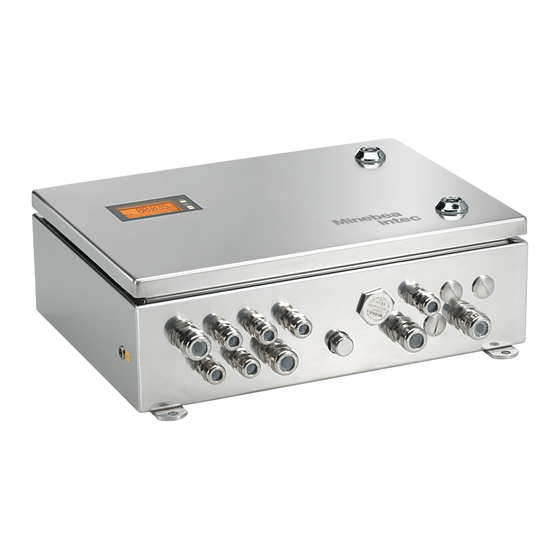
Sartorius PR5230 Instrument Manual (208 pages)
weight transmitter in Field Housing
Brand:
Sartorius
| Category:
Transmitter
| Size: 6 MB
Table of Contents
Table of Contents
3
1 Safety Information
9
Electrical Protective Class
9
Intended Use
9
Initial Inspection
9
Before Commissioning
9
Installation
9
Opening the Instrument
10
Connection of a Protective Earth Conductor to PR5230
10
Power Connection PR5230
10
Failure and Excessive Stress
11
Important Note
11
Maintenance and Repair
11
2 Transmitter in Field Housing
12
Overview of the Instrument
12
Communication Protocols
12
Housing
13
Housing Dimensions
13
Display and Controls
14
Display
14
Status Leds
16
Buttons
17
Operating Via VNC
17
Operation Using Softkeys
20
Selection Using the Navigation Keys (VNC)
20
Tool Tip (VNC)
21
Overview of Connections
22
Plug-In Cards/Junction Board
23
3 Options
24
Option Y2
25
Safety Instructions
25
Description
25
Marking
25
Outputs
25
In Connection with Option W1
25
In Connection with Option WE1
25
Installation
26
Repairs/Cleaning/Maintenance
26
Environmental Conditions
26
Option WE1
27
Safety Instructions
27
Description
27
Marking
27
Display
27
In Connection with Option Y2
27
Weighing Electronic Board for Zone 1 and 21
28
Connection Within the Ex Area
29
Installation
30
Repairs/Cleaning/Maintenance
34
Technical Data
35
4 Installing the Instrument and Plug-In Cards
37
Mechanical Preparation
37
Hardware Construction
37
Main Board
38
Display Board
39
Weighing Electronic Board
39
Cable Gland and Connection
40
Network Port
42
Optocoupler Inputs
42
Opto-Decoupled Outputs (Optional)
44
Relay Outputs
45
Interface RS-485
46
Interface RS-232
54
Accessories
56
Installing Plug-In Cards
56
PR5230/06 Analog Output Board
57
PR5230/22 Load Cell Junction Board
58
PR1721/41 Profibus-DP Interface
59
PR1721/42 Interbus-S Interface
61
PR1721/44 Devicenet Interface
63
PR1721/45 CC-Link Interface
66
PR1721/46 Profinet I/O Interface
68
PR1721/47 Ethernet-IP Interface
70
PR5230/30 Ethernet Socket
72
PR5230/31 Ethernet Cable
72
Connecting Load Cells
73
Connecting a Load Cell with 4-Wire Cable
73
Connecting PR6221 Load Cells
73
Connecting up 2 to 4 Load Cells Via PR5230/22 Load Cell Junction Board
74
Connecting up 2 to 8 Load Cells Using 6-Wire Connecting Cable
78
Connecting Load Cells with External Supply
79
Connecting Platforms (CAP
80
5 Commissioning
81
Data Protection/Power Failure
81
CAL Switch
81
Switching on the Instrument
82
Resetting the Instrument/Activating Network 'DHCP
82
Searching the Instrument in the Network with 'Indicator Browser
85
Operation Using a PC
88
Operation Using the VNC Program
88
System Messages During Input (VNC)
89
Operation Using Web Browser
90
Function INFO
92
Setup Function (VNC)
92
Setup Menu (VNC)
93
Calibration Menu
94
Calibration
95
Displaying Calibration Data
95
Selecting the Calibration Mode
96
Determining the Maximum Capacity [Max]
97
Determining the Scale Interval
99
Determining the Dead Load
100
Calibration with Weight [By Load]
102
Calibration with MV/V Value [By MV/V]
103
Calibration with Load Cell Data (Smart Calibration)
104
Subsequent Dead Load Correction
105
Determination Test Value/Display Test Value
105
Finishing/Saving the Calibration
106
Parameter Input
107
Error Messages
110
Measuring Circuit Error Messages
110
General Error Messages
110
Error Messages with Ex Applications
111
Configuring General Parameters
112
Serial Interfaces [Serial Ports]
112
Date and Time
115
Operating Parameters
116
Printing Parameter
117
Fieldbus Parameter
118
Network Parameter
120
Display Items
121
Limit Values, Digital Inputs and Outputs
122
Conditions for Limit Values and Digital Inputs, States for Outputs
122
Configuring Digital Inputs and Outputs
123
Configuring Limit Values
126
Display of Limits and Digital Inputs/Outputs
128
Analog Output
129
Adapting the Analog Output
130
Retrieve Eventlog Memory
131
Fatalerror
131
Setup
132
Indicator
132
Powerfail
132
5.10 Backup of EAROM
132
5.11 Configureit Professional
133
Installation
133
Program Start
135
Establish Communication to the Instrument
137
Transfer Dataset from Instrument to PC
138
Store Current Dataset on PC
139
Store Current Dataset or Selected Parameters in the Instrument
141
Reset the Instrument to Factory Default
142
Exporting a Dataset as Printable File
142
Operation of the Instrument Via Browser (VNC)
143
5.11.10 Closing the Program
143
6 Bus/Modbus Protocol
144
General Description
144
Modbus-RTU
145
Modbus-TCP/-UDP
146
Functions
147
Function 1 or 2: Reading N Bits
147
Function 3 or 4: Reading N Successive Words
147
Function 5: Writing a Bit
148
Function 6: Writing a Word
148
Function 8: Diagnosis
149
Function 15: Writing N Successive Bits
149
Function 16: Writing N Successive Words
150
Error Messages
150
Word Addresses
151
7 SMA Protocol
152
General
152
Description of Used Symbols
152
SMA Command Set
153
Requesting a Weight
153
Controlling the Scale
155
Scale Diagnosis
155
Scale Data
156
Scale Information
156
Escape Command
156
SMA Reply Messages
156
Standard Reply
156
Reply with Unknown Command
158
Reply in Case of Communication Error
158
Reply with Diagnosis Command
158
Reply with 'A' and 'B' Command
159
Scale Reply with 'I' and 'N' Commands
160
Communication Error
161
8 Asycom Protocol
162
Commands of the Weight Function
162
Other Commands
163
SPM Commands
163
Error Messages for Asycom Commands
164
9 Fieldbus Interface
165
Fieldbus Interface Protocol
165
Write Window (Input Area)
166
Read Window (Output Area)
166
Reading and Writing Data
166
Description of the I/O Area (Read / Write Window)
167
Input Area
167
Output Area
168
Reading and Writing Register Via Fieldbus
169
Example: Reading the Gross Weight
171
Fieldbus Register
172
Register 0: IO Status Bits for Reading
172
Register 1: Scale Status
172
Register 2: State of State-Controlled Action Bits
173
Register 4: Calibration Information, Error Byte
173
Register 5: Device Type and Software Release
174
Register 6: Board Number
174
Register 7: (Reserved)
174
Register 8
174
Register 24
175
Register 30, 31: Fixed Values (Read/Write)
175
Register 80
175
10 Global SPM Variables
176
11 Configuration Print-Out
178
12 Repairs and Maintenance
180
12.1 Battery for Date/Time
180
Battery Replacement
180
12.2 Solder Work
181
12.3 Cleaning
181
13 Disposal
181
14 Specifications
182
Instructions for Use of 'Free Software
182
14.2 Decoding of the Serial Number
182
14.3 General Data
182
Backup Battery for Time/Date
182
Power Connection 230 V AC
182
Power Connection 24 V DC
182
14.4 Effect of Ambient Conditions
183
Environmental Conditions
183
Electromagnetic Compatibility (EMC)
183
RF Interference Suppression
183
14.5 Weighing Electronics
184
Load Cells
184
Connecting Cable
184
Principle
184
Accuracy and Stability
184
Sensitivity
184
Analog Output (Option PR5230/06)
185
Digital Inputs
185
Digital Outputs
185
Serial Interfaces
185
14.5.10 Network Interface
186
Fieldbus Interfaces (Options)
186
14.6 Mechanical Data
186
Construction
186
Dimensions/Weights
186
Use in Legal-For-Trade Mode
186
Documentation for Verification on the Enclosed CD
186
Additional Instructions
186
15 Index
187
16 Appendix
191
Advertisement
Advertisement
Related Products
Sartorius PR 5211 Series
Sartorius PR 5211/00
Sartorius PR 5211/11
Sartorius PR 5211/10
Sartorius PR 5220 Series
Sartorius PR 5220/00
Sartorius PR 5220/01
Sartorius PR 5220/04
Sartorius PR 5220/06
Sartorius PR 5220/07
Sartorius Categories
Scales
Laboratory Equipment
Measuring Instruments
Water Filtration Systems
Accessories
More Sartorius Manuals
Login
Sign In
OR
Sign in with Facebook
Sign in with Google
Upload manual
Upload from disk
Upload from URL