Sign In
Upload
Manuals
Brands
Sanyo Denki Manuals
Controller
SANMOTION 3E S
Sanyo Denki SANMOTION 3E S Manuals
Manuals and User Guides for Sanyo Denki SANMOTION 3E S. We have
1
Sanyo Denki SANMOTION 3E S manual available for free PDF download: Instruction Manual
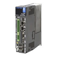
Sanyo Denki SANMOTION 3E S Instruction Manual (488 pages)
EtherCAT Interface For Rotary Motor, Linear Motor
Brand:
Sanyo Denki
| Category:
Controller
| Size: 7 MB
Table of Contents
Table of Contents
14
1 Preface
23
Introduction
24
Product Overview
24
Features of "SANMOTION R" 3E Model
25
Cautions for Replacement from "SANMOTION R" ADVANCED MODEL
26
Instruction Manual
27
Precautions Related to These Instructions
28
Illustration of System Components
29
Model Number Structure
38
Servo Motor Model Number
38
Linear Motor Model Number (DS, DD Series)
40
Linear Motor Model Number (DS/DD Series, Small Type)
41
Linear Motor Model Number (DT Series)
42
Power Unit Model Number
43
Power Unit Model Number
46
Servo Amplifier Model Number
46
Part Names
47
Servo Amplifier
47
Power Unit
56
Amplifier Unit
57
Servo Motor
59
Linear Motor
66
2 Specifications
67
Cooling Fan Specifications
68
Exterior Dimensions/ Specifications/ Mass
68
General Specifications
68
Servo Motor
68
Mechanical Specifications/ Mechanical Strength/ Working Accuracy
69
Oil Seal Type
70
Holding Brake
72
Degree of Decrease Rating for R1□A / R2□A Motor, with Oil Seal and Brake
75
Exterior Dimensions/ Specifications/ Mass
76
General Specifications
76
Linear Motor
76
Mechanical Specifications
76
Moving Direction of Linear Motor (DD/DS/DT Series)
77
Absolute Encoder
79
Motor Encoder
79
Battery Specification
80
Incremental Encoder Specifications
80
Applicable Linear Encoder
81
Linear Encoder
81
Servo Amplifier
82
General Input/Output
85
Inrush Current, Leakage Current
89
Power Supply Calorific Value
89
Calorific Value
91
Operation Pattern
95
Time of Acceleration and Deceleration, Permitted Repetition, Loading Precaution
95
Specifications for Analog Monitor
98
Monitor for Velocity, Torque, and Position Deviation
99
Allowable Frequency, Instantaneous Tolerance, Decreasing the Rotation Angle of the Dynamic Brake
100
Specifications for Dynamic Brake
100
Allowable Regenerative Power
106
Minimum Values of Built-In/ External Regenerative Resistor
106
Regeneration Process
106
3 Installation
107
Precautions
108
Servo Amplifier
108
Unpacking
109
Mounting Direction and Location
110
Arrangement Within the Cabinet
111
Installation
112
Precautions
112
Rotary Motor
112
Unpacking
112
Mounting Method
113
Waterproofing and Dust Proofing
113
Gear Installation and Integration with the Target Machinery
114
Protective Cover Installation
114
Allowable Bearing Load
116
Cable Installation Considerations
119
Linear Motor
120
Precautions on Linear Motor Installation
120
Unpacking
123
Installation of Flat-Type Linear Motor with Core
124
Installation of Twin-Type Linear Motor with Core
128
Installation of Center Magnet Type Linear Motor with Core
133
Installation of Cylinder-Type Motor
136
4 Wiring
137
Part Name and Function
138
Wiring for the Terminal of High Voltage and Grounding
138
Wire
141
Wire Size - Allowable Current
141
Recommended Wire Size (Rotary Motor)
142
Recommended Wire Size (Linear Motor)
146
Wiring for Servo Motor
148
Example of Wiring
152
Crimping of Wires
159
High Voltage Circuit Terminal; Tightening Torque
160
IN, out Connectors Pin Assignment
163
Wiring with Host Unit
163
CN4 Connector Pin Assignment
165
CN2 General I/O Connector Pin Assignment
166
Wiring of Motor Encoder
169
EN1, EN2 Pin Assignment
170
Connector Model Number for Motor Encoder
171
Encoder Cable Length
173
Recommended Encoder Cable Specification
173
Connector Model Number for Thermostat of Servo Motor FAN
174
Wiring for Thermostat of Servo Motor FAN (for 400 VAC)
174
Wiring for Thermostat of Servo Motor FAN (for 400V AC)
174
External Alarm Input, Dynamic Brake Signal and Thermostat
175
Pin Assignment of External Alarm Input (CN8) (RS3W60#)
175
Wiring of External Alarm Input (CN8) (RS3W60#)
175
Terminal Block Pin Assignment for Dynamic Brake Signal/Thermostat (400 VAC)
176
Wiring of Dynamic Brake Signal/Thermostat (RS3C30#)
176
Wiring of Dynamic Brake Signal/Thermostat (RS3D80#)
177
Peripheral Equipments
178
Power Supply Capacity and Peripherals List (Rotary Motor)
178
Peripheral Equipments
179
Power Supply Capacity and Peripherals List (Linear Motor)
181
5 Linear Motor
183
Illustration of System Components
184
Linear Motor
184
EN1, EN2 Signal Names and Pin Numbers
185
Wiring of Linear Encoder
185
EN1, EN2 Pin Assignment
187
Encoder Cable Length
188
Recommended Encoder Cable Specification
188
Linear Motor Control-Related Parameters
189
Setting of System Parameters
189
Setting of Linear Encoder
190
Setting of Magnetic Pole Position Parameters
191
Setting of Moving Direction
193
Check of Installation and Wiring
194
Test Operation
194
Preparation before Operation
195
Magnetic Pole Position Estimation
196
Check of Operation
197
Precautions
198
Setting of Parameters to Combine Amplifier and Motor
198
When You Use SANYO DENKI Servo Amplifier with Other Manufacturer Linear Motor Combined
198
Automatic Magnetic Pole Position Estimation Function
199
6 Servo Tuning
201
Servo Tuning Functions
202
Servo Tuning Functions and Basic Adjustment Procedure
202
Tuning Method Selection Procedure
204
Adaptive Notch Filter Function
205
Auto-Tuning Function
207
Automatically Adjusted Parameters in Auto-Tuning
211
Adjustable Main Parameters During Auto-Tuning
213
Unavailable Functions During Auto-Tuning
214
Auto-Tuning Characteristic Selection
215
Adjustment Method for Auto-Tuning
216
Monitoring Servo Gain Adjustment Parameters
216
Manual Tuning Method Using Auto-Tuning Results
217
Manual Tuning Function
218
Servo System Configuration and Servo Adjustment Parameters
218
Basic Manual Tuning Method for Position Control
220
Basic Manual Tuning Method for Velocity Control
220
The Function of Making Servo Gain Higher
221
Velocity Loop Phase Lead Compensation
221
Position Loop Phase Lead Compensation
222
Torque Feed Forward Compensation
223
Model Following Control Function
224
Manual Tuning Method for Model Following Control
225
Switching of the Feedback Control and the Model-Following (Vibration Suppression) Control
226
Model Velocity Feed Forward Differential Compensation
227
Auto Notch Filter Tuning Function
228
Model Following Vibration Suppression Control
230
Vibration Suppression Function
230
Auto FF Vibration Suppression Frequency Tuning
233
FF Vibration Suppression Control
234
CP Vibration Suppression Control
236
Minor Vibration Suppression
237
Disturbance Impact Suppression Function
238
High Order Integral Control
238
Disturbance Observer Function
239
Stick-Slip Behavior Compensation Function
240
7 Digital Operator
241
Ethercat Indicator
242
IN/OUT Link / Activity Indicator Code: in L/A, out L/A
242
RUN Indicator Code: RUN
242
RUN Indicator Code: RUN
243
Error Indicator Code: ERR
244
Control Power Supply Establish Indicator Code: POW
245
Main Circuit Power Supply Indicator Code: CHARGE
245
Servo Amplifier Indicator
245
Digital Operator Indicator
246
Digital Operator Names and Functions
246
Mode Changes
246
Digital Operator Display Form
247
Forward/Inverse Limit State Display
250
Servo Amplifier Status Display
250
Status Display Mode
250
Display of Linear Motor Magnetic Pole Position Detection Process
251
Display of Warning State
251
Alarm Display
252
How to Reset Alarm When Alarm Occurring
252
Trial Run Mode
253
Velocity-Controlled JOG Operation
253
Automatic Tuning Result Writing
254
Encoder Clear
254
Holding Brake Control (Disabled)
255
Alarm History Display Mode
256
Alarm History Mode
256
Clear Alarm History
256
Monitor Display Mode
257
Monitor List
258
Monitor Details
259
Analog Monitor
269
Fixed Monitor Display
269
9 Dedicated Function
337
Full-Closed System
338
Illustration of System Components
338
Internal Block Diagram
339
Combination Encoder
340
Signal Names and Its Pin Numbers for External Encoder (EN2)
341
Wiring
341
Basic Setting of Full-Closed System
343
Specification Confirmation
343
System Parameter Setting
344
Full-Closed Encoder Selection
345
Feedback Pulse Setting
346
Rotation Direction Setting for Servo Motor
349
Dual Position Feedback Compensation Setting
350
Alarm Detection Setting
351
External Encoder Signal Output Waiting Function Setting
352
External Encoder Operation
353
Power Supply for External Encoder
353
Precautions
353
Illustration of System Components
354
Tandem Operation
354
Wiring
357
How to Use
359
Error Detection
360
Torque Assisting Function
361
Velocity Assisting Function
363
Precaution
364
10 Safe-Torque-Off (Sto) Function
365
Illustration of System Configuration
366
Safe-Torque-Off Function
366
Outline
367
Residual Risk
368
Risk Assessment
368
Standards Conformity
368
Delay Circuit
369
Wiring
370
Example of Wiring
371
Safety Input-Off Shot Pulse for Safety Device Self-Diagnosis
373
Safe-Torque-Off Operation
374
Safe-Torque-Off State
374
Restoration from Safe-Torque-Off State
375
Safe-Torque-Off During Servo Motor Running
376
Safe-Torque-Off During Servo Motor Stoppage
378
Deviation Clear
379
Safety Input Signal Failure Detection
379
Connection Example
380
Error Detection Monitor (EDM)
380
Specifications
380
Error Detection Method
381
Acceptance Criteria
382
Confirmation Procedure
382
Preparation
382
Verification Test
382
Safety Precautions
383
11 Selection
385
Flowchart of Servo Motor Sizing
386
Servo Motor Sizing
386
Calculate Motor Shaft Conversion Load Moment of Inertia (J )
387
Make an Operation Pattern
387
Calculate Motor Shaft Conversion Load Torque (T )
388
Calculate Acceleration Torque (T )
390
Calculate Deceleration Torque (T )
390
Calculate Effective Torque (Trms)
390
Judgment Condition
390
Flowchart of Linear Motor Sizing
391
Linear Motor Sizing
391
Maximum Necessary Force and Necessary Effective Force
392
Select Magnet Rail
393
Cautions on Load Conditions
394
How to Find "Regeneration Effective Power (PM)" of the Horizontal Axis Drive by a Formula
395
Selection of Regenerative Resistor
395
How to Find "Regeneration Effective Power (PM)" of the Vertical Axis Drive by a Formula
396
Selection of Regenerative Resistor
397
Selection of External Regenerative Resistor
399
Specification of External Regenerative Resistor
401
Connection of Regenerative Resistor
402
Protection Function of Regenerative Resistor
405
Thermostat Connection of External Regenerative Resistor
405
Confirmation Method of Regeneration Power PM in Actual Operation
406
Precautions for External Regenerative Resistor Use
407
12 Appendix
409
Standards Conformity
411
Connection and Installation
412
Over-Voltage Category,Protection Grade,Pollution Level
412
UL File Number
412
EMC Installation Requirements
414
Precautions for Noise Filter Connection
418
Servo Motor Dimensions
419
Servo Motor Data Sheet
420
Rs3A05A□Hl
422
Rs3□03A□Hl
422
Rs3A07A□Hl
423
Rs3A10A□Ha
423
Rs3A15A□Ha
424
Rs3A30A□Hl
424
Amplifier Unit :RS3W60
425
Power Unit :RS3PAA270
425
Unit Installation Drawing (600 A)
426
Rs3C02A□Ha
428
Rs3C05A□Ha
428
Rs3C10A□Ha
429
Rs3C15A□Hl
429
Rs3C30A□Hm
430
Power Unit Dimensions
431
Amplifier Unit Dimensions
432
Rs3D80A□□M
432
Optional Parts
441
Analog Monitor Related Item
450
Battery Backup Absolute Encoder (Encoder Code: P) Related Items
450
Junction Cable for Servo Motor
451
Servo Motor Power Cable
453
Power Cable for Servo Motor FAN
463
External Regenerative Resistor
464
Thermostat Cable for Servo Motor FAN
464
Servo Motor FAN Power Cable
465
Connection Cable between Units
466
External Regenerative Resistor
466
Copper Bus Bar
467
Optional Parts Dimensions
471
Dedicated Cable Outline Drawing
473
Monitor Box Outline Drawing
473
Outline Drawing of USB Communication Cable
474
Servo Motor Power Cable Outline Drawing
475
Servo Motor Encoder Cable Dimensions
479
Power Cable Dimensions for Servo Motor FAN
480
Servo Motor Brake Cable Dimensions
481
Thermostat Cable Dimensions for Servo Motor FAN
481
Outline Drawing of Regenerative Resistor
482
Copper Bus Bar
485
Advertisement
Advertisement
Related Products
Sanyo Denki Sanmotion R
Sanyo Denki Sanmotion R 3E S
Sanyo Denki SANMOTION K
Sanyo Denki SANMOTION KB402
Sanyo Denki SANMOTION KB404
Sanyo Denki SANMOTION KB406
Sanyo Denki SANMOTION KA506
Sanyo Denki SANMOTION KA511
Sanyo Denki SANMOTION KA720
Sanyo Denki SANMOTION KA730
Sanyo Denki Categories
UPS
Servo Drives
Controller
Computer Hardware
Stepper Machine
More Sanyo Denki Manuals
Login
Sign In
OR
Sign in with Facebook
Sign in with Google
Upload manual
Upload from disk
Upload from URL