Sign In
Upload
Manuals
Brands
Samsung Manuals
PBX
OfficeServ 7070
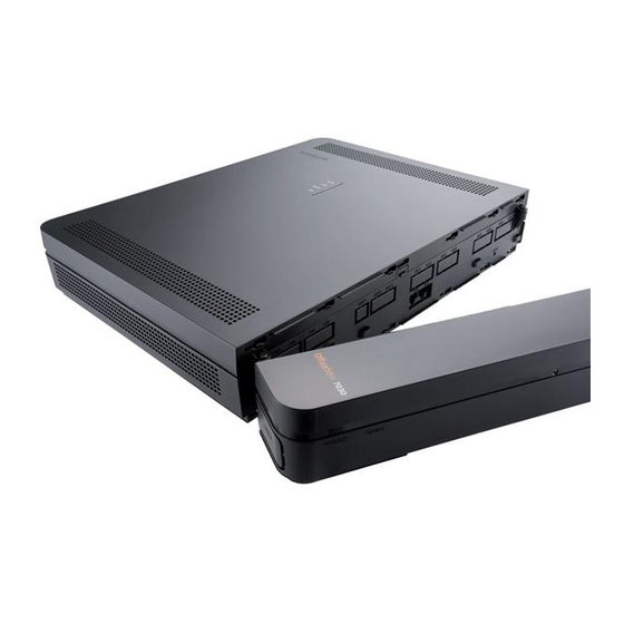
Samsung OfficeServ 7070 Manuals
Manuals and User Guides for Samsung OfficeServ 7070. We have
2
Samsung OfficeServ 7070 manuals available for free PDF download: System Description, Installation Manual
Samsung OfficeServ 7070 System Description (95 pages)
PBX/PABX Phone System
Brand:
Samsung
| Category:
PBX
| Size: 2 MB
Table of Contents
Introduction
3
Document Content and Organization
3
Conventions
4
Reference
4
Revision History
4
Table of Contents
5
CHAPTER 1. Overview of Officeserv 7070
11
Introduction to System
11
Main Functions
11
System Architecture
13
Figure 1.1 Configuration of Officeserv 7070 Service
13
Interfaces between Voip Components
15
Programming
15
CHAPTER 2. Hardware of Officeserv 7070
17
Features of Hardware
17
Cabinet Configuration
19
Cabinet View
19
Figure 2.1 Officeserv 7070 Top View
19
Table 2.1 Parts on the Top of Officeserv 7070
19
Figure 2.2 Officeserv 7070 Side View-1
20
Figure 2.3 Officeserv 7070 Side View -2
20
Table 2.2 Parts on the Side of Officeserv 7070-1
20
Table 2.3 Parts on the Side of Officeserv 7070-2
20
Slot Configuration
21
Table 2.4 Mountable Boards for Different Slots
21
Boards by Functions
22
Control Board
22
Table 2.5 Boards by Functions
22
Table 2.6 BMP Specification
23
Figure 2.4 BMP (MAIN Part)
24
Table 2.7 BMP (MAIN Part) Configuration
24
Figure 2.5 BMP (B8S Part)
27
Table 2.8 BMP (B8S Part) Configuration
27
Figure 2.6 BMP (B8S Part) Line Connection Part
28
Table 2.9 BMP (B8S Part) Ports for External Connections
28
Voice Trunk Board
29
Figure 2.7 PRM Board
30
Table 2.10 PRM Board Configuration
30
Figure 2.8 4TRM Board
32
Figure 2.9 2BRM Board Appearance
33
Voice Station Board
34
Figure 2.10 4SL2 Board
34
Table 2.11 4SL2 Board Configuration
34
Figure 2.11 4DLM Board
35
Table 2.12 4DLM Board Configuration
35
Figure 2.12 E8S Board
37
Table 2.13 E8S Board Configuration
37
Figure 2.13 E8S Line Connection Part
38
Table 2.14 E8S Ports for External Connections
38
Station Phones
39
Regular Phones
39
Digital Phones
39
Figure 2.14 Regular Phone
39
Figure 2.15 DS-24SE
39
Figure 2.16 DS-2024E
40
Figure 2.17 DS-3020S
40
Figure 2.18 DS-4028D
41
Figure 2.19 DS-5012L
41
Figure 2.20 DS-5014D
42
Figure 2.22 DS-5038D
42
IP Phones
43
Figure 2.23 ITP-5112L
43
Figure 2.24 ITP-5114D
43
Add on Module
44
Figure 2.26 DS-5064B
44
Table 2.15 AOM Type
44
Door Phone Interface Module
45
Figure 2.27 DPIM
45
Wireless LAN Device
46
Wireless LAN Base Station (DUAL Band AP)
46
Mobile Phone
46
Figure 2.28 SMT-R2000
46
Figure 2.29 SMT-W5100
46
Additional Devices
47
On Hold/Background Sound Source
47
External Broadcasting Units
47
Loud Bell
47
Common Bell
47
WEB Management
48
Smdr
48
Cti
48
CHAPTER 3. Specification of Officeserv 7070
49
System Capacity
49
Table 3.1 Officeserv 7070 Line Capacity
49
Trunk Line Capacity
50
Station (Subscriber) Line Capacity
50
Table 3.2 Officeserv 7070 System Capacity
50
Table 3.3 Trunk Line Capacity
50
Table 3.4 Station Line Capacity
50
Channel Capacity
51
Table 3.5 Channel Capacity of Slot
51
Electrical Specification
52
Signal Specification
52
Figure 3.1 Trunk Line Loop Start Signaling
52
Table 3.6 Electrical Characteristics of the PRI Trunk Line
52
Table 3.7 Electrical Characteristics of the DLI Line
53
Table 3.8 Electrical Characteristics of the LAN Interface (100 BASE-TX)
53
Transmission Characteristics
54
Line Conditions
54
Power Specification
55
Officeserv 7070 System Power
55
Table 3.9 I/O Voltage of PSU
55
Rings and Tones
56
Ring Cycles
56
Tones
56
Table 3.10 System Ring Cycles
56
Table 3.11 Cycles of the System Tones
56
Available Terminals
57
Table 3.12 Officeserv 7070 Compatible Terminals
57
CHAPTER 4. Functions of Officeserv 7070
59
Call Functions
59
Dynamic IP Address Configuration
59
VMS Function
59
Voip Function
60
Voip Network
60
Voip Trunk Interface
60
Proxy Server
60
Registering Users
60
SIP Phone Configuration
60
Registering SIP Phones
61
Call Log
61
Call Pickup
61
Unconditional Call Forwarding
61
Busy Call Forwarding
61
No Answer Call Forwarding
61
Conference
61
Call Park (System Hold)
61
Do Not Disturb (DND)
62
Call Reservation
62
VMS Function
62
System Features
62
Auto Attendant
64
Access Manager
66
Voice Mail Features
69
Administration Features
78
Voice Form Questionnaire Features
79
E-Mail Gate Way Function
80
Simple Auto Relay Function
80
Web Management
81
Web Management Function
81
ANNEX A. Open Software Announcement
83
Advertisement
Samsung OfficeServ 7070 Installation Manual (79 pages)
Brand:
Samsung
| Category:
Network Hardware
| Size: 3 MB
Table of Contents
Introduction
5
Document Content and Organization
5
Conventions
6
Reference
7
Revision History
7
Safety Concerns
9
Symbols
9
Warning
10
Table of Contents
13
CHAPTER 1. Before Installing
19
Site Information
19
Grounding Conditions
20
Power Conditions
20
Table 1.1 I/O Voltage of PSU
20
Checking the Package
21
Table 1.2 Package Items
21
Cabinet Configuration
22
Figure 1.1 Officeserv 7070 Top View
22
Table 1.3 Parts on the Top of Officeserv 7070
22
Figure 1.2 Officeserv 7070 Side View -1
23
Figure 1.3 Officeserv 7070 Side View -2
23
Table 1.4 Parts on the Side of Officeserv 7070-1
23
Table 1.5 Parts on the Side of Officeserv 7070-2
23
System Installation Procedure
24
CHAPTER 2. Mounting and Replacing the Boards
25
Opening the Cabinet
25
Figure 2.1 Removing the Cable Duct Cover (1)
25
Figure 2.2 Removing the Cable Duct Cover (2)
26
Figure 2.3 Removing the Screws
26
Figure 2.4 Removing the Top Cover
26
Mounting the Boards
27
Table 2.1 Installable Boards for Different Slots
27
Table 2.2 Line Capacity
27
BMP Board
28
Figure 2.5 Setting the BMP (MAIN Part) Board Switches
28
Table 2.3 the BMP (MAIN Part) Board Switches
29
Table 2.4 Installation Locations for the Option Boards of the BMP (MAIN Part)
30
Figure 2.7 Installing Option Boards on the BMP (B8S Part)
31
Table 2.5 Installation Locations for the Option Boards of the BMP (B8S Part)
31
E8S Board
32
Figure 2.8 Removing the Cabinet Dummy
32
Figure 2.9 E8S Fixing the Supports for the E8S
33
Figure 2.10 Installing the E8S Board
33
Figure 2.11 Fixing the E8S Board
34
Figure 2.12 Installing Option Boards on the E8S
35
Table 2.6 Installation Locations for the Option Boards on the E8S Board
35
Option Boards
36
Figure 2.13 Installing the PRM Board
36
Figure 2.14 Installing the 4TRM Board
37
Figure 2.15 Installing the 2BRM Board
37
Figure 2.16 Installing the 4DLM Board
38
Figure 2.17 Installing the 4SL2 Board
38
Closing the Cabinet
39
Figure 2.18 Installing the Top Cover
39
Figure 2.19 Tightening Screws
39
Figure 2.20 Removing the Cable Guide of the Officeserv 7070
40
Figure 2.21 Installing the Duct Cover (1)
40
Figure 2.22 Installing the Duct Cover (2)
40
Replacing the Boards
41
Figure 2.23 Turning off the Cabinet Power
41
Figure 2.24 Removing the Boards
41
Figure 2.25 Replacing the Daughter Boards
42
Figure 2.26 Removing E8S
42
CHAPTER 3. Installing the System
43
Installing on a Wall
43
Precautions to Take When Installing the Officeserv 7070
43
Required Tools
44
Installation
44
Figure 3.1 Required Tools for the Installation on a Wall
44
Figure 3.2 Installation on a Wall (1)
44
Figure 3.3 Installation on a Wall (2)
44
Figure 3.4 Installation on a Wall (3)
45
Figure 3.5 Installation on a Wall (4)
45
Connecting the Ground Cable
46
Figure 3.6 Connecting the Ground Cable
46
CHAPTER 4. Connecting the External Batteries
47
Connecting External Batteries
47
Figure 4.1 Connecting External Battery Cable to Internal Connector of PSU
48
Figure 4.2 Connecting External Battery Cable
48
Caution When Connecting the Power
49
Connecting the Power
49
Figure 5.1 Connecting the Power
50
Connecting a Shunting Telephone Line for Power Failure Protection
51
Figure 5.2 Connecting a Shunting Telephone Line for Power Failure Protection
51
CHAPTER 6. Connecting the C.O. Line
53
Line Conditions
53
Table 6.1 Line Condition of the Officeserv 7070
53
Connecting the C.O. Line
54
Cautions When Connecting the C.O. Line
54
Connecting the Analog Trunk
54
Figure 6.1 RJ-45 Port of the 4TRM Board
54
Connecting the Digital Trunk (PRI)
55
Connecting the Digital Trunk (BRI)
55
Figure 6.2 RJ-45 Port of the PRM Board
55
Figure 6.3 RJ-45 Port of the 2BRM Board
55
Connecting the Stations
57
Cautions When Connecting the Stations
57
Table 7.1 Distance between Stations and the System
57
Connecting Analogue Phones
58
Figure 7.1 Installation Panel (at the Right Side of the System)
58
Table 7.2 Power Consumption of Station
58
Table 7.3 Maximum Installation Capacity Using Internal Power
58
Connecting Digital Phones
59
Figure 7.2 RJ-45 Ports for a Regular Phone
59
Figure 7.3 RJ-45 Ports for a Digital Phone
59
Connecting IP Phones
60
Figure 7.4 RJ-45 Port for Ethernet Connection
60
Connecting a Wireless LAN Base Station
61
Figure 7.5 Phone Connection
61
Table 7.4 Wireless LAN Connection Equipment Specifications
61
Connecting to a Door Phone and a Door Lock
62
Kdb-D/Kdb-S
62
Connecting Additional Equipment
63
Connecting External Additional Equipment
63
Using Internal Sound Source
63
Connecting External Hold/Background Sound Source Equipment
63
Figure 7.6 RJ-45 of MISC Port
63
Figure 7.7 Connecting the Hold/Background Sound Source
63
Connecting External Broadcasting/Auxiliary Call Equipment
64
Figure 7.8 Connecting External Broadcasting/Auxiliary Call Equipment
64
Connecting the Officeserv Webmmc
65
Connecting SMDR
65
Figure 7.9 Connecting SMDR
65
Table 7.5 Specification of SMDR System
65
Connecting Printers
66
Figure 7.10 Connecting Printer
66
Pre-Check
67
Environment
67
Starting the System
67
Safety Conditions
68
Numbering Extensions and C.O. Lines
69
Checking System Operation
70
Station Call Function
70
Station Camp-On Function
70
Line Call Function
71
Line Camp-On Function
71
Fan Operation
72
Using the Reset Button
72
Checking the System IP Address
72
Setting the VM/AA Function
73
PLD Fusing
73
Clock Chip Backup
73
Table 8.1 PLD Fusing
73
Abbreviation
75
Advertisement
Related Products
Samsung OfficeServ 7100 Series
Samsung SoftBank 707SC II
Samsung SYNCMASTER 700DXN-2
Samsung SyncMaster 701T
Samsung SyncMaster 700TSn
Samsung SyncMaster 704MS
Samsung SyncMaster 705MS
Samsung Galaxy Tab 2 7.0 (3G)
SAMSUNG Series 7 7000 UN46C7000
Samsung 700TC
Samsung Categories
Cell Phone
Monitor
Air Conditioner
Washer
Microwave Oven
More Samsung Manuals
Login
Sign In
OR
Sign in with Facebook
Sign in with Google
Upload manual
Upload from disk
Upload from URL