Sign In
Upload
Manuals
Brands
Sailor Manuals
Touch terminals
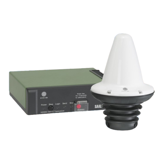
H2095C
Sailor H2095C Manuals
Manuals and User Guides for Sailor H2095C. We have
1
Sailor H2095C manual available for free PDF download: Installation Manual
Sailor H2095C Installation Manual (108 pages)
Inmarsat-C Terminal
Brand:
Sailor
| Category:
Touch terminals
| Size: 2 MB
Table of Contents
Section 1
2
Table of Contents
2
Introduction
4
Initial Inspection
4
Storage
5
Repackaging for Shipment
5
Table 1 TT-3020C Technical Specifications
9
Table 2 Inmarsat-C Protocol Support
10
Compass Safe Distance
10
Table 3 TT-3020C Power Requirements
11
Power Requirements
11
On/Off Features
11
Table 4 TT-3020C Capsat Transceiver ON/OFF Overview
13
Front Indicators and Buttons
13
Connectors
15
Table 5 TT-3020C Capsat Transceiver DC Power Connector Pin Assignment
16
Table 6 Automatic Baudrate Settings
17
Table 7 TT-3020C X3 Pin Assignment
18
I/O Connector
19
Table 8 TT-3020C X4 Pin Assignment
20
Section 2
24
Printer Port
30
Table 9 Printer Port (X5) Pin Assignment
31
Built-In GPS (Optional)
32
Grounding
32
GPS Specifications
33
Mounting Bracket
33
Table 10 GPS Specifications
33
Figure 3 TT-3020C Capsat Transceiver Mounting Plate
34
Figure 4 Front Panel of the TT-3020C Capsat Transceiver with Mounting Bracket
34
Power Requirements
36
Fuses
37
Table 11 Capsat System Component Power Requirements
37
Compass Safe Distance
38
Table 12 Capsat System Fuses
38
Table 13 Compass Safe Distance
39
Antennas
40
Figure 5 TT-3005M Maritime Antenna
40
TT-3005M Maritime Antenna
40
Table 14 TT-3005M Technical Specifications
42
Table 15 TT-3020C Capsat Transceiver Antenna Cable Types (TNC - TNC) for TT-3005M
43
Figure 6 TT-3005M 1'' Tube Mounting
44
Figure 7 TT-3005A Maritime Antenna
45
TT-3005A Maritime Antenna
45
Table 16 TT-3005A Technical Specifications
47
Table 17 TT-3020C Capsat Transceiver Antenna Cable Types
48
Figure 8 TT-3005A 1.5'' Tube Mounting
49
Figure 9 TT-3001B Opt. 001 Maritime Antenna
50
TT-3001B Maritime Antenna
50
Table 18 TT-3001B Opt. 001 Technical Specifications
51
Table 19 TT-3020C Capsat Transceiver Antenna Cable Types (N - TNC)
52
Antenna Mounting Considerations
53
Figure 10 TT-3001B-Opt. 001 1.5'' Tube Mounting
53
Figure 11 Inmarsat-C Antenna Mounting
55
Figure 12 Inmarsat-C Antenna Mounting Near Pole or Funnel
56
Safety Distance for Antenna Units
56
Table 20 Radiated Intensity
57
Connectors
58
Figure 13 TT-3606E Message Terminal
58
TT-3606E Message Terminal
58
Figure 14 TT-3606E Rear Connectors
59
Table 21 TT-3606E Power Connector
59
TT-3601E Keyboard
60
Specifications
61
Table 22 TT-3606E Message Terminal Specifications
61
Figure 15 Mounting Holes for TT-3606E
62
Mounting
62
Figure 16 TT-3606E Mounting Bracket
63
Figure 17 TT-3680B - 200W Power Supply
64
Mounting
64
TT-3680B Power Supply
64
Figure 18 Mounting Holes for TT-3680B
65
Figure 19 TT-3608A Hard Copy Printer
66
TT-3608A Hard Copy Printer
66
Figure 20 TT-3608A Paper Roll Stand
67
Mounting Plate
67
Roll Paper Stand
67
Figure 21 Mounting Holes for TT-3608A
69
Mounting
69
Figure 22 TT-3608G Remote Printer Unit
70
TT-3608G Printer Unit
70
Configuration
71
Table 23 TT-3608G DIP Switch Settings
72
Connectors
73
Installation
73
Table 24 TT-3608G Power Connector
73
Cable
74
Table 25 TT-3608G I/O Connector
74
Specifications
76
Table 26 TT-3608G Technical Specifications
76
Figure 23 TT-3042C Remote Alarm/Distress Box
77
TT-3042C Remote Alarm/Distress Box (Optional)
77
Table 27 TT-3042C and Satellite Communication Unit Inter-Connection
78
Table 28 TT-3042C Technical Specifications
79
Figure 24 TT-3042C Outline Drawing
80
Mounting
80
Figure 25 TT-3042C Outline Drawing with Console Bracket
81
Figure 26 TT-3042C Mounting Stencil
91
Figure 27 TT-3042D Remote Alarm Distress Box / Local Printer
92
TT-3042D Remote Alarm / Printer Unit
92
Configuration
93
Table 29 TT-3042D DIP Switch Settings
95
Connectors
96
Installation
96
Table 30 TT-3042D Power Connector
96
Cable
97
Table 31 TT-3042D I/O Connector
97
Specifications
99
Table 32 TT-3042D Technical Specifications
99
3.10.1 TT-3020C Transceiver
100
Distress Button Test
100
3.10.2 TT-3042C Remote Alarm/Distress Box
101
3.10.3 TT-3042D Remote Alarm Distress Box
101
Figure 28 Interconnection Diagram
103
Table 33 Antenna Voltage Configuration
108
Advertisement
Advertisement
Related Products
Sailor HC4500
Sailor HC4500B
Sailor H412
Sailor H2192
Sailor TT-3020C
Sailor Categories
Radio
Transceiver
Marine Equipment
Marine Radio
Receiver
More Sailor Manuals
Login
Sign In
OR
Sign in with Facebook
Sign in with Google
Upload manual
Upload from disk
Upload from URL