Sign In
Upload
Manuals
Brands
S&T Manuals
Desktop
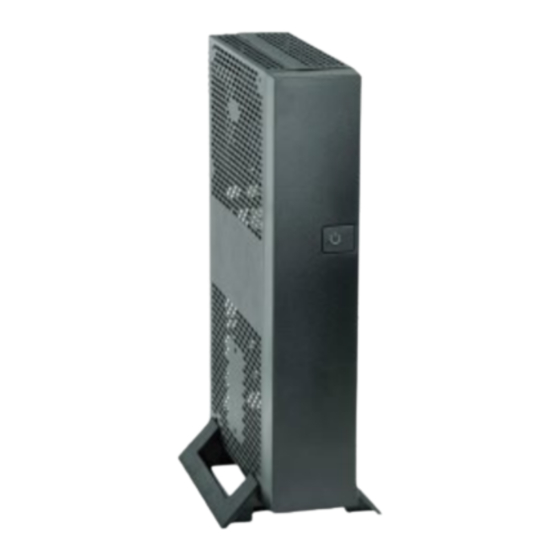
Kontron SBOX-7210
S&T Kontron SBOX-7210 Manuals
Manuals and User Guides for S&T Kontron SBOX-7210. We have
1
S&T Kontron SBOX-7210 manual available for free PDF download: User Manual
S&T Kontron SBOX-7210 User Manual (99 pages)
Brand:
S&T
| Category:
Desktop
| Size: 2 MB
Table of Contents
Symbols
6
For Your Safety
7
High Voltage Safety Instructions
7
Special Handling and Unpacking Instruction
7
Lithium Battery Precautions
8
General Instructions on Usage
8
Quality and Environmental Management
8
Disposal and Recycling
8
WEEE Compliance
8
Table of Contents
9
List of Tables
11
List of Figures
11
1 / General Safety Instructions for IT Equipment
13
Electrostatic Discharge (ESD)
15
Grounding Methods
15
Lithium Battery Replacement
15
2 / Electromagnetic Compatibility
17
Electromagnetic Compatibility (EU)
17
FCC Statement (USA)
17
EMC Compliance (Canada)
17
3 / Shipment and Unpacking
18
Unpacking
18
Scope of Delivery
18
Standard
18
Optional Parts
18
4 / System Overview
19
System Expansion Capabilities
20
System Expansion Via SATA Interface
20
System Expansion Via Mpcie Interface
20
System Expansion Via M.2 Interface
20
Front I/O Panel
21
Power Button with LED
21
Table 1: Power LED Status
21
Figure 1: Front I/O Panel
21
Rear I/O Panel
22
DC-In (Lockable DC Jack)
22
Figure 2: Rear I/O Panel
22
DVI-D
23
Line-In
23
Line-Out
23
Gbe LAN
23
Usb 3.1
23
Usb 2.0
23
Figure 3: Ethernet LED Status
23
Rs232
24
PS/2 Keyboard
24
PS/2 Mouse
24
Pcie X4 Add-On Card Slot
24
WLAN Antenna Port
24
Kensington Security Slot
24
Aperture Reserved for DP Port
24
Aperture Reserved for USB Type a Port
24
Aperture Reserved for RS232/422/485 DB9 Port
24
Internal View - - Top Side
25
Figure 4: Internal View - - Top Side (Without Cover)
25
DDR4 SO-DIMM Memory Socket
26
SATA Data Cable Connector & SATA Power Cable Connector
26
Mpcie Socket
26
Key M Socket
26
Pcie X16 Socket
26
5 / Accessing Internal Components
27
Opening and Closing the Chassis
28
Figure 5: Descrewing the Top Access Cover of the SBOX-7210
28
Figure 6: Disengaging the Top Access Cover
28
Installing SO-DIMM Memory Module(S)
29
Figure 7: Descrewing and Lifting up the Cross Bar
29
Installing a HDD / SSD
30
Installing an Mpcie Expansion Card
30
Installing an M.2 Key M SSD
31
6 / Thermal Considerations
32
Available Processors
32
Convection Cooling
32
System Clearance
32
Maximum Temperatures
32
Third Party Components
32
7 / Installation Instructions
34
System Mounting
35
Desktop Installation
35
Figure 8: Desktop Stand Kit
35
Figure 9: Aligning the Tenons of Desk Stand Brackets with the Ventilation Slots of Chassis (Horizontal)
35
Figure 10: Aligning the Tenons of Desk Stand Brackets with the Ventilation Slots of Chassis (Vertical)
36
Figure 11: Sliding the Desk Stand Brackets until Aligned with Screw Holes and Securing It (Horizontal)
36
Figure 12: Sliding the Desk Stand Brackets until Aligned with Screw Holes and Securing It (Vertical)
36
Wall Mounting
37
Figure 13: Wall Mount Kit
37
Figure 14: Hole Pattern of Wall Mount Kit for SBOX-7210
37
Figure 15: Aligning the Holes of Wall Mount Brackets and Chassis
38
DC Power Connection
39
8 / Start up
40
Connecting to DC Power Supply
40
Operating System and Hardware Component Drivers
41
9 / Maintenance and Cleaning
42
10 Technical Specifications
43
Table 2: Technical Specifications
43
Mechanical Specifications
44
Mechanical Drawing
44
Table 3: Mechanical Specifications
44
Figure 16: Mechanical Drawing
44
Environmental Conditions
45
Standards and Certifications
45
Table 4: Environmental Conditions
45
Table 5: Standards and Certifications
45
11 / Standard Interfaces - - Pin Assignments
46
DC Power Input
46
Ethernet Connector
46
USB 3.1 Port
46
Table 6: DC Power Input (See Figure 2, Pos. 1)
46
Table 7: Ethernet Connector (See Figure 2, Pos. 6)
46
Table 8: USB 3.1 Port (See Figure 2, Pos. 7)
46
USB 2.0 Port
47
DP Connector
47
Table 9: USB 2.0 Port (Figure 2, Pos. 8)
47
Table 10: DP Connector (See Figure 2, Pos. 2)
47
DVI-D Connector
48
Table 11: DVI-D Connector (See Figure 2, Pos. 3)
48
RS232 Serial Port
49
Line-In Connector
49
Line-Out Connector
49
Table 12: RS232 Serial Port (See Figure 2, Pos. 9)
49
Table 13: Line-In Connector (See Figure 2, Pos. 4)
49
Table 14: Line-Out Connector (See Figure 2, Pos. 5)
49
PS/2 Keyboard Connector
50
PS/2 Mouse Connector
50
Table 15: PS/2 Keyboard Connector (See Figure 2, Pos. 10)
50
Table 16: PS/2 Mouse Connector (See Figure 2, Pos. 11)
50
12 / Bios
51
Starting the Uefi BIOS
51
Table 17: Hotkeys Table
51
Starting the Uefi BIOS
52
Main Setup Menu
52
Table 18: Main Setup Menu Sub-Screens and Functions
52
Figure 17: BIOS Main Menu Screen System Data and Time
53
Figure 18: BIOS Main Menu Screen - - System Information
54
Figure 19: BIOS Main Menu Screen - - System Information
55
Advanced Setup Menu
56
Figure 20: BIOS Advanced Menu
57
Figure 21: BIOS Advanced Menu - - Onboard Devices Configuration
58
Figure 22: BIOS Advanced Menu - - Auto BIOS Update
59
Figure 23: BIOS Advanced Menu - - PCI Subsystem Settings
60
Figure 24: BIOS Advanced Menu - - CPU Configuration
61
Figure 25: BIOS Advanced Menu - - Drive Configuration
62
Figure 26: BIOS Advanced Menu - - SMART Setting
63
Figure 27: BIOS Advanced Menu - - Trusted Computing
64
Figure 28: BIOS Advanced Menu - - USB Configuration
65
Figure 29: BIOS Advanced Menu - - USB Configuration - - USB Port Security
66
Figure 30: BIOS Advanced Menu - - System Management
67
Figure 31: BIOS Advanced Menu - - LVDS Configuration
68
Figure 32: BIOS Advanced Menu - - Embedded Display Port Configuration
70
Figure 33: BIOS Advanced Menu - - Super IO Configuration
71
Figure 34: BIOS Advanced Menu - - Super IO Configuration - - Serial Port 1 Configuration
71
Figure 35: BIOS Advanced Menu - - Super IO Configuration - - Serial Port 2 Configuration
72
Figure 37: BIOS Advanced Menu - - Serial Port Console Configuration
74
Figure 38: BIOS Advanced Menu - - Serial Port Console Configuration - - Console Redirection Settings
75
Figure 39: BIOS Advanced Menu - - AMT Configuration
77
Figure 40: BIOS Advanced Menu - - Network Stack Configuration
78
Figure 41: BIOS Advanced Menu - - Graphic Configuration
79
Figure 42: BIOS Advanced Menu - - Intel® I210 Gigabit Network Connection
80
Figure 43: BIOS Advanced Menu - - Intel® I210 Gigabit Network Connection - - NIC Configuration
81
Figure 44: BIOS Advanced Menu - - Intel® Ethernet Connection I219-LM
82
Figure 45: BIOS Advanced Menu - - Intel® Ethernet Connection I219-LM - - NIC Configuration
83
Security Setup Menu
84
Figure 46: BIOS Security Setup Menu
84
Figure 47: BIOS Security Setup Menu - - Secure Boot Configuration
86
Figure 48: BIOS Security Setup Menu - - Secure Boot Configuration - - Key Management
87
Power Setup Menu
90
Figure 49: BIOS Power Setup Menu
90
Event Logs Setup Menu
93
Figure 50: BIOS Event Logs Setup Menu
93
Figure 51: BIOS Event Logs Setup Menu - - Change Smbios Event Log Settings
94
Figure 52: BIOS Event Logs Setup Menu - - View Smbios Event Log
94
Boot Setup Menu
95
Figure 53: BIOS Boot Setup Menu
95
Save & Exit Setup Menu
97
Figure 54: BIOS Save & Exit Setup Menu
97
Appendix A: List of Acronyms
98
Table 19: List of Acronyms
98
About Kontron
99
Advertisement
Advertisement
Related Products
S&T Kontron SBOX-5002
S&T Kontron SBOX-5210
S&T kontron COMe-cVR6
S&T Kontron KBox E-410-APL
S&T Kontron KBox B-201
S&T kontron KBox B-201-CFL
S&T kontron KBox C-103-CFL Series
S&T kontron KBox C-103-CFL-4
S&T kontron KBox C-103-CFL-2
S&T kontron KBox C-103-CFL-1
S&T Categories
Computer Hardware
Switch
Desktop
Motherboard
Single board computers
More S&T Manuals
Login
Sign In
OR
Sign in with Facebook
Sign in with Google
Upload manual
Upload from disk
Upload from URL