Sign In
Upload
Manuals
Brands
Rossato Manuals
Water Pump
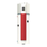
AIR COMBO EVO 200
Rossato AIR COMBO EVO 200 Manuals
Manuals and User Guides for Rossato AIR COMBO EVO 200. We have
1
Rossato AIR COMBO EVO 200 manual available for free PDF download: Installation And Maintenance Manual
Rossato AIR COMBO EVO 200 Installation And Maintenance Manual (92 pages)
Brand:
Rossato
| Category:
Water Pump
| Size: 8 MB
Table of Contents
Table of Contents
4
Introduction
10
Generalities
10
General Information and Precautions on Using the Machine
10
Responsabilities
11
Symbology and Terminology Used in the Manual
11
Table 1 - Symbology and Terminology
11
Presentation
12
Intended Use
12
Serial Number Label
12
Features
13
Regulatory References
13
Standards for Service and Proper Functioning
13
Table 2 - Standards for Service and Proper Functioning
14
Hazards and Protections
15
Prohibited Uses and Contraindications
15
Safety Protections
15
Personal Protective Equipment
15
Picture 1 - Personal Protective Equipment
15
Fire Extinguisher and First Aid
16
Handling of the Machine
17
Handling
17
Lifting
17
Packaging Removal
17
Picture 2 - Protection Removal
17
Lifting and Transporting
18
Handle for Handling
18
Inspection
19
Main Components
20
Picture 3 - AIR COMBO EVO 200
20
Table 3: Components List AIR COMBO EVO 200
21
Picture 4 - AIR COMBO EVO 200
22
Table 4: Components List AIR COMBO EVO 200
23
Picture 5 - AIR COMBO EVO 200
24
Table 5: Components List AIR COMBO EVO 200
25
Picture 6 - AIR COMBO 300
26
Table 6: Components List AIR COMBO EVO 300
27
Picture 7 - AIR COMBO 300
28
Table 7: Components List AIR COMBO EVO 300
29
Picture 8 - AIR COMBO 300
30
Table 8: Components List AIR COMBO EVO 300
31
Installation
32
Lighting
33
Functional Spaces - Installation in a Closed Space
33
Picture 9 - Functional Spaces
33
Electrical Socket
34
Condensate Drain
34
Hydraulic Connections
35
Hydraulic Connections
36
Pipe Connections
37
Picture 10 - Indicative Hydraulic Scheme (Standard Unit)
37
Table 9: Hydraulic Scheme Components (Standard Unit)
37
Picture 11 - Indicative Hydraulic Scheme (Unit with Solar Integration)
38
Table 10: Hydraulic Scheme Components (Unit with Solar Integration)
38
Aeraulic Connections
39
Possible Installations
39
Ducted Intake and Exhaust (Recommended)
39
Ducted (Conditioned) Suction
39
Ducted (Conditioned) Expulsion
40
Aeraulic Design Criteria
40
Picture 12 - Unit Connections 200
40
Picture 12A- Unit Connections 300
40
Connections
41
Picture 13 - Connections
41
Anti-Intrusion Grid for Small Animals by the Customer
43
Picture 14 - Anti-Intrusion Grid
43
Water Features
44
Table 11 - Concentration Constraints
44
Electrical Connections
45
Gestione SMART GRID - Fotovoltaico
46
Wiring Diagram- AIR COMBO EVO 200
47
Components and Wiring Diagram Description - AIR COMBO EVO 200
48
Table 12 - Components and Wiring Diagram Description - AIR COMBO EVO 200, 200S
48
Wiring Diagram- AIR COMBO EVO 300
49
Components and Wiring Diagram Description - AIR COMBO EVO 300
50
Table 13 - Components and Wiring Diagram Description - AIR COMBO EVO 300, 300S
50
Messa in Funzione
51
Preliminary Checks
52
Table 14 - Preliminary Checks
52
Checks after Installation
53
Installation Site
53
Refrigeration Circuit
53
Hydraulic Circuit
53
Aeraulic Circuit
54
Electrical Circuit
54
Voltage Verification - Absorption
55
Power Socket
55
Test Run - Water Filling before Start-Up
55
Information on Operation
56
Defrosting During Water Heating
57
TCO and ATCO
57
Basic Functions
58
Holiday Mode
58
Weekly Anti-Legionella Function
58
Electrical Resistance
58
Start-Up Report
59
Maintenance
60
Recommended Periodic Checks Sheet
60
Set-Aside
60
Power Supply
61
Electronic Anode
61
Filter Cleaning
61
Condensate Drain
62
Storage Tank
63
Tank Emptying
63
Picture 15 - Anti-Intrusion Grid
63
Replacement or Verification of Resistance
64
Picture 16 - Tank Emptying
64
Battery
65
Safety Valve
65
Expansion Valve
66
Structure
66
Start-Up after a Long Period of Inactivity
66
Residual Risk
67
Generalities
67
Danger Zone
67
Handling
67
Installation
68
Generic Risks
68
Electrical Part
68
Moving Organs
69
Refrigerant
69
Hydraulic Part
69
Disconnection
69
DISMISSION - EC WEEE Directive
70
Dismantling / Disposal
71
General Technical Data
72
Dimenions (AIR COMBO EVO 200, 200S)
72
Picture 17 - Dimenions AIR COMBO EVO 200, 200S
72
Dimenions (AIR COMBO EVO 300, 300S)
73
Picture 18 - Dimenions AIR COMBO EVO 300, 300S
73
Electrical Data
76
Operating Limits
76
SOLAR SYSTEM (by the Customer)
77
SOLAR SYSTEM (by the Customer)
78
Modbus Protocol
80
Product Data Sheet
85
Declaration of Conformity
89
Advertisement
Advertisement
Related Products
Rossato AIR COMBO EVO
Rossato AIR COMBO EVO 300
Rossato AIR COMBO EVO 200S
Rossato AIR COMBO EVO 300S
Rossato Ecodry CN+
Rossato Ecodry IN+
Rossato Air Combo 200
Rossato Air Combo 300
Rossato Air Combo PRO 100
Rossato Categories
Dehumidifier
Monitor
Fan
Heat Pump
Water Heater
More Rossato Manuals
Login
Sign In
OR
Sign in with Facebook
Sign in with Google
Upload manual
Upload from disk
Upload from URL