Sign In
Upload
Manuals
Brands
RoseWater Energy Manuals
Inverter
Hub SB20
RoseWater Energy Hub SB20 Manuals
Manuals and User Guides for RoseWater Energy Hub SB20. We have
1
RoseWater Energy Hub SB20 manual available for free PDF download: Installation Manual
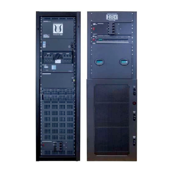
RoseWater Energy Hub SB20 Installation Manual (76 pages)
Brand:
RoseWater Energy
| Category:
Inverter
| Size: 16 MB
Table of Contents
Table of Contents
4
Introduction
8
Theory of Operation
8
Fig. 1-1, System Power Diagram - SB20
8
Table 1-1, Rosewater System Models - SB20
8
Rosewater Hub SB20 Components
9
Fig. 1-2, Rosewater Hub SB20
9
System Pre-Installation
10
Site Selection
10
Floor Plan Layout
10
Transporting and Unpacking the Cabinets
10
Recommended Installation Layout
11
Fig. 2-1, Rosewater SB20 System Clearance
11
Fig. 2-2, Rosewater SB20 and SB-EBP System Clearance
12
Fig. 2-3, System Dimensions
13
Recommended Electrical Wiring/Ratings
14
Table 2-1, Rosewater System AC Input / Output
14
System Installation
15
Single Cabinet Mounting
15
Fig. 3-1, Single SB20 Enclosure
15
System Interconnection
16
Input / Output Cabling Access
16
Wiring Gauge
16
Grounding
16
Fig. 3-2, SB20 Wiring Access Panel and Knockouts
17
AC Connection Points
18
Fig. 3-3, SB20 AC Input/Output Lugs
18
Communication Cables and Terminal Block Wiring
19
Fig. 3-4, Internet and Terminal Block Connection
19
SB20 Relay Binary Signals
20
Table 3-1, SB20 Relay Binary Signals Key
20
Fig. 3-5, Cordex Flip down Panel
21
Fig. 3-6, Removing Rear Cover
22
Fig. 3-7, Routing Binary Sense Wires
22
Extended Battery Package Installation
23
Fig. 3-8, Wire Duct Installation
23
Fig. 3-9, System Configured with Second EBP
24
SB20 to EBP Cabinet 1 Wire Connections
25
DC Connection Points, Wire Duct and Interconnect Cable Installation
25
DC Battery Cabling
25
Fig. 3-10, Battery Cable Connection Points, SB20 Cabinet
25
EBP Cabinet 1 to EBP Cabinet 2 Connections
26
Auxiliary DC Input
26
Fig. 3-11, Battery Cable Connection Points, EBP Cabinet 1
26
Solarbox 10 Layout and Mounting Detail
27
Fig. 3-12, Solarbox 10 Layout and Mounting Details
27
SB20 Auxiliary DC Input Connections for Solarbox 10
28
Fig. 3-13, Auxiliary DC Input Cable Connection Points, SB20 Cabinet
28
Fig. 3-14, 45° Bus Bar Adapters
29
Fig. 3-15, Removing Access Cover
29
Fig. 3-16, SB20 Wire 101
29
Fig. 3-17, Ground Fault Warning Label Placement
30
Fig. 3-18, Battery Sense Fuse Holder Placement
30
Fig. 3-19, Jumper Wire 194 Location
31
Fig. 3-20, Solarbox 10 RTS Placement
31
Solarbox 10 Wiring Connections
32
Fig. 3-21, Solarbox 10 Wiring Connections
32
Fig. 3-22, Solarbox 10 PV Connections
32
Fig. 3-23, Rapid Shut down (RSD) and Remote Temperature Sensor (RTS) Connections
33
Fig. 3-24, Solarbox 10 Internet 2 Connection
33
Battery Connections
34
Fig. 3-25, Representative Connection of Intercell Bars and Cordex Temperature Sensors
34
Fig. 3-26, Front Terminal Battery Hardware Stack up
35
Fig. 3-27, Battery Arrangement (200PLR Batteries with Adapters Shown)
36
System Components
37
Overview of the LCD Interface
37
Fig. 4-1, CXC-HP Controller Dashboard
37
Recitifier Features
38
Front Panel Leds
38
Fig. 4-2, Rectifier Front Panel Leds
38
Inverter Module Indicators
39
Status Leds
39
Fig. 4-3, Inverter Module Status, Power Leds
39
Fig. 4-4, Output Power Indicator Leds
39
Table 4-1, Inverter Alarm Indicators and Troubleshooting
39
T2S Inverter Control Card
40
Fig. 4-5, T2S Front Panel
40
System Start-Up and Configuration
41
Commissioning the System for the First Time
41
Tools Required
41
Prior to Start-Up
42
Starting the System
43
Fig. 5-1, Inverter Module Positions
44
Commissioning the Inverter System
45
Setting System Options
45
Fig. 5-2, Commission Inverter System Wizard
45
Commission Seed Inverters
46
Adding Inverters
46
System Functional Test
46
Synchronizing the Maintenance Bypass Switch
47
Implement the Following Steps before Switching from Inverter Mode to Bypass Mode
47
Implement the Following Steps before Switching from Bypass Mode to Inverter Mode
47
Start-Up Completion
47
Solarbox 10 Power up
48
Solarbox 10 Protective Features
49
Fig. 5-3, GFDI Fuse Holder
49
System Shutdown
50
Main Control off Push Button
50
External Emergency Shutdown
50
Cordex Controller
51
Re-Initiating the System
51
Site-Specific Cordex Settings
52
Changing Cordex CXC-HP Time and Date
52
Fig. 7-1, Time and Date
52
Create Unique Name Specific to SB20 System for Email Notification
53
Fig. 7-2, Controller Description
53
SB-EBP Battery Capacity Configuration
54
Fig. 7-3, Battery Capacity Configuration
54
Solarbox 10 Cordex Configuration Changes
55
Fig. 7-4, Custom Data Page
55
Fig. 7-5, Action Button Location
55
Fig. 7-6, Turning on PV Consumption Algorithm
55
Fig. 7-7, Configure System Page
56
Fig. 7-8, Elevated Absorption Voltage
56
Fig. 7-9, Power Flow Diagram
57
Email Notifications from the Cordex CXC-HP
58
Fig. 7-10, Set SMTP Server Password
58
Fig. 7-11, Email Destination
58
Change Cordex Login Passwords
59
Fig. 7-12, Reset Controller
59
Fig. 7-13, Change Cordex Login Password
59
SB20 Beagle Bone & Cordex Reset to Re-Establish SSH Tunnel
60
Fig. 7-14, Flip down Panel Location
60
Fig. 7-15, Beagle Bone Power Input Connector Location
60
Save System Backup on Flash Drive
61
Fig. 7-16, Flash Drive Location
61
Technical Specifications
62
SB20 Specifications
62
Table 8-1, Electrical Specifications
62
Table 8-1, Electrical Specifications, Continued
63
Table 8-2, Monitoring and Controls Specifications
64
Table 8-3, Mechanical Specifications
65
Table 8-4, Environmental Specifications
65
Solarbox 10 Specifications
66
Table 3-2, Solarbox 10 Specifications
66
Maintenance
67
Rosewater SB20 Spare Parts
67
Rosewater Annual Maintenance and Troubleshooting Guide
67
Table 9-1, SB20 Spare Parts List
67
Checkoff Sheet for Removing Failed Inverter Modules
69
Table 9-2, Reference Manuals
69
Rectifier Module Cleaning
70
CXC-HP Controller
70
Surge Suppression Replacement
71
Citel TVSS Inspection and Replacement
71
Fig. 9-1, TVSS Surge Supressors Location and Detail
71
Service Entrance Grade Strikesorb TVSS Replacement
72
Fig. 9-2, TVSS Surge Supressors and Bracket
72
Fig. 9-3, Installing the Bracket
72
Bypass Fuse Replacement
73
Fig. 9-4, Bypass Fuse Location
73
Fig. 9-5, Detail, Bypass Fuse Location
73
Battery Maintenance
74
Table 9-3, Battery Maintenance Log
75
Advertisement
Advertisement
Related Products
RoseWater Energy Categories
Inverter
More RoseWater Energy Manuals
Login
Sign In
OR
Sign in with Facebook
Sign in with Google
Upload manual
Upload from disk
Upload from URL