
Summary of Contents for RoseWater Energy Hub SB20
- Page 1 RoseWater Hub SB20 Installation Manual 043-012-C0-001, Rev. C Effective Date: February 2020...
- Page 2 RoseWater Energy adheres to ANSI Z535 and encourages special attention and care to information presented in the following manner:...
- Page 3 RoseWater Energy or your nearest RoseWater Energy representative. RoseWater Energy shall not be held liable for any damage or injury involving its enclosures, power supplies, generators, batteries or other hardware if used or operated in an unapproved manner or subject to any condition not consistent with its intended purpose, or if it is improperly installed or maintained.
-
Page 4: Table Of Contents
Table of Contents 1.0 Introduction ............................. 8 1.1 Theory of Operation ..........................8 1.2 RoseWater Hub SB20 Components ...................... 9 2.0 System Pre-Installation ......................... 10 2.1 Site Selection ............................10 2.2 Floor Plan Layout ..........................10 2.3 Transporting and Unpacking the Cabinets................... 10 2.4 Recommended Installation Layout ...................... - Page 5 Table of Contents, continued 5.6 Start-up Completion ..........................47 5.7 Solarbox 10 Power Up ......................... 48 5.8 Solarbox 10 Protective Features ......................49 6.0 System Shutdown ......................... 50 6.1 Main Control Off Push Button ......................50 6.2 External Emergency Shutdown ......................50 6.3 Cordex Controller ..........................
- Page 6 Figures Fig. 1-1, System Power Diagram - SB20....................8 Fig. 1-2, RoseWater Hub SB20 ......................9 Fig. 2-1, RoseWater SB20 System Clearance ..................11 Fig. 2-2, RoseWater SB20 and SB-EBP System Clearance ............... 12 Fig. 2-3, System Dimensions....................... 13 Fig. 3-1, Single SB20 Enclosure......................15 Fig.
- Page 7 Figures, continued Fig. 7-4, Custom Data Page ........................ 55 Fig. 7-5, Action Button Location......................55 Fig. 7-6, Turning On PV Consumption Algorithm................. 55 Fig. 7-7, Configure System Page ......................56 Fig. 7-8, Elevated Absorption Voltage ....................56 Fig. 7-9, Power Flow Diagram ......................57 Fig.
-
Page 8: Introduction
1.0 Introduction Theory of Operation The RoseWater Hub SB20 system is a Double Conversion Energy Storage System (ESS) that provides conditioned back up power to critical loads. It is intended for critical powering in large residential and small commercial applications. -
Page 9: Rosewater Hub Sb20 Components
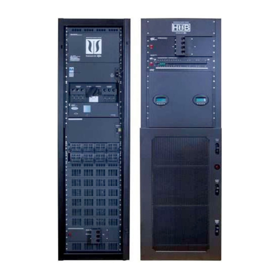
Inverter Maintenance Bypass Switch (MBS) T2S Inverter Control Card (8) Inverter Modules and Shelves Auxiliary DC Input Circuit Breaker 250A (3) 250ADC Battery Breakers - One Per (8-12) 200AH VRLA String Batteries Fig. 1-2, RoseWater Hub SB20 043-012-C0-001, Rev. C (02/2020) -
Page 10: System Pre-Installation
104°F), sheltered from rain, excessive dust and other contaminants. See Table 8-4. The batteries used in the RoseWater Hub SB20 are valve regulated lead acid and may off-gas hydrogen. The area the system is installed in must be well ventilated to prevent the build up of potentially explosive combinations of hydrogen and oxygen. -
Page 11: Recommended Installation Layout
2.0 System Pre-Installation, continued Recommended Installation Layout 2.4.1 Single Bay Layout Minimum required clearances around the cabinet (the floor must be flat and level): • Rear: 12in • Sides: 12in • Top: 16in • Front: 36in for ventilation, door clearance, and service access 4 "... -
Page 12: Fig. 2-2, Rosewater Sb20 And Sb-Ebp System Clearance
2.0 System Pre-Installation, continued 2.4.2 Double Bay Layout Minimum required clearances around the cabinet (the floor must be flat and level): • Rear: 12in • Sides: 12in • Between Cabinets: 4in • Top (excluding wiring duct): 16in • Front: 36in for ventilation, door clearance, and service access 4 "... -
Page 13: Fig. 2-3, System Dimensions
2.0 System Pre-Installation, continued (Wire duct with SB-EBP - optional) 100" (with cabling duct and proper clearance) 88" (with cabling duct) 84.5" 4" 28.1" 28.1" (SB-EBP - optional) Fig. 2-3, System Dimensions 043-012-C0-001, Rev. C (02/2020) -
Page 14: Recommended Electrical Wiring/Ratings
Any disconnect must be installed in accordance with NEC code 706.7 Disconnecting Means. Disconnect must be within 5 ft of ESS. • In addition to these considerations, RoseWater recommends that the installer review the RoseWater HUB SB20 System Wiring Diagram prior to installation (p/n 043-012-08). 043-012-C0-001, Rev. C (02/2020) -
Page 15: System Installation
3.0 System Installation Single Cabinet Mounting The cabinet must be fixed in place to the floor by following the steps outlined below. Prior to installation, verify that there is sufficient space between and around the cabinet (see Section 2.4, Recommended Installation Layout). -
Page 16: System Interconnection
3.0 System Installation, continued System Interconnection The RoseWater Hub SB20 system is pre-configured from the factory for a single AC feed per phase for rectifiers, inverters and the maintenance bypass switch. The installer is responsible for connecting the following: • Utility input (240V Split Phase, or 2 legs of 208V) to the system (120V line to neutral). -
Page 17: Fig. 3-2, Sb20 Wiring Access Panel And Knockouts
3.0 System Installation, continued AC INPUT 2" KNOCKOUT AC OUTPUT 2" KNOCKOUT REMOTE INTERFACE CONTROL WIRES (OPTIONAL) ETHERNET Fig. 3-2, SB20 Wiring Access Panel and Knockouts 043-012-C0-001, Rev. C (02/2020) -
Page 18: Ac Connection Points
3.0 System Installation, continued AC Connection Points WARNING! GENERAL HAZARD The following connections must only be installed by a certified electrician. • Access to AC Input/Output connections is through the front of the cabinet. • AC wires must be fed through the conduit knockouts on top of the cabinet. •... -
Page 19: Communication Cables And Terminal Block Wiring
3.0 System Installation, continued Communication Cables and Terminal Block Wiring INTERNET CONNECTION DC CONTROL TERMINAL BLOCK Fig. 3-4, Internet and Terminal Block Connection SB20 Internet Connection The SB20 is equipped with an RJ45 Ethernet connector for internet connectivity. SB20 DC Control Terminal Blocks The SB20 DC Control Terminal block is used to land remote interface control wires from outside the system. -
Page 20: Sb20 Relay Binary Signals
3.0 System Installation, continued 3.5.1 SB20 Relay Binary Signals The Rosewater SB20 is capable of sending binary signals to an external monitoring system to indicate the status of the Energy Storage System. The Cordex Controller L-ADIO has four designated relays, K9 to K12 that are programmed to respond to specific system conditions. -
Page 21: Fig. 3-5, Cordex Flip Down Panel
3.0 System Installation, continued Relay State Transfer Delays During light load discharge, at runtime reporting transition points, relay states may toggle due to normal measurement uncertainties. It is recommended that reporting of state changes be delayed or filtered. Binary Relay Contact Specifications Form C dry contact NC, COM, NO. -
Page 22: Fig. 3-6, Removing Rear Cover
3.0 System Installation, continued To gain access, the rear cover over the low voltage DC connections will need to be removed. Route Control Wires Fig. 3-6, Removing Rear Cover Binary relay sense wires can enter the SB20 on the top front corner through the same hole as the customer Ethernet cable. -
Page 23: Extended Battery Package Installation
3.0 System Installation, continued Extended Battery Package Installation The SB20 System has the option for up to two Extended Battery Packages (EPB). Custom wire duct and wire kits are provided to connect the EBP. The EBP cabinet must be fixed in place to the floor by following the steps outlined below. Prior to installation, verify that there is sufficient space between and around the cabinet (see Section 2.4, Recommended Installation Layout). -
Page 24: Fig. 3-9, System Configured With Second Ebp
3.0 System Installation, continued 3.6.1 Configurations with EBP2 In the event a second Extended Battery Package (EPB) cabinet is used, it will be connected via custom wire ducting and wire kits as shown below. Verify that the part numbers for the ducting and kits used match the part numbers shown. The second EBP cabinet will be installed following the same procedure(s) as the first EBP cabinet. -
Page 25: Sb20 To Ebp Cabinet 1 Wire Connections
3.0 System Installation, continued SB20 to EBP Cabinet 1 Wire Connections 3.7.1 DC Connection Points, Wire Duct and Interconnect Cable Installation Route the double 4/0 bus interconnect cables and frame ground from the SB20 to the EBP and connect per figure below. Use the wire tie mounts inside the duct for cable management. -
Page 26: Ebp Cabinet 1 To Ebp Cabinet 2 Connections
3.0 System Installation, continued The EBP comes with the Alarm and LED lights already terminated in the EBP side (see Fig. 3-8) Route the Alarm Wires and LED light wires from the EBP to the SB20 and connect. Use the wire tie mounts inside the duct for cable management. -
Page 27: Solarbox 10 Layout And Mounting Detail
3.0 System Installation, continued 3.7.5 SolarBox 10 Layout and Mounting Detail NOTICE: The Solarbox 10 may be mounted on either 12" stud or 16" stud walls. 30" MIN TO ONE WALL FOR SERVICE ACCESS MAY BE LEFT OR RIGHT OF SBX10 2"... -
Page 28: Sb20 Auxiliary Dc Input Connections For Solarbox 10
3.0 System Installation, continued 3.7.6 SB20 Auxiliary DC Input Connections for Solarbox 10 Conduit and wiring should be installed by a qualified electrician. WARNING! ELECTRICAL HAZARD Verify the SB20 is powered down completely, and battery circuit breakers and auxiliary DC input circuit breaker are turned off. -
Page 29: Fig. 3-14, 45° Bus Bar Adapters
3.0 System Installation, continued Use a torque wrench with a 9/16" socket to secure the hardware to 15 ft-lbs. (A 15mm socket is required on the Gigavac contactor metric bolt. Torque to 15 ft-lbs.) Fig. 3-14, 45° Bus Bar Adapters The Solarbox 10 uses Outback Flexmax 100 charge controllers equipped with a Ground Fault Detection Interrupter (GFDI). -
Page 30: Fig. 3-17, Ground Fault Warning Label Placement
3.0 System Installation, continued Place Warning Label (p/n 375-0313-01-00) that reads "WARNING: WHEN A GROUND FAULT IS INDICATED, BATTERY TERMINALS AND CONNECTED CIRCUITS MAY BE UNGROUNDED AND HAZARDOUS." below the SB20 Warning label. See location in Fig. 3-17. Fig. 3-17, Ground Fault Warning Label Placement The Solarbox 10 battery voltage sense wires require an inline 3A fuse on the +48VDC battery bus. -
Page 31: Fig. 3-19, Jumper Wire 194 Location
3.0 System Installation, continued The SB20 can monitor the Solarbox 10 Auxiliary DC Input Alarm. To enable this capability, Alarm Terminal Block jumper wire 194 must be removed from TB (terminal block) 24 and 25 and replaced with the alarm wires 332 & 333 from the Solarbox 10 (this connection is non-polarized). -
Page 32: Solarbox 10 Wiring Connections
3.0 System Installation, continued 3.7.7 Solarbox 10 Wiring Connections Conduit and wiring should be installed by a qualified electrician. Refer to Solarbox wire diagram 043-0001-08 and the following figures for wire connections. Fig. 3-21, Solarbox 10 Wiring Connections PV INPUTS Fig. -
Page 33: Fig. 3-23, Rapid Shut Down (Rsd) And Remote Temperature Sensor (Rts) Connections
3.0 System Installation, continued Fig. 3-23, Rapid Shut Down (RSD) and Remote Temperature Sensor (RTS) Connections The Rapid Shut Down function is optional, but the requirement is dependent on the NEC version adopted in the state in which the system is installed. A jumper wire placed between the yellow and purple terminal blocks will bypass the RSD function. -
Page 34: Battery Connections
3.0 System Installation, continued Battery Connections WARNING! ELECTRICAL HAZARD Observe the following precautions to reduce the risk of electrical shock when maintaining batteries: • Ensure that all breakers are OFF. • Remove all personal metal objects (watches, rings, etc.). • Always use insulated tools. -
Page 35: Fig. 3-26, Front Terminal Battery Hardware Stack Up
3.0 System Installation, continued Newer SB20s are compatible with EnergyCell 200NC or EnergyCell 200PLR batteries. See hardware stack up below for correct installation. EnergyCell 200NC CORDEX TEMPERATURE SENSOR INTERCELL BAR 1/4-20 X 3/4" BOLT SPLIT WASHER FLAT WASHER BATTERY CABLE BATTERY TERMINAL BATTERY TERMINAL EnergyCell 200PLR... -
Page 36: Fig. 3-27, Battery Arrangement (200Plr Batteries With Adapters Shown)
3.0 System Installation, continued WARNING! ELECTRICAL HAZARD Installing the intercell bar between batteries 3-4, 7-8, and 11-12 WILL energize the control circuit. DO NOT install the intercell bar between these batteries until the system is ready for the initial system startup. For 200NC batteries, the retaining brackets must be bolted in place. -
Page 37: System Components
4.0 System Components Overview of the LCD Interface The LCD screen is a touch-sensitive color panel on the front of the controller. The display is always on when the controller is first powered up but after 20 minutes of inactivity the user will be logged out and the display will be turned off to prevent the LCD screen from wearing out. -
Page 38: Recitifier Features
4.0 System Components, continued Recitifier Features 4.2.1 Front Panel LEDs The front panel LEDs indicate the rectifier status summary and patterned response to Locate Module command. Refer to the Cordex CXRF 48-2.4 kW manual for further details. LEDs Fig. 4-2, Rectifier Front Panel LEDs ALARM / FAULT (1) The red LED is on during an active Module Fail alarm if the module is unable to source power due to a fault condition. -
Page 39: Inverter Module Indicators
4.0 System Components, continued Inverter Module Indicators AC Output DC Input AC Input Fig. 4-3, Inverter Module Status, Power LEDs Inverter Status LED Description Remedial Action No input power or forced stop Check AC Input Permanent green AC Input OK, normal operation None required Flashing green Inverter OK but conditions are not... -
Page 40: T2S Inverter Control Card
4.0 System Components, continued T2S Inverter Control Card The CXC-HP unified system controller monitors and manages inverter modules by communicating with the T2S inverter control card. The T2S may be useful in troubleshooting inverter alarms. LEDs 1 through 3 on the front panel of the T2S indicate the following alarm conditions: •... -
Page 41: System Start-Up And Configuration
Any tools used to service battery terminals or a DC bus should be insulated. WARNING! ELECTRICAL HAZARD The RoseWater Hub SB20 must have no power (utility breaker OFF and locked out) and no inverter modules installed prior to start up. -
Page 42: Prior To Start-Up
5.0 System Start-Up and Configuration, continued 5.1.2 Prior to Start-Up 1. Verify that the RoseWater Hub SB20 system is mechanically secured to the floor. 2. Verify that the clearances around the SB20 system meet the minimum requirements. 3. Verify that the controller breakers inside the Cordex flip down panel are on. -
Page 43: Starting The System
5.0 System Start-Up and Configuration, continued Starting the System 1. Install the last intercell connectors on each of the battery strings from the bottom shelf to the top shelf (1-3). 2. Before proceeding, verify the polarity of the DC battery shelves and use a voltmeter to ensure each battery string is 48VDC nominal. -
Page 44: Fig. 5-1, Inverter Module Positions
5.0 System Start-Up and Configuration, continued 16. Turn on AC Input Aux CB. Plug in Battery Cover LED light connector. Observe Blue LED lights turn on. (Install covers on battery terminals and install battery compartment cover after start up procedure is complete.) 17. -
Page 45: Commissioning The Inverter System
5.0 System Start-Up and Configuration, continued Commissioning the Inverter System There are three stages to commissioning an inverter system: 1. Setting system options 2. Commissioning seed inverters 3. Adding inverters The wizard automatically goes to stage two, upon completion of stage one. 5.3.1 Setting System Options This wizard requests configuration information such as: •... -
Page 46: Commission Seed Inverters
5.0 System Start-Up and Configuration, continued 5.3.2 Commission Seed Inverters The second stage of commissioning involves inserting one seed inverter for each phase. The seed inverter provides a reference for all other inverters in the same phase so they can learn their power configuration and the phase shift. The commission wizard steps the user through the process. -
Page 47: Synchronizing The Maintenance Bypass Switch
5.0 System Start-Up and Configuration, continued Synchronizing the Maintenance Bypass Switch CAUTION! NEVER operate the Maintenance Bypass Switch without first verifying that the AC Input Breaker is turned ON. Inverters must be synchronized to the line - all status LEDs on the inverters must be green. -
Page 48: Solarbox 10 Power Up
5.0 System Start-Up and Configuration, continued Solarbox 10 Power Up Power up of Solarbox 10 must be conducted by a qualified electrician. 1. With all Solarbox 10 circuit breakers turned off, power up the SB20. Verify all SB20 circuit breakers are turned on. See Section 5.2. -
Page 49: Solarbox 10 Protective Features
5.0 System Start-Up and Configuration, continued Solarbox 10 Protective Features Once power up of the Solarbox 10 is complete, the unit is configured for daily harvest of solar power to help support your critical loads. Solarbox 10 is equipped with protective features to disable this harvest in the event of a system ground fault (GFDI), a PV array arc fault (AFCI), or a commanded emergency rapid shutdown (RSD). -
Page 50: System Shutdown
• All communications in the cabinets are shut down. • If Solarbox 10 option is installed, Solarbox 10 will shut down. The RoseWater Energy Hub system can remain in the powered off state indefinitely. However, the batteries will self- discharge over time. -
Page 51: Cordex Controller
Re-initiating the System After a system shutdown, the RoseWater Energy Hub system can only be restarted by the green Main Control ON push button. When the Main Control ON button is pushed, the RoseWater Energy Hub performs the following actions: •... -
Page 52: Site-Specific Cordex Settings
7.0 Site-Specific Cordex Settings Accessing Cordex Web Interface through the local network: 1. Connect your computer to the same local network as the SB20 is plugged into. 2. Go to the SB20 Cordex LCD touch screen and hit the Shortcuts then the Ethernet tiles. 3. -
Page 53: Create Unique Name Specific To Sb20 System For Email Notification
7.0 Site-Specific Cordex Settings, continued 7.2 Create Unique Name Specific to SB20 System for Email Notification A unique name needs to be created specific to this SB20 system. This name will be used in Email notifications to help identify the unit. The name has been partially created at the factory but additional recognizable information needs to be added when the unit reaches its final location. -
Page 54: Sb-Ebp Battery Capacity Configuration
7.0 Site-Specific Cordex Settings, continued 7.3 SB-EBP Battery Capacity Configuration The standard battery capacity of an SB20 with three 48VDC strings of 200NC batteries is 534 Ah. When a SB-EBP is installed the battery capacity must be adjusted to a new value. This will affect estimated battery run time. With the addition of one SB-EBP, the capacity should be 2 x 534 Ah = 1068 Ah. -
Page 55: Solarbox 10 Cordex Configuration Changes
7.0 Site-Specific Cordex Settings, continued Solarbox 10 Cordex Configuration Changes The SB20 Cordex controller must have the following or later versions: • Operating system: v6.0 • Software: v6.0 • Base configuration file: exportconfig_SB20rev11.xml (Check with factory for details.) To use solar power from the Solarbox 10, the SB20 configuration must be changed to consumption mode. 1. -
Page 56: Fig. 7-7, Configure System Page
7.0 Site-Specific Cordex Settings, continued 4. Navigate to System / RosewaterSB20 (DC System 48V/5636) / Configure System and change Float Voltage to 53.50V. Fig. 7-7, Configure System Page 5. Navigate to System / Rosewater SB20 (DC System 48V5636) / System Functions / Charging and change Elevated Absorption Voltage to 57.20V. -
Page 57: Fig. 7-9, Power Flow Diagram
7.0 Site-Specific Cordex Settings, continued 7. Navigate to Power Flow Diagram on Cordex interface. Fig. 7-9, Power Flow Diagram NOTICE: If it is a sunny day, you should be able to observe PV Charger DC current input to the system. It will be used to maintain the batteries and source power to the critical loads. -
Page 58: Email Notifications From The Cordex Cxc-Hp
7.0 Site-Specific Cordex Settings, continued Email Notifications from the Cordex CXC-HP NOTICE: Internet connection to home network must be available. Notifications can be distributed from any email server that you can access. The following example shows how to use the free Gmail server. -
Page 59: Change Cordex Login Passwords
7.0 Site-Specific Cordex Settings, continued Go to (/Controller/Controller Status) Fig. 7-12, Reset Controller After the Cordex resets go back to (/Controller/Configure Controller/Communications/Email) Press the Send Test Email button (just below the title block in the pic above). If you don’t receive a test notification within five minutes, you may need to reduce the security settings to allow mail from the Cordex through. -
Page 60: Sb20 Beagle Bone & Cordex Reset To Re-Establish Ssh Tunnel
7.0 Site-Specific Cordex Settings, continued SB20 Beagle Bone & Cordex Reset to Re-establish SSH Tunnel The SB20 must be plugged into the Internet though the customers router. (See SB20 manual Section 3.5) When the SB20 is connected to the internet, the SSH tunnel should be established automatically. Call SB20 Technical Support to verify that SSH tunnel is established at the site location. -
Page 61: Save System Backup On Flash Drive
7.0 Site-Specific Cordex Settings, continued 3. Re-insert Beagle Bone power input connector. Indicator lights should power back on. 4. Perform a soft reset on the Cordex by going to (/Controller/Controller Status). 5. Wait approximately 5 minutes. 6. Call SB20 Technical Support to verify that the SSH tunnel is established at the site location. Save System Backup on Flash Drive After site specific changes are made, save Backup File on the flash drive provided inside the flip-down panel of the Cordex controller. -
Page 62: Technical Specifications
8.0 Technical Specifications SB20 Specifications SB20 Electrical Specifications System Input Power Utility AC Input Voltage 120/240V or 120/208V 3 Wire + Ground Utility AC Input Current 100A Max, PER Phase , 0.8PF Utility AC Input Frequency 60Hz 125A External feed Circuit Breaker or fuse (2 pole). Circuit capable of delivering no more than 5KA short-circuit current Utility AC Input RMS symmetrical amperes, 120 Volts. -
Page 63: Table 8-1, Electrical Specifications, Continued
8.0 Technical Specifications, continued SB20 Electrical Specifications Inverters Inverter System Alpha Inverter Module 2500 Inverter QTY Up to (8) Inverter Arrangement Two shelves, one phase per shelf (L1 and L2) Input Voltage (VAC) 120V (range 90V – 140V adjustable) Output Voltage (VAC) 120V Battery Voltage (VDC) 48 nominal (range 40V –... -
Page 64: Table 8-2, Monitoring And Controls Specifications
8.0 Technical Specifications, continued SB20 Monitoring and Controls Specifications Interface Inverter and DC Distribution Cordex CXCHP Remote (LAN) Access Equipped for single network connection to Cordex controller web server Local Interface CXCHP touchscreen Cordex CXC HP DC Current Monitoring via CXC HP (1) Rectifier Output, (1) Inverters, (1) Batteries Programmable AUX contact available for generator start on low DC bus. -
Page 65: Table 8-3, Mechanical Specifications
8.0 Technical Specifications, continued SB20 Mechanical Specifications Enclosure System Dimensions (inches) (W x D x H) 28.1W x 26.3D x 84.5H Main Enclosure: 790lb Enclosure Weight Without Batteries (lbs) Battery Expansion: 800lb estimate Enclosures to be covered to prevent any electrical touch Electrical Touch Hazard hazard without tool access by service technician Mounting... -
Page 66: Solarbox 10 Specifications
8.0 Technical Specifications, continued Solarbox 10 Specifications Solarbox 10 Specifications Part Number 043-00001-20 Model Number SBX10-300VDC-AFCI Description SBX10,2FM100,AFCI,10kW,-GND,ALPHA Nominal Battery System Voltage 48VDC Maximum Continuous Output Current (2x) 100A Maximum Input Current (Short-Circuit) (2x) 64A Maximum Array (STC Nameplate) (2x) 6000W (charging output limited to 100A at battery voltage) Maximum PV System Voltage 300VDC Operating Input Voltage Range... -
Page 67: Maintenance
9.0 Maintenance RoseWater SB20 Spare Parts SB20 Spare Parts List Recommended Part Number Description Qty. Used Spare Qty. 014-201-20 INVERTER MODULE, AIM2500,48/120,2000W ATL7400026 INVERTER MODULE FAN ASSY,AIM2500 ATL0100003-001 RECTIFIER MODULE,CXRF-HP 48-2.4KW,ROHS6 747-028-20-A001 REMOTE TEMP SENSOR,1/4" BATTERY STUD, 12' 460-278-19 DIN RAIL FUSE,5MM X 20MM,3A 250V,SLOW 460-353-19 IN LINE FUSE,1/4"X1-1/4",3A 250V,125VDC,SLOW ATL4600112... - Page 68 9.0 Maintenance, continued 2. Before starting service, inspect the Inverter system, noting the status of the lights on each inverter module. Follow troubleshooting guide for the items noted. Make entries in the Maintenance Log. 3. Before starting service, note any events that are of concern in the Cordex Statistics and Events logs. Follow troubleshooting guide for the items noted.
-
Page 69: Checkoff Sheet For Removing Failed Inverter Modules
9.0 Maintenance, continued 2. Simulate an outage by shutting off the AC input. Watch the battery string voltage during this test. 3. Let the Rosewater Hub operate in the backup mode for approximately 10 minutes, while checking for alarms generated by the system. 4. -
Page 70: Rectifier Module Cleaning
9.0 Maintenance, continued 2. Record Cordex alarms. See Section 5.2 Starting the System, item 7 for instructions to connect a browser to the Cordex. Navigate to Active Alarms and record all below or capture the screen: Menu Path: Alarms / Active Alarms 3. -
Page 71: Surge Suppression Replacement
9.0 Maintenance, continued Surge Suppression Replacement WARNING! ELECTRICAL HAZARD There may still be live parts inside the system and shock hazards may be present throughout this procedure. 9.3.1 Citel TVSS Inspection and Replacement 1. Put system into Bypass Mode (see Section 5.5.1). 2. -
Page 72: Service Entrance Grade Strikesorb Tvss Replacement
9.0 Maintenance, continued 9.3.2 Service Entrance Grade Strikesorb TVSS Replacement Service is only required in the case of TVSS failure (failure will cause the input circuit breaker to trip). Verify the spare parts are available on site. Critical loads must be shut down. Front Access Replacement This is the preferred replacement procedure. -
Page 73: Bypass Fuse Replacement
9.0 Maintenance, continued Bypass Fuse Replacement 1. Verify the spare parts are available on site. 2. Critical loads must be shut down. 3. Shut down system by pushing the Main Control OFF button. 4. Remove all AC and DC power from the system; observe proper lockout tag procedures. 5. -
Page 74: Battery Maintenance
9.0 Maintenance, continued Battery Maintenance To help identify batteries approaching end of life in an operating power system, Evaluation Procedure 1 should be performed at each maintenance interval. For batteries not installed in an operating power system, Evaluation Procedure 2 or 3 may be performed. -
Page 75: Table 9-3, Battery Maintenance Log
9.0 Maintenance, continued Evaluation Procedure #1 Evaluation Procedure #2 Evaluation Procedure #3 Conductance VDC 24 Conductance VDC @ Float VDC 24 mhos @ Hour mhos @ 100A after Hour OCV 77°F/25°C 77°F/25°C 10 seconds Load Table 9-3, Battery Maintenance Log 043-012-C0-001, Rev. - Page 76 Visit us at www.rosewaterenergy.com Due to continuing product development, RoseWater Energy reserves the right to change specifications without notice. 043-012-B0-001, Rev. C (02/2020) Copyright © 2020 RoseWater Energy. All Rights Reserved.
Need help?
Do you have a question about the Hub SB20 and is the answer not in the manual?
Questions and answers