Sign In
Upload
Manuals
Brands
Rohde & Schwarz Topex Manuals
Network Router
Bytton LTE
Rohde & Schwarz Topex Bytton LTE Manuals
Manuals and User Guides for Rohde & Schwarz Topex Bytton LTE. We have
1
Rohde & Schwarz Topex Bytton LTE manual available for free PDF download: User Manual
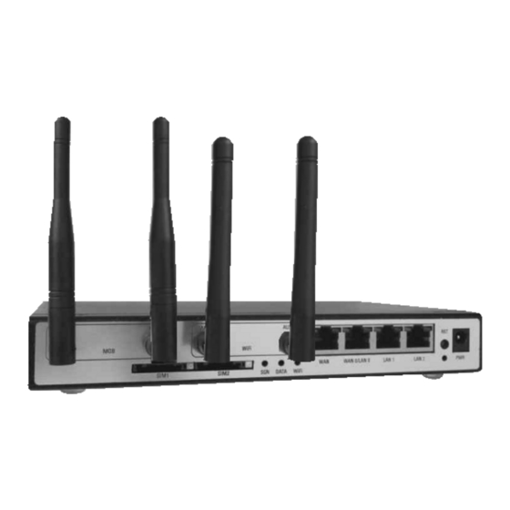
Rohde & Schwarz Topex Bytton LTE User Manual (290 pages)
Industrial-grade Cellular Router for 3G+/4G Networks
Brand:
Rohde & Schwarz Topex
| Category:
Network Router
| Size: 9 MB
Table of Contents
Table of Contents
7
1 Introduction
16
Figure 1-1: Bytton LTE Featuring One or Two RS-232 Ports (SER1, SER2)
16
Figure 1-2: Photo of Bytton LTE with Two Serial Ports, FXS Phone Interface, Two SIM Cards, Wi-Fi and Slot for USB
18
Figure 1-3: Drawing and Photo of Antenna Diversity: up to Two Antennas for Mobile and Wi-Fi
18
2 Package Content
19
Figure 2-1: Illustrations of the Content of the Package of Bytton ICR
19
3 Equipment Functions and Identification
20
What Is Bytton ICR
20
Figure 3-1: Connecting the Local Clients to Internet Via Broadband Mobile Data Network
20
Figure 3-2: General (Field) Applications of the Bytton ICR Wireless Router
20
Figure 3-3: Bytton ICR Acts as a Router for Wired and Wireless Local Networks
20
Figure 3-4: Firewall Function of Bytton ICR
21
Identification of the Equipment Model/Variant
22
Significance of Labels
22
Software Information
25
4 Installation
27
Establishing the Best Location
27
Mounting (Hardware Installation)
27
Horizontal Mounting
27
Figure 4-1: Horizontal Mounting of Bytton ICR
27
Rail Mounting
28
Figure 4-2: Schematic of Bytton ICR Attached to a DIN Rail
28
Figure 4-3: Attach the Mechanical Adapter to the Back of the Case of Bytton ICR
29
Figure 4-4: Attach the Equipment to the DIN Rail, by Means of the Adapter
29
Figure 4-5: Bytton LTE Fastened to the DIN Rail
29
Identification of Connectors
30
Figure 4-6: Image of Indicators and Connectors of Bytton ICR with One Serial Interface
30
Figure 4-7: Drawing of Indicators and Connectors of an "Advanced" Bytton LTE, Fully Equipped
30
Connecting the Data Cables
32
Figure 4-8: Connecting All the Cables and Accessories to Bytton
32
Figure 4-9: Connecting the LAN Cables
32
Figure 4-10: Connecting the WAN Cable
34
Figure 4-11: Connecting the Serial Cables to Bytton LTE
36
Configuring and Installing the SIM Card (S)
37
Figure 4-13: Location of the One or Two Slots for SIM Cards
38
Connecting the External Antennas
40
Figure 4-14: Illustration of the Four Steps Sequence of Inserting the SIM Card into Bytton LTE
40
Figure 4-15: Inserting the Connector of the GSM/3G Mobile Antenna
41
Figure 4-16: Inserting the Connectors for the LTE Mobile Antennas (One or Two Pcs.)
41
Figure 4-17: Bytton LTE with Four Antenna Connectors, Two for LTE (4G Mobile) and Two for N-Type Wifi Access Point
41
Figure 4-17: Attachment of a Single Wifi Stick Antenna
42
Figure 4-18: Attachment of the Two Wifi Antenna for N-Type Wireless AP
42
Power up
43
Status Indicators
44
Figure 4-19: Location of Indicator Leds
44
5 Configuration
45
Using the Web Interface
45
Set up a Connection
45
Figure 5-1: Go to "Network and Internet" in the Control Panel
45
Figure 5-2: Go to "Network and Internet" to Create a Network Connection for Bytton LTE
46
Automatic IP Address
47
Figure 5-3: Setting the Network Properties for the ETH Connection to Bytton
47
Figure 5-4: Setting Automatically IP for the Connection to Bytton
47
Manual IP Settings
48
Figure 5-5: Manually Establishing IP Parameters for the Connection to Bytton
48
First Connection
49
Secure Connection HTTPS
49
Figure 5-6: Enter the Default IP Address of the Web Page into Your Browser
49
Figure 5-7: Changing the Default IP Address of Bytton LTE
49
Figure 5-8: Security Alert for the Https Connection
49
Figure 5-9: Warning about the Certificate of a Trusted Website
50
Figure 5-10: Security Alert from Internet Explorer about the Secure Connection (Encrypted Page)
50
Log-In to Bytton LTE
51
Figure 5-11: Connecting to the Configuration Web Page of Bytton LTE
51
Figure 5-12: Authentication Required - Enter User Name (Admin) and Password
51
Figure 5-13: Indication of Remote User and Location
51
Figure 5-14: Login Error Message - Unauthorized
51
Multiple Log-In to the Web-Interface of Bytton
52
Figure 5-15A: Log-In as "Admin
52
Figure 5-15B: Log-In as "Superuser
53
MENU Items
55
Figure 5-16A: Web Configuration Page, Listing Sub-Menu Items for "Admin
55
Figure 5-16B: Web Configuration Page, Listing All Sub-Menu Items for "Superuser
56
Lan
59
IP Settings
59
Figure 5-17: LAN Configuration Webpage, with Subpages
59
Figure 5-18: LAN Configuration Page, IP Settings
59
Figure 5-19: Changing the Default IP Address of Bytton on the LAN - Several Examples
60
Figure 5-20: LAN Configuration Page, Additional IP Address Tables
60
Figure 5-21: LAN Configuration Page, Access the Link Loopback
64
Figure 5-22: LAN Configuration Page, Set IP for the Loopback Test Link
64
Software Configuration of the ETH Switch
65
Using "SW (LAN1, LAN2)" to Disable Two Local Ports
74
Commit
79
Figure 5-23: Commit Settings Command - Aspect of Progress Bar "Saving Changes
79
DHCP Settings
80
Figure 5-24: LAN Webpage - DHCP Server
80
Figure 5-25: Open Network and Sharing Center to Verify the Assignment of IP Addresses
81
Figure 5-26: the General Tab of the Connection to Bytton LTE Shows Its Current State
81
Figure 5-27: the Details Tab of the Connection to Bytton LTE Shows Its IP Address
81
Figure 5-28: Using the "Forward To" Option for DHCP Server in LAN Configuration Webpage
82
Figure 5-29: Select Manual or Automatic for DSN Servers
82
Figure 30A: When Automatic Option Is Chosen, the Next Fields Are Inactive (Grey Color)
82
Figure 5-30B: Select Manual Instead of Automatic for DSN Servers
82
Figure 5-31: Click the Link "Filter List MAC" to Use this Feature
83
Figure 5-32: the MAC List, Which Is Empty in the Beginning
83
Figure 5-33: Adding and Editing Entries in the Table "Filter List MAC
83
Figure 5-34: Defining MAC Entries in the Table "Filter List MAC
84
Figure 5-35: Defining MAC Entries in the Table "Filter List MAC
87
Figure 5-36: Editing MAC Entries in the Table "Filter List MAC
87
Wifi Settings
88
Figure 5-37: the LAN Page for Wifi Settings
88
Figure 5-35: Select the Radio Channels of the Wifi Access Point
91
Figure 5-38: Select and Set up the WEP Security Features
92
Figure 5-39: Select and Set up the Advanced WPA Security Features
92
Figure 5-40: Enable and Configure MAC Security for Wifi
93
802.1X" Settings
94
Figure 5-41: 802.1X Settings, by Default Disabled
94
Figure 5-42: Enable and Configure Settings for 802.1X EAPOL
95
Figure 5-43: Embedded Help for the Parameters of 802.1X Authentication for EAPOL
96
Bridge
97
Figure 5-44: "Bridge" Configuration Page, Empty in the Beginning
97
Figure 5-45: Edit an Entry in the "Bridge" Table
98
Figure 5-46: Several Entries in the "Bridge" Table
99
Figure 5-47: Bridges Showing up in "Bridge Status
99
Figure 5-48: the same Bridges in the "Routes" Table
99
Figure 5-49: Details of Bridges in the "Bridge Status" Table
100
Interface Status" and "Test Net" Features
101
Figure 5-50: the Window "Interface Status" and the Corresponding Link Present in Several Configuration
101
Figure 5-51: the Link "Test Net" at the Bottom of the "Interface Status" Page
109
Figure 5-52: Features of The"Test Net" Page
109
Figure 5-54: Commands Available in "Network Tests" Page
114
Vlan
115
Figure 5-55: the "VLAN" Page with Several Virtual Lans Defined
115
ETH Ports
120
Figure 5-56: the "ETH Ports" Page for Physical Configuration of Ethernet Ports
120
Figure 5-56: the "ARP Table" with Multiple Entries
126
Mtu
127
Figure 5-57: the "MTU" Window of the LAN Configuration Page
127
Wan
131
Settings
131
Figure 5-58: the WAN Webpage
131
Figure 5-59: Webpage for Setting WAN Interface Type and Failover
131
Figure 5-60: Example of Setting up Primary and Secondary WAN Interfaces, Using Failover
135
Figure 5-61: Output Route Via Cabled Ethernet Connection Wan
135
Figure 5-62: Output Route Via Wireless Connection Ppp1
135
WAN Management
136
WAN Port
137
Figure 5-63: Webpage for Setting up WAN Port in the WAN Settings
137
Figure 5-64: Selection of Address Type (Automatic) for WAN Port in the Page for WAN
137
Figure 5-65: Examples of Setting Static Address for WAN Eth Interface in the WAN Pages
138
Figure 5-66: Setting the Name Servers for Static IP on the ETH Interface for WAN
138
Figure 5-67: Settings for PPP over Ethernet Connection in Webpage for WAN
139
Ppp
140
Figure 5-68: Settings for PPP Link for the Embedded Radio Modem of Bytton ICR
140
Figure 5-69A: Settings for PPP Link in Case of Dual-SIM Bytton Equipment
141
Figure 5-69B: Settings for the Second SIM of the PPP Wireless Link, in Case of Dual-SIM Bytton LTE Device
141
PPP Advanced Settings
143
Figure 5-70: Advanced PPP Settings for the Embedded Modem of Bytton LTE
143
Figure 5-71: PPP Advanced Settings -Parameters for the Wireless Data Link
144
Figure 5-72: PPP Check Data Link Settings Bytton LTE
145
Figure 5-73: Enabling the "PPP Check Data Link" Feature
145
Figure 5-74: Example of Editing Settings for "PPP Check Data Link" and Explanation of Parameters
145
Figure 5-75: Example with Values of Settings for the "PPP Check Data Link" Feature
146
Tunnels
148
Figure 5-76: Aspect of the "TUNNELS" Web Configuration Page
148
Figure 5-77: Example of Maximal "TUNNELS" Web Page, with Six Sub-Pages
148
Figure 5-78: Aspect of GRE Section of the "TUNNELS" Web Page
149
Figure 5-79: Add New and Edit an Entry in the GRE Table of the "TUNNELS" Web Page
149
Figure 5-80: Saving a Complete Entry into the GRE Table
149
Gre
149
Figure 5-81: the IPSEC Configuration Table, Empty
151
Ipsec
151
Figure 5-82: Global IPSEC Settings, on Top of the IPSEC Configuration Table
152
Figure 5-83: Configuring the Global IPSEC Settings
152
Figure 5-84: Specific IPSEC Settings
153
Figure 5-85: Define or Modify the Specific IPSEC Settings
154
Figure 5-86: Using the Link "Configure Authentication Keys
155
Figure 5-87: IPSEC Web Page for Managing RSA and PSK Keys, and X.509 Certificates
156
Figure 5-88: Generate Local RSA Key and Set or Generate Remote PSK Key
157
Figure 5-90A: "IPSEC STATUS" When no Tunnel Is Raised
158
Figure 5-98: Upload the Certificate Files for X.509
158
Figure 5-90B: "IPSEC STATUS" for One IP Sec Tunnel
159
Figure 5-90C: "IPSEC STATUS" for Three IP Sec Tunnels
160
Figure 5-91 Web Configuration Page for PPTP, Disabled
161
Figure 5-92: Setting up Parameters as Client for PPTP
161
Pptp
161
Figure 5-93: OVPN Page for Secure Tunnels
162
Ovpn
162
Figure 5-94: Configure the Parameters for Open VPN
163
Figure 5-94: Edit the Certificate for Certified Authority
163
Figure 5-96: Edit the Certificate for CRT Client
164
Figure 5-97: Edit the Certificate for Client' KEY for OVPN
165
Routing
167
Figure 5-98 the ROUTING Web Page for Bytton LTE
167
Figure 5-99: the Firewall Web Page (Port Froward and Iptables Rules)
169
Firewall
169
Figure 5-100: Additional Links in the Firewall Page
170
Figure 5-101: Topmost Section of the Firewall Web Page, Port Forward
170
Figure 5-102: IP Tables (Accept/Reject Rules) Section of the Firewall Web Page
172
Figure 5-103: the Link "Advanced Iptables Add
173
Figure 5-104: Directly Writing Firewall Rules (Settings in Iptables)
173
Figure 5-105: Viewing the Active Rules of the Firewall of Bytton ICR
174
Figure 5-107: Actual Listing of Active Rules of the Firewall of Bytton ICR
175
Figure 5-108: Example and Explanations for Advanced Iptables Add Firewall Rules
176
Figure 5-109: Routes - Display and Definition of Static Routes
177
Static Routes
177
Figure 5-110: Static Routes - Upper Panel, Display of Static Routes
178
Figure 5-111: Static Routes - Lower Panel, Table for Defining Display of Routes
178
Figure 5-112: Routes - Static Routes Display
179
Figure 5-113: Routes - Definition of Static Routes
180
Figure 5-114: Routes - Selecting Interface for Static Routes
180
Figure 5-115: Routes - Embedded Help for Defining Static Routes
182
Figure 5-116: Interface Status - Shows the Current State of All Network Interfaces
184
Figure 5-117: Details of Interface Status Window, Including the "Reload" Button
184
Dynamic Routes
185
Figure 5-118: ROUTING Page - Section Dynamic Routes
185
Figure 5-119: Dynamic ROUTING Page -"VTY Shell" Shows up When Dynamic Routing Is Enabled
186
Figure 5-120: Entering Commands and Parameters in "VTY Shell
187
Figure 5-121: Actual Results of the Commands Entered in "VTY Shell" Console
187
Figure 5-122: Aspect of Virtual Routing Table Window in the Routing Section
188
Figure 5-123: Virtual Table with Status, Route List and Table of Definitions
188
Virtual Routing Table
188
Figure 5-124: Ading New Entries into the Virtual Routing Table
189
Figure 5-125: Additional Links to the Left of the Virtual Routing Table
190
Figure 5-126: Virtual Table Routes
190
Figure 5-127: Examples of VT Routes Listing
191
Figure 5-128: Define New Virtual Table Entries
191
Figure 5-129: Show Route in VT Status
192
Figure 5-130: Show Rule and Show Route Sections in VT Status
193
Figure 5-131: Full VT Status Page, with VT List, Show Rule and Show Route Sections
194
Figure 5-132: Quality of Service Configuration Page
198
Quality of Services
198
Figure 5-133: Table for Quality of Service Marking
199
Figure 5-134: Editing the Qos Markingtable
200
Figure 5-135: Detailed Examples of Qos Page
201
Figure 5-136: Active Qos Marking Page
203
Figure 5-137: Editing the Qos Marking Table
204
Figure 5-138: Aspect of the Qos Class Page
205
Figure 5-139: Qos Class Topmost Pane, Listing of Classes
205
Figure 5-140: Qos Class Bottom Pane, Definition of Classes
206
Figure 5-141: Qos Class Specifying TOS and Classes for each Interface
207
Figure 5-141: Qos Class - Adding and Edition the Entries for each Interface
208
Figure 5-141: Completed Qos Table
209
Figure 5-142: TOS Rules Generated in the Bzttonţs Firewall
210
System
211
Figure 5-143: Aspect of the SYSTEM Web Page
211
Figure 5-144: Aspects of System Status Web Page with Ethernet Link up
212
Figure 5-144: Aspects of SYSTEM Status Web Page with PPP Link Online
212
Status
212
Figure 5-145: Alternate Example of Status Sub-Page for System, with Two DHCP Clients Conected
213
Figure 5-146: Examples of DHCP Leases in System Status
213
Figure 5-147: Using the "Reload" Button Located at the Bottom
214
Figure 5-148: Examples of State of the PPP Link and Start/Stop Button
214
Figure 5-149: Aspect of the System Log of Bytton LTE
215
Logs
215
Figure 5-150: the Beginning of a Typical System Log
216
Figure 5-151: the Beginning of a Typical System Log
217
Figure 5-152: Setting Remote Log IP for the System Log
217
Figure 5-153: System Log Running with "Remote" Settings
218
Figure 5-154: Syslog Statistics in Kiwi Syslog Daemon
218
Figure 5-155: Kiwi Syslog Daemon Showing the Remote System Log for Bytton LTE
218
Figure 5-156: Update Feature in the System Webpage of Bytton LTE
219
Figure 5-157: Search for the Image File to Update into Bytton LTE
219
Update
219
Figure 5-158: Listing of a Directory Holding Several Firmware Image Files
220
Figure 5-159: Location of the "Updates" Folder, Holding the Firmware Image Files
220
Figure 5-160: Selecting the Software Image to be Uploaded
220
Figure 5-161: Opening in Notepad the Associated File with Check Sum
221
Figure 5-162: "Firmware Update" Window with the Control Sum Filled-In
221
Figure 5-163: the "Firmware Update" Window with Progress Bar that Shows Uploading of a New Firmware Version for Bytton
221
Figure 5-164: Red Progress Bar Indicating Actual Upload of Firmware
222
Figure 5-165: System Status Showing Firmware Version Prior to the Upload of Firmware
222
Figure 5-166: System Status Showing Firmware Version Following Succesful Firmware Update
223
Figure 5-167: Password - Changing the Login Password for Bytton
223
Password
223
Defaults
224
Figure 5-168: Defaults - Loading the Factory Default Settings
224
Figure 5-169: Loading Defaults - the Progress Bar "Updating Settings, Please Wait
224
Hardware Factory Defaults
225
Figure 5-170: the Save Command - Saving the "Bytton.sav" File
226
Figure 5-171: Saving the Configuration File with the Option "Save as
226
Save CFG
226
Figure 5-172: Message that Confirms the Saving the Configuration File for Bytton ICR
227
Figure 5-173: the Load Command - Selecting the File with the Settings Previously Saved
227
Load CFG
227
Figure 5-174: "Choose File to Upload" - Navigating for the Configuration File You Want
228
Figure 5-175: Press Send to Load the Saved Settings Form the Configuration File You Have Selected
228
Figure 5-176: System Load - Progress Bar While Loading a File Holding the Saved Settings
229
Figure 5-177: the Web Interface Is Unavailable While Bytton ICR Restarts with the New Configuration
229
Figure 5-178 Bytton LTE Begins Operation with the Loaded Configuration
229
Figure 5-179: SERVICES - Configuration Web Page for "Services
230
Figure 5-180: Illustration of Different Menus for SERVICES
230
Figure 5-181: VRRP Services - Setting the Virtual Router Protocol
231
Figure 5-182: Configuring VRRP - Edit the Setting for the Virtual Router
231
Vrrp
231
Figure 5-183: SERVICES SNMP - Enable and Configure the Network Management
232
Snmp
232
Figure 5-184: Define and Configure SNMP Communities
233
Figure 5-185: Set up IP and Netmask for a SNMP Community
233
Figure 5-186: Using Local and Global "Save" Buttons for the SNMP Communities Created
233
Figure 5-187: Enable and Configure the Telnet Service of Bytton LTE
234
Figure 5-188: Enable and Configure Serial Ports of Bytton LTE
234
Serial
234
Telnet
234
Figure 5-189: Parameters for the Serial Connection(S)
235
Figure 5-190: Examples of Remote Connection Parameter Settings for the Serial Link
235
Figure 5-191: Settings for SMS Services
236
Figure 5-192: Establishing Parameters for the SMS Managemnt Service
236
Sms
236
Figure 5-193: Examples of Actual SMS Received on a Mobile Phone, Form the Remote Bytton LTE Equipment
237
Ddns
238
Figure 5-194: Services: Settings for the Dynamic DNS
238
Figure 5-195: Enabling the Dynamic DNS Server
238
Figure 5-196: Drop List for Selecting the Name of Dynamic DNS Service
239
Figure 5-197 Enabling and Choosing Server for the NTP Client Service
239
Ntp
239
Figure 5-198: Examples of Current Time Display When NTP Service Is Enabled
240
E-Mail to SMS
242
Figure 5-200: Time Jumps When NTP Service Become Active, as Seen in the System Logs
242
Figure 5-201: Configuration Page for the E-Mail to SMS Feature of Bytton
242
Figure 5-202: Configure the E-Mail to SMS Feature of Bytton
243
Figure 5-203: Preparing a Dedicated E-Mail Account to be Used with the SMS Feature of Bytton
243
Figure 5-204: Configure the E-Mail to SMS Feature of Bytton
244
Figure 5-205: Settings for Reset Button
246
Figure 5-206: Entering Time Value for Periodical Reset of the Data Connection
246
Reset
246
Services
230
Sim
247
SIM Status
247
Figure 5-207: General Web Page for the SIM Services
247
Figure 5-208: Example of SIM Status Display for Bytton LTE in HSPA Mode
247
Figure 5-209: SIM Status Examples (for Different Romanian Carriers)
248
Figure 5-210: Several Examples of SIM Status for the "Mobile Carrier B" Provider
248
Figure 5-211: Actual Examples of "SIM Status" Page Showing IMSI and Respectively IMEI Codes
248
Figure 5-22: SIM Status with "Error" Messages, When the SIM Card or Module Is Busy
249
Figure 5-213: Cell Information in the SIM Status Page
249
SIM Settings
250
Figure 5-214: SIM Settings for the Dual-SIM Bytton ICR
250
Figure 5-215: Sim Settings for the Single SIM Bytton Equipment
250
SIM Settings for the Dual-SIM Bytton LTE
250
Figure 5-216: PIN for First SIM Card and Corresponding SC Number
251
SIM Settings for the Single-SIM Bytton LTE
251
Figure 5-217: Audio Settings for TX and RX
251
Figure 1-219: SIM Settings for the Order of Mobile Network Selection
252
Figure 5-218: SIM Settings for Network Mode
252
Figure 5-220: SIM - "SMS Read" Window, Empty
253
Figure 5-221 List of Received Text Messages Displayed in "SMS Read
253
SMS Read
253
Figure 5-222: Deleting One of the Messages in the List "SMS Read
254
Figure 5-223: Displaying a New Message at the Bottom of the List "SMS Read
254
Figure 5-224: Updated List of Sorted Messages Following a New "Read" Command
254
Figure 5-225: SIM Pages - SMS Send
255
SMS Send
255
Stuff
256
Figure 5-226: Section "Stuff" of the Configuration Web Pages for Superuser
256
E-Mail
257
Figure 5-227: Status Reporting Via E-Mail
257
Figure 5-228: Enabling and Configuring the SMTP Service for Reporting E-Mail
257
Figure 5-229: Enable or Disable and Configure the Authentication Feature
258
Figure 5-230: Configure the Other Parameters for E-Mail Reporting of Bytton
258
Auto-Configuration
259
Figure 5-231: Autoprovisioning - Settings for Automatic Retrieval of Configuration File
259
Figure 5-232: Aspect of the Fields of "Autoprovisioning" When the Feature Is Disabled and Respectively Enabled
259
Figure 5-233: Aspect of the Fields of "Autoprovisioning" When the Feature Is Disabled and Respectively Enabled
260
Figure 5-234: Aspect of the Fields of "Autoprovisioning" When the Feature Is Disabled and Respectively Enabled
260
Figure 5-235: Retrieving the Auto-Configuration File by Using FTP
260
Figure 5-237: Fill-In the Required Fields for FTP Transfer of the "Autoprovisioning" Information
260
Figure 5-238: Configuring the TFTP Client of Bytton to Get the Auto.cfg File
261
BW Test
262
Figure 5-239: Bandwidth Testing - Data Speed Tests Performed over Bytton LTE
262
Figure 5-240: Enable Bandwidth Testing
262
Figure 5-241: Bandwidth Testing Using FTP
263
Figure 5-242: Start the Bandwidth Test Using FTP
263
Figure 5-243: Actual Result of BW Testing - Transfer Speed Measurement Using Bytton as Router
263
Figure 5-244: Several BW Tests that Were Performed for Bytton Using the FTP Option
264
Figure 5-245: Using IPERF for BW Tests of the Topex Wireless Router
265
Actual Speed Test Results
266
Figure 5-246: Configuring IPERF for BW Testing over Bytton
266
Figure 5-247: Download and Upload Speed Tests on "My 3G Speed" Site
266
Figure 5-248: Speed Test for Large Files, Using Mobile Speed Test.com Site
267
Figure 5-249: Speed Test When the Ethernet Port Is Used for WAN
268
Figure 5-250: Speed Test When the 3G Wireless Module Is Used for WAN
269
Figure 5-251: Detailed Speed Tests for the same Bytton While PPP1 Wireless Link Is Used for WAN
269
Figure 5-252: Accessing the "Status Page" Link
270
Figure 5-253: Status Page Example - Access and Aspects for "Connection Stopped
270
Status Page
270
Figure 5-254: Other Status Page Example - no Registration, Error Indication
271
Figure 5-255: Another Two Examples of Status Page for Bytton ICR
271
6 TECHNICAL SPECIFICATIONS for Bytton LTE
273
7 Operating Environment
276
Applications
277
Wireless Gateway/Firewall/Router Using the 3G+ Networks
277
Figure 8-1: Wired and Wirelss Local Clients Connected to the Bytton Wireless Router
277
Figure 8-2: Illustration of SOHO Applications for Bytton ICR
277
M2M Field Applications
278
Figure 8-3: Illustration of Distributed and Field Applications for Bytton ICR
278
Figure 8-4: Bytton ICR Used for Serial Connection to Legacy Equipments
279
Glossary
280
Annex 1 - Antennas for Byttonicr
287
Figure 11-1: Drawing of the Mobile Antenna for 2G/3G, with Magnetic Base and Connection Cable
287
Figure 11-2: Photo of the Mobile Antenna for 2G/3G, with Magnetic Base and Connection Cable
287
Figure 11-3: High Gain Yagi Antennas and Cables for GSM/HSPA
288
Figure 11-4: General Image of the Mobile Antenna for 4G, with Magnetic Base and Connection Cable
289
Advertisement
Advertisement
Related Products
Rohde & Schwarz Topex Categories
Gateway
Network Router
More Rohde & Schwarz Topex Manuals
Login
Sign In
OR
Sign in with Facebook
Sign in with Google
Upload manual
Upload from disk
Upload from URL