
Summary of Contents for Rohde & Schwarz Topex Bytton LTE
- Page 1 Bytton LTE Industrial-grade Cellular Router for 3G+/4G Networks User’s Manual 2013 topex-3.0.6-FA-S...
- Page 2 Cross network capabilities – Dual SIM variant – the dual SIM version uses two SIM cards (not concurrently) for increased availability: when the primary carrier fails or you get out of the coverage area, Bytton LTE automatically switches to the second mobile data provider.
- Page 3 TOPEX Bytton (HSPA+ / LTE) Bridge capability – you may define several bridges between up to four interfaces of the equipment, - each bridge may be considered a kind of software switch that can be used to connect multiple Ethernet interfaces (either physical or virtual), while sharing a single IP subnet - bridging a physical eth network interface of Bytton with an Open VPN-driven network tap interface at two separate locations, both distant Ethernet networks are merged as if they were a single Ethernet...
- Page 4 TOPEX Bytton (HSPA+ / LTE) SMS Read / Send - you can send and receive SMS messages from the Web interface, using the modem module and the one or two SIM cards used on the equipment; Multiple networks and technologies supported ...
- Page 5 TOPEX Bytton (HSPA+ / LTE) Conformity! ByttonLTE(full)_genericUsermanual_sw306FAS_revN.1.docx Page: 5 / 290...
- Page 6 TOPEX Bytton (HSPA+ / LTE) WEEE Directive Compliance his symbol applied on your product or on its packaging means that this product fulfils the WEEE Directive. The product shall not be recycled as household waste; it will be disposed separately as sorted waste.
-
Page 7: Table Of Contents
5.1.3 Manual IP Settings ..........................48 5.1.4 First Connection ............................49 5.1.5 Secure Connection HTTPS ........................49 5.1.6 Log-in to Bytton LTE ..........................51 5.1.7 Multiple Log-in to the Web-interface of Bytton ................... 52 5.1.8 MENU Items............................. 55 5.2 LAN .................................. 59 5.2.1 IP Settings .............................. - Page 8 5.8.3 BW test ..............................262 5.8.4 Actual Speed Test Results ........................266 5.9 Status Page ..............................270 TECHNICAL SPECIFICATIONS for Bytton LTE ..................273 7. OPERATING ENVIRONMENT ........................276 8 APPLICATIONS ..............................277 8.1 Wireless gateway/firewall/router using the 3G+ networks..............277 8.2 M2M Field Applications ..........................
- Page 9 Index of figures: Figure 1-1: Bytton LTE featuring one or two RS-232 ports (SER1, SER2)............16 Figure 1-2: Photo of Bytton LTE with two serial ports, FXS phone interface, two SIM cards, Wi-Fi and slot for USB..................................18 Figure 1-3: Drawing and photo of antenna diversity: up to two antennas for Mobile and Wi-Fi.....18 Figure 2-1: Illustrations of the content of the package of Bytton ICR ..............19...
- Page 10 Figure 5-68: Settings for PPP link for the embedded radio modem of Bytton ICR.........140 Figure 5-69a: Settings for PPP link in case of Dual-SIM Bytton equipment............141 Figure 5-69b: Settings for the second SIM of the PPP wireless link, in case of dual-SIM Bytton LTE device....................................141 Figure 5-70: Advanced PPP Settings for the embedded modem of Bytton LTE.
- Page 11 Figure 5-96: Edit the certificate for CRT Client.....................164 Figure 5-97: Edit the certificate for Client’ KEY for OVPN..................165 Figure 5-98 The ROUTING web page for Bytton LTE..................167 Figure 5-99: The Firewall web page (Port Froward and Iptables Rules)............169 Figure 5-100: Additional links in the Firewall page.
- Page 12 Figure 5-191: Settings for SMS services .......................236 Figure 5-192: Establishing parameters for the SMS managemnt service............236 Figure 5-193: Examples of actual SMS received on a mobile phone, form the remote Bytton LTE equipment ................................237 Figure 5-194: Services: Settings for the Dynamic DNS ..................238 Figure 5-195: Enabling the Dynamic DNS Server ....................238...
- Page 13 Figure 5-206: Entering time value for Periodical reset of the data connection..........246 Figure 5-207: General web page for the SIM Services ..................247 Figure 5-208: Example of SIM Status display for Bytton LTE in HSPA mode ..........247 Figure 5-209: SIM Status examples (for different Romanian carriers)............248 Figure 5-210: Several examples of SIM Status for the “Mobile Carrier B”...
- Page 14 TOPEX Bytton (HSPA+ / LTE) Figure 11-5: Photo of diversity-enabled Bytton, with two stick antennas for WiFI and two connectors for the 4G Mobile antennas............................290 Figure 11-6: Schematic drawing of the “AUX and MAIN” markings of antenna connectors, both for Mobile (LTE network) and for Wi-Fi (type N).
- Page 15 TOPEX Bytton (HSPA+ / LTE) RECORD OF CHANGES MADE BY ISSUE DATE NUMBER OF TITLE OR Firmware NAME PARAGRAPH BRIEF DESCRIPTION May 2012 A,M,D First draft Orange-3.0.0-FA-O-b C. Malide B, C June, July A,M,D Revision Orange-3.0.0-FA-O C. Malide New labels, MIMO –enabled variant, four antennas “Eth x”...
-
Page 16: Introduction
LTE, dual band for UMTS/HSPA+ and tri-band or quad band for GSM/GPRS/EDGE! Serial interface(s) For connection to legacy devices, Bytton LTE can feature one or two configurable RS-232 or RS- 485 ports on the front panel. By means of the Web configuration menu you may control the serial interface (RS232) of Bytton LTE and its associated IP services. - Page 17 SIM card. The RS-232 interface feature RJ-45 connectors on the front panel. the Lite (low cost) variant of the equipment, a Topex Bytton LTE with no voice capabilities and no Wi-Fi, a single data SIM, and no serial interfaces. Out of the four Eth ports, there are two LAN ports, one configurable WAN0/LAN0 port, and the dedicated WAN port;...
-
Page 18: Figure 1-2: Photo Of Bytton Lte With Two Serial Ports, Fxs Phone Interface, Two Sim Cards, Wi-Fi And Slot For Usb
The RS-232 interfaces feature RJ-45 connectors on the front panel. To the right of the serial connectors, there is also a slot for USB 2.0. Figure 1-2: Photo of Bytton LTE with two serial ports, FXS phone interface, two SIM cards, Wi-Fi and slot for USB. -
Page 19: Package Content
TOPEX Bytton (HSPA+ / LTE) 2. PACKAGE CONTENT The component elements that you may identify upon opening the Bytton LTE package are shown below. When you open the equipment package, please ensure, using this list of items, that you have the full content. -
Page 20: Equipment Functions And Identification
Still, if you are in an area where you have only the respective data network. UMTS or GPRS, or even GSM coverage, you may use Bytton LTE in conjunction with the Figure 3-1: Connecting the local clients to Internet via respective networks. -
Page 21: Figure 3-4: Firewall Function Of Bytton Icr
The Bytton LTE Router makes usage of NAT (Network Address Translation) and SPI firewall to ensure protection for your local wired networks. -
Page 22: Identification Of The Equipment Model/Variant
TOPEX Bytton (HSPA+ / LTE) 3.2 Identification of the equipment model/variant On the bottom of the case of each Rohde & Schwarz Topex S.A. device there are several labels or tags that indicate the characteristics and compliance, as you can see in this example: 3.3 Significance of labels These adhesive labels contain information about the manufacturer, type, model, certification,... - Page 23 TOPEX Bytton (HSPA+ / LTE) This allows the network operator to check the terminal as one of its approved models, so no additional certification or approval is required; Product name and / or description: - Serial number form the manufacturer: - Rating and Weight: power supply requirements and mass.
- Page 24 TOPEX Bytton (HSPA+ / LTE) Product version (CODE): CODE: BYT_3G_F2O_SM This label indicates exactly what type of product it is. You must mention this code when you call Support for upgrade and for repairs. Also, when you perform software upgrade, you must check that the firmware version you want to load is adequate for your model of equipment.
-
Page 25: Software Information
TOPEX Bytton (HSPA+ / LTE) 3.4 Software Information The Web interface displays some of the information described above, but also important additional information, which is NOT available through the adhesive tags. Such information is related to the serial of the motherboard of the device, or the software version actually running on it. - Page 26 TOPEX Bytton (HSPA+ / LTE) System Status Firmware version: topex-3.0.6-FA-S Ethernet link up PPP link online, IP=10.96.148.115 PPPOE link offline System uptime: 19:27:57 up 20 min, load average: 0.22, 0.14, 0.07 DHCP Leases: 1363095959 00:06:4f:02:15:82 192.168.1.13 VO000073 01:00:06:4f:02:15:82 1363095959 6c:f0:49:76:24:4b 192.168.1.12 * 01:6c:f0:49:76:24:4b two categories of information are displayed in System Status: Equipment info, permanent data, which is important for this chapter –...
-
Page 27: Installation
TOPEX Bytton (HSPA+ / LTE) 4. INSTALLATION In order to ensure the proper operation of the Bytton ICR equipment you must follow the set-up steps shown below: Establish the best location Identification of connectors Mounting (Hardware installation) Connecting the data cables ... -
Page 28: Rail Mounting
To this purpose, Bytton LTE was designed to be easily mountable on a standard DIN rail (omega rail, 35 mm wide), by means of a mechanical adapter. The adapter bracket is attached to the corresponding holes... -
Page 29: Figure 4-3: Attach The Mechanical Adapter To The Back Of The Case Of Bytton Icr
TOPEX Bytton (HSPA+ / LTE) The steps required to mount Bytton LTE on the standard omega DIN Rail are described next: 1. first, attach the mechanical adapter (bracket) to the back of the metallic case of Bytton. The fastening is done by means of a pair of M3 mechanical screws – use two M3 x 8 screws. -
Page 30: Identification Of Connectors
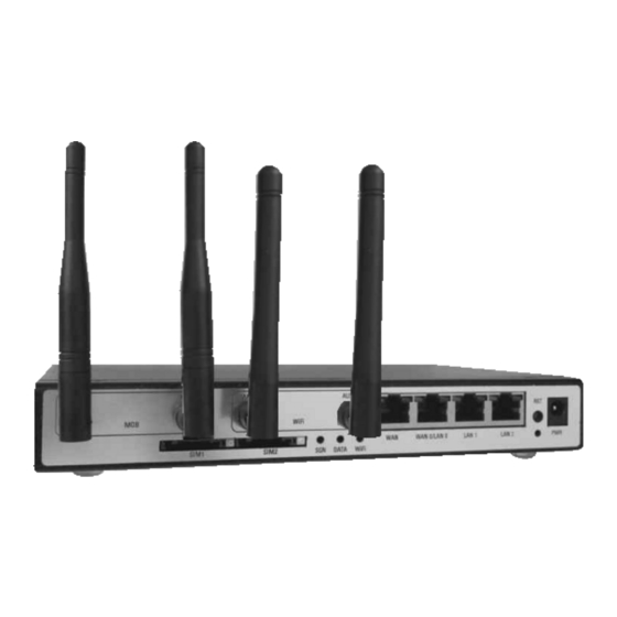
Bytton ICR features several external connectors and indicators, as described next.. Figure 4-6: Image of indicators and Connectors of Bytton ICR with one serial interface The concrete appearance depends upon the current equipping of the Bytton LTE, for instance you may have:... - Page 31 Towards the right edge, the round connector for the power supply jack, (labeled PWR) (12V Antenna Diversity Variants The versions of Bytton LTE equipment for antenna diversity or MIMO (multiple input/output) feature two antenna connectors (labeled MAIN and respectively AUX) for the Mobile network and / or for the Wi-Fi access point.
-
Page 32: Connecting The Data Cables
TOPEX Bytton (HSPA+ / LTE) 4.4. Connecting the data cables To ensure a proper functioning of the Bytton ICR unit, you must make the right cable connections, as described below. Figure 4-8: Connecting all the cables and accessories to Bytton For local network connection: Use standard UTP network cables (CUT 5) fitted with RJ45 connectors at both ends. - Page 33 100Base-T connection, and both types of Ethernet connections maybe used on the same time. The network cables are to be inserted with one end into the RJ-45 sockets of the Bytton LTE equipment labeled LAN1 or LAN2, also LAN0 when it is configured as local port.
-
Page 34: Figure 4-10: Connecting The Wan Cable
For WAN connection: Plug one end of the cable into the RJ45 port labeled “WAN” on the front panel of the Bytton LTE device and the other end into the Ethernet port of the DSL, Cable modem or other equipment that achieves a connection to the external network. - Page 35 Web interface if the serial link is RS-232 or EIA-485, this is established at the factory! Type of serial link When you order the Bytton LTE equipment with serial interfaces, you must specify, whether the serial interface shall be RS-232 or RS-485. The selection is done in the manufacturing process, the type cannot be changed via Web interface for configuration or by means of jumpers.
-
Page 36: Figure 4-11: Connecting The Serial Cables To Bytton Lte
Figure 4-11: Connecting the serial cables to Bytton LTE For power supply: To power the Bytton LTE unit, just insert the jack of the power supply adapter into the supply connector. Do not yet plug the adapter into the 230V mains outlet on the wall. -
Page 37: Configuring And Installing The Sim Card (S)
Your Bytton equipment may feature a single slot of two slots (dual SIM version) for SIM cards. In order for the Bytton LTE router to work, it must have at least one valid SIM card with subscription to the GSM/GPRS/EDGE, UMTS/HSPA or LTE mobile data carrier where you want to connect to. -
Page 38: Figure 4-13: Location Of The One Or Two Slots For Sim Cards
TOPEX Bytton (HSPA+ / LTE) The slots for SIM card are located on the front panel (the one with the indicators and connectors), to the left of the one or two MOB antennas, towards the bottom (under the SER connectors, if these are present). In case of dual-SIM equipments, the two slots for SIM trays are side by side, as shown in the illustration. - Page 39 TOPEX Bytton (HSPA+ / LTE) For inserting the SIM card(s) follow the next steps: 1. Push the little yellow button to eject the SIM carrier. 2. Pull out the holder (tray) for the SIM card. 3. Insert the SIM card into the holder, with the cut (notched) corner...
-
Page 40: Connecting The External Antennas
Figure 4-14: Illustration of the four steps sequence of inserting the SIM card into Bytton LTE. This procedure must also be followed when you replace the SIM card of the Bytton LTE equipment. 4.6. Connecting the external antennas To ensure a good quality of transmission and reduce radio interference, always use the antennas shipped in the Bytton ICR package. -
Page 41: Figure 4-15: Inserting The Connector Of The Gsm/3G Mobile Antenna
If only the Main antenna is connected, diversity will not operate the performances will be lower, but if you connect only the Aux antenna, the system may not work at all! Figure 4-17: Bytton LTE with four antenna connectors, two for LTE (4G Mobile) and two for N-type WiFi access point. -
Page 42: Figure 4-17: Attachment Of A Single Wifi Stick Antenna
The antennas for the WiFi Access Point of Bytton ICR are stick-type, with an articulation near the connector. In case of Bytton LTE units equipped with WiFi b/g module, a single WiFi stick antenna must be inserted. Use the sleeve of the 90 degree bent to thread the stick antenna into the circular male connector on the front panel (marked “WiFi),... -
Page 43: Power Up
Notice: The Bytton LTE unit and its antennas should be placed such as to be as far as possible from appliances or office equipment that is sensitive to radio interference (microwave ovens, copiers, TV sets, PC displays, and multimedia systems). -
Page 44: Status Indicators
SIM, at startup the indicator will blink, since the equipment tries to register to the mobile network, but then it will turn off, when the equipment finds out that registration is not possible. Note: In case of Bytton LTE devices that are not equipped with Mobile modules, the SGN led will be also missing! DATA –... -
Page 45: Configuration
Using the web browser, the configuration can be performed remotely: the desktop PC or notebook may be connected to the Bytton LTE Router either directly or through a switch by means of the wired (Ethernet) connection. Prior to using this Bytton LTE equipment you should check the basic settings to guarantee it will work in your environment (for instance, it may be required to change the default IP address). -
Page 46: Figure 5-2: Go To "Network And Internet" To Create A Network Connection For Bytton Lte
TOPEX Bytton (HSPA+ / LTE) Figure 5-2: Go to “Network and Internet” to create a network connection for Bytton LTE. Page: 46 / 290 ByttonLTE(full)_genericUsermanual_sw306FAS_revN.1.docx... -
Page 47: Automatic Ip Address
5.1.2 Automatic IP Address The simplest way is to set your network adapter to get its IP address automatically from Bytton LTE. The Rohde & Schwarz Topex S.A. mobile router features a DHCP server, so it can provide your PC with the correct IP address, DNS and Gateway. -
Page 48: Manual Ip Settings
Bytton LTE equipment! You should enter the IP address of the Bytton LTE device (by default 192.168.1.1) in the list of exceptions for the Proxy server: “Do not use proxy server for addresses beginning with …”... -
Page 49: First Connection
Figure 5-6: Enter the default IP address of the Web page into your browser. If you cannot connect to the Bytton LTE router because of problems in the settings of the IP address, you must go back to the factory default settings. Press the “RESET” button for at least three seconds. -
Page 50: Figure 5-9: Warning About The Certificate Of A Trusted Website
Figure 5-9: Warning about the certificate of a trusted website. You should click „Yes”, „OK” or „Accept” to go on. Type “OK” to accept the certificate for the Bytton LTE website. Other “Security Error” messages may warn you about “Domain Name Mismatch”, referring to the security certificate. -
Page 51: Log-In To Bytton Lte
Click the link of interest to you! Figure 5-11: Connecting to the configuration Web page of Bytton LTE. Now you will be asked to enter a user name and a password to access the configuration page of Rohde & Schwarz Topex S.A. Bytton LTE equipment. -
Page 52: Multiple Log-In To The Web-Interface Of Bytton
TOPEX Bytton (HSPA+ / LTE) 5.1.7 Multiple Log-in to the Web-interface of Bytton Generally, a complex system has several log-in types: different username and passwords, allowing correspondingly more or les management rights. These various users are allowed access to different sets of configurable parameters. -
Page 53: Figure 5-15B: Log-In As "Superuser
Figure 5-15b: Log-in as “superuser”. Following successful log-in as “superuser”, the corresponding main page Menu for the Rohde & Schwarz Topex S.A. Bytton LTE router should be shown on screen:. As can be seen, the “superuser” has access to at least one additional item of Menu, in this case than last menu element, called “Stuff”, which holds... - Page 54 Save button at the bottom of the screen to save it in the current page: Finally use the Commit button at the bottom of the Menu, to make these changes permanent after the restarting of the Bytton LTE equipment: Page: 54 / 290 ByttonLTE(full)_genericUsermanual_sw306FAS_revN.1.docx...
-
Page 55: Menu Items
TOPEX Bytton (HSPA+ / LTE) 5.1.8 MENU Items There are several sections (Menu items) on the configuration page of Bytton LTE device, as shown in the images below. Defending upon the type of authorization, you may have access to all the features, or only to some of them: Figure 5-16a: Web configuration page, listing sub-menu items for “admin”. -
Page 56: Figure 5-16B: Web Configuration Page, Listing All Sub-Menu Items For "Superuser
So for these sub-pages the menu elements remain the same, no matter how you log-in to the Web configuration interface of Bytton LTE. Figure 5-16b: Web configuration page, listing all sub-menu items for “superuser”. Page: 56 / 290... - Page 57 9. VOICE: In case of equipments that have voice capabilities (FXS telephone interface), this page shows info and allows you to modify parameters for the voice calls performed via Bytton LTE 10. Stuff: advanced “stuff”, such as status reporting via email, self-configuration by importing a .cfg file from a specified address, and bandwidth testing by timing file transfers.
- Page 58 To make these new parameter permanent, i.e. available even after restarting or resetting the equipment, you need to use the Commit button located at the bottom of the Menu list. This will save the new settings into the permanent memory of the Bytton LTE router. Additional menu items available for Superuser: As you can see, the sub-pages are the same, but several of them now include more items than in case of logging-in as Admin.
-
Page 59: Lan
Figure 5-18: LAN configuration page, IP Settings Settings for the IP LAN address of the Bytton LTE 3G+ router are the standard ones: IP Address and Netmask. These settings control how the Rohde & Schwarz Topex S.A. equipment connects into your local wired (Ethernet) computer network. -
Page 60: Figure 5-19: Changing The Default Ip Address Of Bytton On The Lan - Several Examples
“IP Aliasing” refers to the possibility of setting up multiple network addresses on the same low-level network device driver, in this case multiple IP addresses for the Ethernet or PPP interfaces of Bytton LTE. Use the blue link to go to the configuration page for the alternate IP addresses and net mask: At fist, the table with additional IP’s... - Page 61 TOPEX Bytton (HSPA+ / LTE) Note that in this case also the “Interface” drop list will show, besides the usual physical interfaces: BR0, WAN, Embedded Modem, WiFi station (when WiFi is set to Station and Ad Hoc instead of access point) , it will show also as options the logical interfaces: bridges, Virtual LANs, GRE, IPSEC or OPEN VPN tunnels, and so on: Use individual Save buttons to the right to save the settings for each supplementary IP addresses, then...
- Page 62 TOPEX Bytton (HSPA+ / LTE) Examples: When Bytton has a single IP in the local network and a fixed IP for the Ethernet WAN, the Interfaces will And the corresponding routing table is very simple: After you set the additional IP’s over the available interfaces of Bytton: Page: 62 / 290 ByttonLTE(full)_genericUsermanual_sw306FAS_revN.1.docx...
- Page 63 TOPEX Bytton (HSPA+ / LTE) The Iface status changes accordingly: Link encap:Ethernet HWaddr 00:19:70:49:F3:D7 inet addr:10.0.0.1 Bcast:10.0.0.255 Mask:255.255.255.0 UP BROADCAST RUNNING MULTICAST MTU:1500 Metric:1 RX packets:309 errors:0 dropped:0 overruns:0 frame:0 TX packets:403 errors:0 dropped:0 overruns:0 carrier:0 collisions:0 txqueuelen:0 RX bytes:35375 (34.5 KiB) TX bytes:114640 (111.9 KiB) br0:0 Link encap:Ethernet...
-
Page 64: Figure 5-21: Lan Configuration Page, Access The Link Loopback
TOPEX Bytton (HSPA+ / LTE) Base address:0x3000 wlan0 Link encap:Ethernet HWaddr 00:19:70:49:F3:D7 UP BROADCAST RUNNING MULTICAST MTU:1500 Metric:1 RX packets:0 errors:0 dropped:0 overruns:0 frame:0 TX packets:135 errors:0 dropped:0 overruns:0 carrier:0 collisions:0 txqueuelen:1000 RX bytes:0 (0.0 B) TX bytes:13640 (13.3 KiB) The respective additional addresses show up also in the Routing Table of Bytton: Kernel IP routing table Destination... -
Page 65: Software Configuration Of The Eth Switch
This is a feature of LAN>IP settings, but it allows versatile, detailed configuration, thus it is described in a full sub-chapter. The four-port switch/router of Bytton LTE is fully configurable via software, through the Web interface. You can leave three ETH ports in the LAN switch, or set configuration for each one. - Page 66 TOPEX Bytton (HSPA+ / LTE) to enter the configuration sub-page for the dual-port ETH switch of Bytton, as shown here: When left to the default SW (switch) option, as shown above, both ETH ports are in a hardware switch and thus share the same IP. By default, the third ETH port also in this switch.
- Page 67 TOPEX Bytton (HSPA+ / LTE) The Bridge Status indication changes accordingly: Also, you can see now that the default bridge br0, joins together, besides wlan0, three wired ETH ports, lan0, lan1 and lan2, which after being individually configured, are now distinct ports, as shown: This arrangement shows up also in Iface status: Link encap:Ethernet HWaddr 00:19:70:49:F3:D7...
- Page 68 TOPEX Bytton (HSPA+ / LTE) UP BROADCAST RUNNING MULTICAST MTU:1500 Metric:1 RX packets:70 errors:0 dropped:0 overruns:0 frame:0 TX packets:0 errors:0 dropped:0 overruns:0 carrier:0 collisions:0 txqueuelen:1000 RX bytes:6113 (5.9 KiB) TX bytes:0 (0.0 B) Link encap:Ethernet HWaddr 00:50:C2:F5:23:29 inet addr:192.168.1.148 Bcast:192.168.255.255 Mask:255.255.0.0 UP BROADCAST RUNNING MULTICAST MTU:1500...
- Page 69 TOPEX Bytton (HSPA+ / LTE) collisions:0 txqueuelen:1000 RX bytes:0 (0.0 B) TX bytes:46 (46.0 B) Base address:0x2000 lan1 Link encap:Ethernet HWaddr 00:50:C2:F5:23:2A inet addr:172.168.1.13 Bcast:172.168.1.15 Mask:255.255.255.252 UP BROADCAST RUNNING MULTICAST MTU:1500 Metric:1 RX packets:0 errors:0 dropped:0 overruns:0 frame:0 TX packets:0 errors:0 dropped:0 overruns:0 carrier:0 collisions:0 txqueuelen:0 RX bytes:0 (0.0 B) TX bytes:0 (0.0 B)
- Page 70 TOPEX Bytton (HSPA+ / LTE) Thus, when you leave it to the default “LAN0”, the port labeled LAN0/WAN0 (eth0) will remain bridged in the LAN switch, together with the other two interfaces that are unconditionally for LAN: The bridge also includes the WiFi embedded access point (wlan0). But, should you set it to WAN0 instead of the default LAN0, without IP, it will be taken out of the LAN switch and act as a secondary WAN port, with or (as in this...
- Page 71 TOPEX Bytton (HSPA+ / LTE) RX bytes:0 (0.0 B) TX bytes:44758 (43.7 KiB) lan2 Link encap:Ethernet HWaddr 00:50:C2:F5:23:2A inet addr:172.168.1.15 Bcast:172.168.255.255 Mask:255.255.255.254 UP BROADCAST RUNNING MULTICAST MTU:1500 Metric:1 RX packets:0 errors:0 dropped:0 overruns:0 frame:0 TX packets:547 errors:0 dropped:0 overruns:0 carrier:0 collisions:0 txqueuelen:0 RX bytes:0 (0.0 B) TX bytes:44758 (43.7 KiB)
- Page 72 Suppose you set up “192.168.148.148” as alternate IP address over the WAN interface: Following a Commit command and restart, the Bytton LTE equipment will be now accessible on the WAN side, through its port labeled “WAN0/LAN”, at the address for second WAN that was set previously: Page: 72 / 290 ByttonLTE(full)_genericUsermanual_sw306FAS_revN.1.docx...
- Page 73 TOPEX Bytton (HSPA+ / LTE) It also does answer to PING command in the 192.168.xxx.yyy network where Bytton LTE is now connected via its WAN0 interface: Page: 73 / 290 ByttonLTE(full)_genericUsermanual_sw306FAS_revN.1.docx...
-
Page 74: Using "Sw (Lan1, Lan2)" To Disable Two Local Ports
By default, they are joined together in a switch, but you can take LAN1 and LAN2 out of this switch and assign them individual IP addresses and subnet masks. A powerful application of this technique is software disabling of two of the Ethernet ports of Bytton LTE, as described below. - Page 75 TOPEX Bytton (HSPA+ / LTE) Save this settings with Save then use Commit to make the changes permanent. Following a reboot, the Bytton equipment starts operating with the new parameters, and now LAN1 and LAN2, although physically active, are disabled from software. When you connect a cable to them, nothing happens! The browsers will show you error messages such as: The green LED in the connector lights up, and the yellow LED is permanently ON, it does not blink to indicate data traffic –...
- Page 76 TOPEX Bytton (HSPA+ / LTE) Also, the operating system command “ipconfig” will show the respective Ethernet port as being “unoperational”: The Windows Network Diagnostic tool will try to troubleshoot the unresponsive Ethernet port, but will give Now only the port LAN0 is active for the local network. This can be seen very well in “Bridge Status”, where only the interface “lan0”...
- Page 77 TOPEX Bytton (HSPA+ / LTE) Explanations: Link encap:Ethernet HWaddr 00:19:70:49:F3:D7 inet addr:172.168.1.1 Bcast:172.168.1.255 Mask:255.255.255.0 UP BROADCAST RUNNING MULTICAST MTU:1500 Metric:1 RX packets:11348 errors:0 dropped:0 overruns:0 frame:0 TX packets:14116 errors:0 dropped:0 overruns:0 carrier:0 collisions:0 txqueuelen:0 RX bytes:3559084 (3.3 MiB) TX bytes:13263482 (12.6 MiB) Link encap:Ethernet HWaddr 00:50:C2:F5:23:2A UP BROADCAST RUNNING MULTICAST...
- Page 78 TOPEX Bytton (HSPA+ / LTE) UP BROADCAST RUNNING MULTICAST MTU:1500 Metric:1 RX packets:0 errors:0 dropped:0 overruns:0 frame:0 TX packets:0 errors:0 dropped:0 overruns:0 carrier:0 collisions:0 txqueuelen:0 RX bytes:0 (0.0 B) TX bytes:0 (0.0 B) Link encap:Ethernet HWaddr 00:50:C2:F5:23:29 inet addr:192.168.1.148 Bcast:192.168.1.255 Mask:255.255.255.0 UP BROADCAST RUNNING MULTICAST MTU:1500...
-
Page 79: Commit
Warning! While committing changes, when resetting Bytton LTE or while loading a new program image, the equipment will cease operation for a few seconds. This means all connections: data link, WiFi, serial, LAN and WAN will be interrupted, then will resume when Bytton LTE starts again. -
Page 80: Dhcp Settings
Forward to means the local requests for DHCP will be handled by a remote server, instead of Bytton. Warning: If you enable the DHCP feature of Bytton LTE, make sure that there is no other DHCP server in your local network! Start IP: Starting IP Address. -
Page 81: Figure 5-25: Open Network And Sharing Center To Verify The Assignment Of Ip Addresses
You can also verify that the default gateway is 192.168.1.1 (the Bytton LTE device) and the Subnet Mask is 255.255.255.0. Figure 5-27: The Details tab of the connection to Bytton LTE shows its IP address. Forward to Page: 81 / 290 ByttonLTE(full)_genericUsermanual_sw306FAS_revN.1.docx... -
Page 82: Figure 5-28: Using The "Forward To" Option For Dhcp Server In Lan Configuration Webpage
TOPEX Bytton (HSPA+ / LTE) You may select the third option, “Forward to”, to pass the DHCP requests to a remote server, instead of the local Bytton LTE equipment. In this case, you must complete the IP address of that server, such as 192.168.144.88 in this example, and select the interface (IF) over... -
Page 83: Figure 5-31: Click The Link "Filter List Mac" To Use This Feature
TOPEX Bytton (HSPA+ / LTE) As can be seen from the examples above, the servers for DNS may be either in the local network or over the Internet or WAN. Filter List MAC Click the first blue link located at the bottom to reach this feature. It is an additional security feature, for the whole Bytton ICR equipment. -
Page 84: Figure 5-34: Defining Mac Entries In The Table "Filter List Mac
TOPEX Bytton (HSPA+ / LTE) To activate it, fist, select either Allow, or Deny, then define the addresses which will be permitted, respectively rejected. You can add as many records as you like in this table, but bear in mind that the rule you choose (either Accept them or Deny these MACs) will apply for al physical addresses and IP addresses in the list! Figure 5-34: Defining MAC entries in the table “Filter List MAC”. - Page 85 TOPEX Bytton (HSPA+ / LTE) Example of usage for “Filter List MAC”: 1. First, identify the MAC of the device that you want to connect to the bytton ICR equipement, such as the ntework card of the PC computer in this case: 2.
- Page 86 2.The MAC Security for WiFi lets you specify up to five physical addresses whose access will be selective allowed or denied. But the respective feature applied only to the wireless clients connected to Bytton LTE, while Filter List MAC described previously applies to all local connections, no matter if they are cabled Ethernet or WiFi! 3.The MAC filtering feature does not guarantee a high level of security, since the hardware...
-
Page 87: Figure 5-35: Defining Mac Entries In The Table "Filter List Mac
TOPEX Bytton (HSPA+ / LTE) This feature allows you to set up additional DHC services, over different interfaces of Bytton. You may choose the interface form the drop list, then set up start addresses, and finally the lease time, for each of these interfaces, as shown Figure 5-35: Defining MAC entries in the table “Filter List MAC”. -
Page 88: Wifi Settings
TOPEX Bytton (HSPA+ / LTE) 5.2.6 WiFi Settings Here you can establish the settings for the embedded wireless Access Point (802.11b/g base station) of the Bytton LTE router: Figure 5-37: The LAN page for WiFi Settings. Note: The MAC addresses set from this page, are the unique MAC assigned to the network interfaces of the client devices connected to Bytton router. - Page 89 APs. Connection Mode: It has two options, Infrastructure and Ad-Hoc. Infrastructure: default operation mode. Several Wi-Fi clients can connect to the Bytton LTE equipment, which is acting as server. The “Infrastructure” mode takes full advantage of the AP's ability to cover wide areas.
- Page 90 Bytton, while previously in was included in the BR0 default local bridge! Connections to WiFi AP’s In the System Log of Bytton LTE you o can see these connections: Jul 13 13:06:30 bytton user.notice root: LOG guestwifi Jul 13 13:05:50 bytton user.info kernel: br0: port 2(wlan0) entering learning state Jul 13 13:06:01 bytton cron.err crond[1640]: USER root pid 5330 cmd net_moni...
-
Page 91: Figure 5-35: Select The Radio Channels Of The Wifi Access Point
TOPEX Bytton (HSPA+ / LTE) Jul 13 13:10:59 bytton user.notice root: LOG Productie Jul 13 13:11:00 bytton user.notice root: CONNECT ON WIFI AP: Productie Jul 13 13:11:01 bytton cron.err crond[1640]: USER root pid 6038 cmd net_moni ………………………………………………………………………… Also, in ROUTING>Routes you can see now the route for the wlan local wireless interface: Kernel IP routing table Destination Gateway... -
Page 92: Figure 5-38: Select And Set Up The Wep Security Features
TOPEX Bytton (HSPA+ / LTE) WEP Security: Enables or disables WEP (Wired Equivalent Privacy) encryption. WEP encryption is used to protect data transmitted from one end point to another. The encryption level (64-bit or 128-bit) is given by the length of the WEP Key you enter. -
Page 93: Figure 5-40: Enable And Configure Mac Security For Wifi
TOPEX Bytton (HSPA+ / LTE) MAC Security Controls access to the Wi-Fi network based upon MACs (physical addresses of the client devices) By default MAC Security is Disabled, allowing any wireless client to connect, without checking its MAC- address. You can enter up to five MAC addresses to be filtered by this kind of physical ID security. -
Page 94: 802.1X" Settings
TOPEX Bytton (HSPA+ / LTE) 5.2.7 “802.1x” Settings This page controls settings related to the configuration for EAPOL, according to the standard 802.1X- 2004 (Specification IEEE 802.1X-2004). By default, it is Disabled: Figure 5-41: 802.1x Settings, by default Disabled. When you need to use 802.1x authentication, you must Enable and configure this feature, as shown: Enabled 802.1X WEP/WPA... -
Page 95: Figure 5-42: Enable And Configure Settings For 802.1X Eapol
TOPEX Bytton (HSPA+ / LTE) Figure 5-42: Enable and configure settings for 802.1x EAPOL. After you have enabled this feature, it will control authentication on the LAN side, allowing access only to the clients which are acknowledged by a Radius server. For details, please see the embedded help page: ##### IEEE 802.1X-2004 related configuration # Require IEEE 802.1X authorization... -
Page 96: Figure 5-43: Embedded Help For The Parameters Of 802.1X Authentication For Eapol
TOPEX Bytton (HSPA+ / LTE) # version 2. However, there are many client implementations that do not handle # the new version number correctly (they seem to drop the frames completely). #eapol_version=2 # Optional displayable message sent with EAP Request-Identity. The first \0 # in this string will be converted to ASCII-0 (nul). -
Page 97: Bridge
Ethernet interface with an OpenVPN-driven TAP interface at two separate locations, it is possible to logically merge both Ethernet networks, as if they were a single Ethernet subnet. The Bridge feature of Bytton LTE consist of a table (by default empty) and several useful links beneath it. Page: 97 / 290... -
Page 98: Figure 5-45: Edit An Entry In The "Bridge" Table
TOPEX Bytton (HSPA+ / LTE) These clickable links include: - Bridge Help, - displaying the State of the bridges defined, - displaying advanced info about all the Interfaces of the equipment: To create new bridge, use Add New, then Edit: Figure 5-45: Edit an entry in the “Bridge”... -
Page 99: Figure 5-46: Several Entries In The "Bridge" Table
TOPEX Bytton (HSPA+ / LTE) You can define as many bridges as you need:: Figure 5-46: Several entries in the “Bridge” table. Once you define a bridge (br1, br2, br3 in these examples), they show up in Bridge Status: Figure 5-47: Bridges showing up in “Bridge Status”. And also the program automatically inserts the corresponding routes for them: Figure 5-48: The same bridges in the “Routes”... -
Page 100: Figure 5-49: Details Of Bridges In The "Bridge Status" Table
TOPEX Bytton (HSPA+ / LTE) Bridge Status: You can check the state of the three bridges created above by the link “BR Status: Figure 5-49: Details of bridges in the “Bridge Status” table. Each bridge has an unique ID hex numbe, such as “8000.00197049f3d”7. This number shows up when the bridge is in effect, that means after you issued a “Commit”. -
Page 101: Interface Status" And "Test Net" Features
Interface Status: This link is present at the bottom of several of the LAN configuration pages of the Web interface for Bytton LTE, as shown: etc. Figure 5-50: The window “Interface Status” and the corresponding link present in several configuration pages. - Page 102 TOPEX Bytton (HSPA+ / LTE) RX packets:0 errors:0 dropped:0 overruns:0 frame:0 TX packets:1 errors:0 dropped:0 overruns:0 carrier:0 collisions:0 txqueuelen:1000 RX bytes:0 (0.0 B) TX bytes:46 (46.0 B) Base address:0x2000 Link encap:Local Loopback inet addr:127.0.0.1 Mask:255.0.0.0 UP LOOPBACK RUNNING MTU:16436 Metric:1 RX packets:530 errors:0 dropped:0 overruns:0 frame:0 TX packets:530 errors:0 dropped:0 overruns:0 carrier:0 collisions:0 txqueuelen:0...
- Page 103 Since it is a loopback interface, the number of bytes sent out will always be identical to the number of bytes received. A few commented examples will show how Iface Status may be used to find out what is going on over the interfaces of Bytton LTE: Link encap:Ethernet HWaddr 00:19:70:49:F3:D7 inet addr:10.0.0.1...
- Page 104 TOPEX Bytton (HSPA+ / LTE) When the connection is achieved via 3G/4G mobile network instead or cabled Ethernet, Iface Status reflects the changes – data comes in via ppp1 and gets out through lan. The wan traffic is nil, while the WiFi interface wlan0 is active, but not used for data transfers: Link encap:Ethernet HWaddr 00:19:70:49:F3:D7...
- Page 105 TOPEX Bytton (HSPA+ / LTE) collisions:0 txqueuelen:0 RX bytes:3467166 (3.3 MiB) TX bytes:0 (0.0 B) Link encap:Ethernet HWaddr 00:50:C2:F5:23:2A UP BROADCAST RUNNING MULTICAST MTU:1500 Metric:1 RX packets:160518 errors:3 dropped:0 overruns:0 frame:0 TX packets:298568 errors:1 dropped:0 overruns:0 carrier:0 collisions:0 txqueuelen:1000 RX bytes:14025308 (13.3 MiB) TX bytes:412045038 (392.9 MiB) Base address:0x2200 lan0...
- Page 106 TOPEX Bytton (HSPA+ / LTE) Base address:0x2200 lan0.4 Link encap:Ethernet HWaddr 00:50:C2:F5:23:27 inet addr:192.168.148.255 Bcast:192.168.148.255 Mask:255.255.255.0 UP BROADCAST RUNNING MULTICAST MTU:1500 Metric:1 RX packets:0 errors:0 dropped:0 overruns:0 frame:0 TX packets:0 errors:0 dropped:0 overruns:0 carrier:0 collisions:0 txqueuelen:0 RX bytes:0 (0.0 B) TX bytes:0 (0.0 B) lan0:2 Link encap:Ethernet...
- Page 107 TOPEX Bytton (HSPA+ / LTE) No LAN in the default bridge! When the LAN1 and LAN2 Ethernet ports are removed from the default Ethernet switch, as shown here: and instead assigned independent IP addresses, in different address ranges : the default bridge, br0, contains now only the WiFi interface, wlan0, since the four ETH ports are now all individually assigned : bridge name bridge id STP enabled...
- Page 108 0.0.0.0 0 ppp1 From now on, the newly created LAN1 and LAN2 ports will be displayed as options in the “Interfaces” drop list which shows up in several configuration menus of the Bytton LTE equipment: Page: 108 / 290 ByttonLTE(full)_genericUsermanual_sw306FAS_revN.1.docx...
-
Page 109: Figure 5-51: The Link "Test Net" At The Bottom Of The "Interface Status" Page
At the bottom of the “ Interface Status” subpage, there is another clickable link called “Test_Net”. This is used to open a window that allows testing of the network where Bytton LTE is connected: Figure 5-51: The link “Test Net” at the bottom of the “Interface Status” page. - Page 110 TOPEX Bytton (HSPA+ / LTE) Network test You can issue PING commands to different addresses, trace the route to a specified IP, or send other network commands. The results are always shown in the upper pane, called “Test”: For instance, you may PING different destination IP addresses (the default 127.0.0.1 is the loopback), specifying the number of...
- Page 111 TOPEX Bytton (HSPA+ / LTE) PING 127.0.0.1 (127.0.0.1): 455 data bytes 463 bytes from 127.0.0.1: seq=0 ttl=64 time=0.556 ms 463 bytes from 127.0.0.1: seq=1 ttl=64 time=0.413 ms 463 bytes from 127.0.0.1: seq=2 ttl=64 time=0.404 ms 463 bytes from 127.0.0.1: seq=3 ttl=64 time=0.402 ms --- 127.0.0.1 ping statistics --- 4 packets transmitted, 4 packets received, 0% packet loss round-trip min/avg/max = 0.402/0.443/0.556 ms...
- Page 112 TOPEX Bytton (HSPA+ / LTE) Other network debugging tools are also available in the “Test Net” utility page. TRACE For instance, the “Trace IP/NS” box allows you to trace the route towards the respective IP address and also looks up for addresses of nameservers used along this route.
- Page 113 TOPEX Bytton (HSPA+ / LTE) ewro-crli1.qrli2.buh.ew.ro (81.24.28.198) 1247.112 ms 1271.456 ms 1306.368 ms ip4-81-24-28-213.euroweb.ro (81.24.28.213) 1355.474 ms 1139.117 ms 1139.388 ms webhosting.euroweb.ro (193.226.61.45) 1259.150 ms 1250.796 ms 1119.130 And respectively: traceroute to k.ro (194.102.255.23), 30 hops max, 38 byte packets * * * 172.20.175.201 (172.20.175.201) 2332.538 ms...
-
Page 114: Figure 5-54: Commands Available In "Network Tests" Page
BusyBox is designed to minimize size and to work with limited resources, thus is well fitted for embedded operating systems such as Bytton LTE. See below a few examples: Linux bytton 2.6.34 #66 Tue Jun 12 17:31:38 EEST 2012 ppc unknown... -
Page 115: Vlan
TOPEX Bytton (HSPA+ / LTE) 5.2.10 VLAN This page configure the settings for the Virtual LANs of Bytton LTE. Figure 5-55: The “VLAN” page with several virtual LANs defined. A virtual or logical LAN is a subgroup in the physical local area network, which is created by software. - Page 116 TOPEX Bytton (HSPA+ / LTE) At first the table is empty, you must use Add New to create additional entry, then Edit change parameters. Also, each VLAN definition that you have entered may be individually saved or deleted, using the links to the right of the table. As you can see, when you set up the Interface to be used for each VLAN, the drop list shows not only the three physical interfaces: - BR0 (Eth ports for LAN and WiFi clients...
- Page 117 TOPEX Bytton (HSPA+ / LTE) Why use VLANs? - to minimize the broadcast domain. Broadcasts are required for the normal function of a network. Many protocols and applications depend on broadcast communication to function properly. But certain network devices will send out large amounts of broadcast traffic that can really slow down the network, especially when it reaches a certain size, usually 600 devices or more.
- Page 118 TOPEX Bytton (HSPA+ / LTE) Using VLANs: After defining the VLANs in the table, such as this: then issuing a Commit command to make the changes permanent, the VLAN interfaces will be visible in Interface Status: br0.19 Link encap:Ethernet HWaddr 00:50:C2:F5:23:2A inet addr:109.166.184.149 Bcast:109.255.255.255 Mask:255.0.0.0...
- Page 119 HWaddr 00:50:C2:F5:23:29 inet addr:192.168.148.4 Bcast:192.168.148.255 Mask:255.255.255.0 UP BROADCAST RUNNING MULTICAST MTU:1500 Metric:1 Base address:0x3000 The corresponding routes have been added in the static Routing Table of Bytton LTE: Kernel IP routing table Destination Gateway Genmask Flags Metric Ref Use Iface 10.64.64.65 0.0.0.0...
-
Page 120: Eth Ports
TOPEX Bytton (HSPA+ / LTE) 5.2.11 ETH Ports This menu element allow for fine tuning (monitoring and control) of each ETH ports of the Bytton equipment: Figure 5-56: The “ETH ports” page for physical configuration of Ethernet ports. While previous “IP settings”, including LAN0/WAN0 and individual IP and netmask assignment for each port referred to the logical aspects, this configuration page refers to the physical parameters for each Ethernet port of the equipment! ETH Ports:... - Page 121 Ethernet adapters to exchange automatically information over a link, about speed and duplex abilities. By default, the ETH ports of Bytton LTE are set to auto-negotiation, since different users may connect to it, having several types of network adapters. The users may have either a 10 Mb, a 100 Mb Ethernet, or a 10/100 Mb card in their notebooks, so the switch of Bytton must be able to negotiate their speed and duplex mode.
- Page 122 TOPEX Bytton (HSPA+ / LTE) In the example below, the wan port is with the default settings (auto negotiation, full duplex) and is active for a 100Mbps connection, while lan0 was set to half duplex, speed of 10 Mbps and is not in use (no link actually detected): After a reboot, the new parameters for operation of Eth ports will be active, and will show up in the “ETH Port”...
- Page 123 TOPEX Bytton (HSPA+ / LTE) When every ETH port is individually configured (LAN1 and LAN2 have been assigned each its own IP, LAN0 is set to second WAN, but not connected), all four Ethernet ports will show up accordingly in the Port Status display pane: STATUS wan Speed: 100Mb/s...
- Page 124 TOPEX Bytton (HSPA+ / LTE) The routing table will also show the routes for the local ETH ports whose IP addresses have been individually assigned: Kernel IP routing table Destination Gateway Genmask Flags Metric Ref Use Iface 193.57.235.84 192.168.1.8 255.255.255.255 UGH 0 wan 172.168.1.12 0.0.0.0...
- Page 125 172.168.1.13 00:06:4f:02:15:82 192.168.1.8 b4:99:ba:a9:37:5c 192.168.151.161 00:50:c2:e4:b0:c3 lan0 192.168.1.88 f4:ce:46:fb:b5:da 192.168.144.22 6c:f0:49:76:24:4b 192.168.149.5 6c:62:6d:ad:61:7b lan0 Other examples or ARP Table shown on Bytton LTE: IP address HW type Flags HW address Mask Device 172.27.168.7 00:00:00:00:00:00 lan0 10.0.0.13 00:06:4f:02:15:82 172.27.168.70 00:00:00:00:00:00 lan0...
-
Page 126: Figure 5-56: The "Arp Table" With Multiple Entries
TOPEX Bytton (HSPA+ / LTE) 192.168.1.8 b4:99:ba:a9:37:5c 172.27.168.7 00:00:00:00:00:00 lan0 Usage of ARP table All IP devices must have an ARP table. This ARP cache can be used for troubleshooting the network connectivity. When everything is working fine with ARP, you will have a dynamic ARP entry that is complete (both MAC and IP values are there). -
Page 127: Mtu
MTU can be set to is 68. Also, for network protocols other than TCP, different MTU sizes may apply. On your machine (PC computer or Bytton LTE) you must also set the MTU value in accordance with the specific settings of the data network you use. Ideally, you want the MTU to be the same as the smallest MTU of all the networks between your machine and a message's final destination. - Page 128 TOPEX Bytton (HSPA+ / LTE) You should always bear in mind that the MTU is the maximum physical value. Thus, in many instances the net payload (logical size) must be smaller. For example, when you use tunnels, they add up specific headers to the packets, so you must reduce the MTU to achieve an overall length no greater that 1500! The same holds true for PPP over Ethernet, you must take into account the extra encapsulation, the actual length must be smaller, in order not to exceed the 1500 bytes limit!
- Page 129 “1472” seems to be just right! The final result is that this is your best MTU value for the respective interface and provider. Bytton LTE lets you specify the optimal MTU value for each of the physical or logical interfaces of the equipment: The drop list lets you choose from all the available interfaces of the equipment: Select the corresponding MTU value, save the individual entry, then use the button “Save and Reload”...
- Page 130 TOPEX Bytton (HSPA+ / LTE) Note that the VLAN table also allows you to set the MTU value for each of the VLANs you create: The corresponding values set up for MTU over different interfaces can be seen in Iface Status: Link encap:Ethernet HWaddr 00:50:C2:F5:23:27 inet addr:10.0.58.39...
-
Page 131: Wan
TOPEX Bytton (HSPA+ / LTE) 5.3 WAN Here are the pages for configuring the WAN (remote network) side of the Bytton LTE router Figure 5-58: The WAN webpage. This WAN Home-page briefly describes your options in setting the WAN connection. - Page 132 TOPEX Bytton (HSPA+ / LTE) Primary Interface: You can select either: 11. Embedded modem (PPP link) 12. PPP over Ethernet (PPPoE) 13. Ethernet Port Secondary Interface: You can select either: 14. Embedded modem (PPP link) 15. PPP over Ethernet (PPPoE) 16.
- Page 133 When the Internet provider that you connect to performs the masquerading at its location, you do not need to do NAT anymore, you should leave this option Disabled. This is why the NAT table of Bytton LTE does allow selective masquerading, you can select to enable or not NAT for each of the interfaces: Page: 133 / 290 ByttonLTE(full)_genericUsermanual_sw306FAS_revN.1.docx...
- Page 134 TOPEX Bytton (HSPA+ / LTE) Save each individual entry, then use the button “Save and Reload” The Firewall of Bytton LTE will automatically generate the corresponding NAT rules, in the example below, for enabling masquerading over ppp1 and respectively wan interfaces: Page: 134 / 290 ByttonLTE(full)_genericUsermanual_sw306FAS_revN.1.docx...
-
Page 135: Figure 5-60: Example Of Setting Up Primary And Secondary Wan Interfaces, Using Failover
TOPEX Bytton (HSPA+ / LTE) Examples of Failover action: In your office you have a local network with cable or ADSL as WAN connection, which uses Bytton LTE as a backup link. You should set the Primary Interface to “Ethernet port” and the secondary one to the embedded mobile modem: Figure 5-60: Example of setting up primary and secondary WAN Interfaces, using Failover. -
Page 136: Wan Management
WAN is always enabled! As you can see in the following examples, the Web interface for configuring Bytton LTE is accessible both on the local side (addresses in range 10.0.0.xxx): And also on the WAN side (addresses in class 192.168.1.yyy): Page: 136 / 290 ByttonLTE(full)_genericUsermanual_sw306FAS_revN.1.docx... -
Page 137: Wan Port
TOPEX Bytton (HSPA+ / LTE) 5.3.3. WAN Port Whenever you use an Ethernet interface for WAN connection, you must fill in the settings “IP Settings for the WAN Ethernet Interface”. Figure 5-63: Webpage for setting up WAN Port in the WAN settings. Address Type: options are Static or DHCP Assigned. -
Page 138: Figure 5-65: Examples Of Setting Static Address For Wan Eth Interface In The Wan Pages
TOPEX Bytton (HSPA+ / LTE) Figure 5-65: Examples of setting Static address for WAN Eth interface in the WAN pages. Corresponding routing table for Static WAN address of 192.168.1.148 with 192.168.1.8 gateway: Kernel IP routing table Destination Gateway Genmask Flags Metric Ref Use Iface 10.0.0.0 0.0.0.0... -
Page 139: Figure 5-67: Settings For Ppp Over Ethernet Connection In Webpage For Wan
Redial Period: time in seconds until redialing a connection, if it was broken, such as 5 seconds. Idle Time: Bytton LTE can disable the connection when there is no more data traffic. If no data packet is sent through the interface for a specified period of time, the Internet connection will be broken. This is useful in case of connections where you pay per connected time. -
Page 140: Ppp
TOPEX Bytton (HSPA+ / LTE) At the data level, the equivalent of MTU is MSS (see further on in the manual), so you should also set this parameter accordingly. 5.3.5. PPP Settings for the PPP connections achieved via embedded radio modem. To ensure high versatility together with ease of use, this page has just settings for the APN, username and password, while several specialized configurations, which are less often used - for modem, for connection and for routing - are located on the “PPP Advanced Settings”... -
Page 141: Figure 5-69A: Settings For Ppp Link In Case Of Dual-Sim Bytton Equipment
The default is Disabled. Figure 5-69b: Settings for the second SIM of the PPP wireless link, in case of dual-SIM Bytton LTE device. Parameters for switching between SIM cards Check link interval: time interval that Bytton expects reply for the IP destination of the probe (the delay between successive pings, in second)s. - Page 142 If you set the time interval to 0 (zero), the dial-up connection will remain always on, even if there is no data traffic on the remote interface. When it detects outgoing data traffic, Bytton LTE automatically performs dial-up, in order to connect to the Internet.
-
Page 143: Ppp Advanced Settings
Point Protocol for the internal data terminal, in this case the embedded GSM/HSPA+ or LTE modem. Figure 5-70: Advanced PPP Settings for the embedded modem of Bytton LTE. You need to change these advanced settings when you go to a region with different settings, if you use a different network operator or when you replace the embedded HSPA modem with another, external 3G modem that requires special parameters. -
Page 144: Figure 5-71: Ppp Advanced Settings -Parameters For The Wireless Data Link
TOPEX Bytton (HSPA+ / LTE) There are five “AT Init Command” fields, if there is no need to use all of them, fill the remaining with “AT”. You should not leave empty fields in this section! AT Dial Command: Dial String, the AT command used to dial to the ISP, which includes the mobile phone number to be dialed. -
Page 145: Figure 5-72: Ppp Check Data Link Settings Bytton Lte
By default, this feature is disabled – its fields are colored in gray, to show that you cannot edit them. Figure 5-72: PPP Check Data Link settings Bytton LTE. First you must Enable it, then use Edit to perform changes of the way how Bytton LTE checks the data link and finally Save. -
Page 146: Figure 5-75: Example With Values Of Settings For The "Ppp Check Data Link" Feature
IP - remote IP address that Bytton will response at ping command. This must be a IP address that will either answer to the ping command issued by Bytton, or generate PING packets for Bytton LTE to listen SRC IP – The source IP for PING packets. You can send ping with a “source IP”. This can be LAN, Loopback or Tunnel IP. - Page 147 With the above settings, Bytton will send every hour (3600 seconds) a number of three ping packets to the remote IP address “74.125.87.106”, with IP source the IP of the SIM connection. When Bytton LTE does no longer receive a reply to the PING issued, it will restart (reset) the SIM data connection.
-
Page 148: Tunnels
These “Tunnels Configuration Pages” has several sections, according to the type of tunnels you want to use: GRE, IPSEC, PPTP, Open VNP and so on. Depending upon the actual firmware revision running on your Bytton LTE, the Tunnels web page may contain several types of tunnels, form three to six sub-pages. -
Page 149: Gre
5.4.1 GRE Settings for the GRE IP Tunnels, which is used when you need to perform IP tunneling in order to achieve a Virtual Private Network using several Bytton LTE devices interconnected over the 3G mobile communications network. Figure 5-78: Aspect of GRE section of the “TUNNELS” Web page. - Page 150 Depending upon the actual requirements of your application, you may use a single GRE tunnel, or several, with different parameters for each tunnel gret1, gret2, gret3 and so on. See the first two gre tunnels now present in the routing table of Bytton LTE: Kernel IP routing table...
-
Page 151: Ipsec
IP addresses; - between a gateway in the field (the Bytton LTE unit) and the remote network of the company. This kind of application is called “road warrior”, because the agent is on the road and he must connect safely to the company’s network over a public network such as the Internet.This kind of IPSEC tunnel is used to... -
Page 152: Figure 5-82: Global Ipsec Settings, On Top Of The Ipsec Configuration Table
"Interface" setting defined in each "Specific Tunnel Configuration". This means that when you define an individual GRE tunnel, the filed “Interface” will not be editable, it will show “Default Route”, since it is the same for all tunnels of Bytton LTE. Page: 152 / 290 ByttonLTE(full)_genericUsermanual_sw306FAS_revN.1.docx... -
Page 153: Figure 5-84: Specific Ipsec Settings
Now the field “Interface” shows a drop list, allowing you to choose for each tunnel one of the physical interfaces of the Bytton LTE equipment. Set up specific IPSEC Tunnel Settings: Here are set the parameters that are specific for each tunnel, which are located at the bottom of the page: Figure 5-84: Specific IPSEC settings. -
Page 154: Figure 5-85: Define Or Modify The Specific Ipsec Settings
TOPEX Bytton (HSPA+ / LTE) Figure 5-85: Define or modify the Specific IPSEC settings. Description - is an optional setting, it only helps identifying the tunnel. Interface - when global setting "Use default route interface for all tunnels" is set to yes, the specific interface won't be available for modification Max. -
Page 155: Figure 5-86: Using The Link "Configure Authentication Keys
TOPEX Bytton (HSPA+ / LTE) Authentication Method – Select either PSK, RSA or x.509 certificate. based on the authentication method chosen, the Authentication Keys will have to be configured accordingly. To configure the Authentication Keys go back to the IPSEC main page and select the link Configure Authentication Keys located towards the bottom: Figure 5-86: Using the link “Configure... -
Page 156: Figure 5-87: Ipsec Web Page For Managing Rsa And Psk Keys, And X.509 Certificates
TOPEX Bytton (HSPA+ / LTE) ESP Key Life – duration of validity of the ESP key, must be same value as on the remote party Dead Peer Detection Settings Dead Peer Detection is used to detect whether the peer is alive or not. When the peer is detected as dead, the IPSec and IKE Security Association are deleted. -
Page 157: Figure 5-88: Generate Local Rsa Key And Set Or Generate Remote Psk Key
TOPEX Bytton (HSPA+ / LTE) Generate the local keys or enter the remote keys: Figure 5-88: Generate local RSA key and set or generate remote PSK key. Configure PSK key: Page: 157 / 290 ByttonLTE(full)_genericUsermanual_sw306FAS_revN.1.docx... -
Page 158: Figure 5-98: Upload The Certificate Files For X.509
TOPEX Bytton (HSPA+ / LTE) Setting the X.509 Certificates: For secure connections, the web browsers use SSL authentication with "X.509" certificates. This "Digital Certificate Standard" was issued by ITU-T for the secure management and distribution of digitally signed certificates across secure Internet networks. The strong authentication goes beyond a simple password to verify user identity, using instead advanced credentials, which are created by cryptographic means. -
Page 159: Figure 5-90B: "Ipsec Status" For One Ip Sec Tunnel
TOPEX Bytton (HSPA+ / LTE) IP Sec Status will display this information Figure 5-90b: “IPSEC STATUS” for one IP Sec tunnel. 000 interface lo/lo ::1:500 000 interface lo/lo 127.0.0.1:500 000 interface wan/wan 192.168.144.29:500 000 interface br0/br0 192.168.1.1:500 000 interface br0:0/br0:0 192.168.1.195:500 000 %myid = (none) 000 debug none 000 "ipsec1": 122.168.1.0/24===192.168.143.34...192.168.143.32===192.169.100.0/24;... -
Page 160: Figure 5-90C: "Ipsec Status" For Three Ip Sec Tunnels
TOPEX Bytton (HSPA+ / LTE) Performance: uptime: 6 minutes, since Mar 22 16:20:36 2013 worker threads: 9 idle of 16, job queue load: 0, scheduled events: 0 loaded plugins: aes des sha1 sha2 md5 fips-prf random x509 pubkey xcbc hmac gmp kernel-netlink stroke Listening IP addresses: 192.168.144.29... -
Page 161: Pptp
VPN node to another over a public network such as the Internet. By default, it is disabled: Figure 5-91 Web configuration page for PPTP, disabled. Bytton LTE can be set up to operate as a Client for the PTP tunneling protocol. Figure 5-92: Setting up parameters as Client for PPTP. -
Page 162: Ovpn
TCP/UDP port over an unsecured network such as mobile Internet and thus establish VPNs. OVPN is simple, easy to set up and use, and still powerful. GRE and IPSec have been implemented previously, but now you can use OpenVPN too, on the Bytton LTE equipments! While other VPN solutions often use proprietary or non-standard mechanisms, OpenVPN has a modular concept, both for underlying security and for networking. -
Page 163: Figure 5-94: Configure The Parameters For Open Vpn
TOPEX Bytton (HSPA+ / LTE) OVPN can be configures either as TUN or TAP interface – TAP operates at layer 2 level and simulates Ethernet frames, while the Tunnel interface operates with layer 3 packets, like IP packets. Tap can be used to create a network bridge, while TAB is used with routing. -
Page 164: Figure 5-96: Edit The Certificate For Crt Client
TOPEX Bytton (HSPA+ / LTE) Then for CRT Client : Figure 5-96: Edit the certificate for CRT Client. Page: 164 / 290 ByttonLTE(full)_genericUsermanual_sw306FAS_revN.1.docx... -
Page 165: Figure 5-97: Edit The Certificate For Client' Key For Ovpn
TOPEX Bytton (HSPA+ / LTE) and respectively for the Client’s Key: Figure 5-97: Edit the certificate for Client’ KEY for OVPN. Accordingly, the Open VPN interface will show up in the Interfaces drop list either with TUN or TAP as suffix! The corresponding routing rules will also be automatically inserted in the iptables table, look for the “tap0”... - Page 166 TOPEX Bytton (HSPA+ / LTE) *mangle :PREROUTING ACCEPT [1021:95186] :INPUT ACCEPT [917:80339] :FORWARD ACCEPT [87:14031] :OUTPUT ACCEPT [664:105325] :POSTROUTING ACCEPT [751:119356] COMMIT # Completed on Wed Jul 4 10:43:48 2012. *filter :INPUT ACCEPT [58:3040] :FORWARD ACCEPT [0:0] :OUTPUT ACCEPT [1165:98890] -A INPUT -i lo -j ACCEPT -A INPUT -i br0 -j ACCEPT -A INPUT -p gre -j ACCEPT...
-
Page 167: Routing
Virtual R.T (Routing table) - allows multiple instances of a routing table to exist and work at the same time in Bytton acting as a route QoS - marking and prioritizing packets for different types of traffic Figure 5-98 The ROUTING web page for Bytton LTE. Examples: Kernel IP routing table Destination... - Page 168 TOPEX Bytton (HSPA+ / LTE) *filter -A INPUT -i lo -j ACCEPT -A INPUT -i br0 -j ACCEPT -A INPUT -p gre -j ACCEPT -A INPUT -m state --state RELATED,ESTABLISHED -j ACCEPT -A INPUT -i ppp3 -j ACCEPT -A INPUT -p udp -m udp --dport 161 -j ACCEPT -A INPUT -p udp -m udp --dport 162 -j ACCEPT -A INPUT -i tun0 -j ACCEPT -A FORWARD -i br0 -j ACCEPT...
-
Page 169: Firewall
TOPEX Bytton (HSPA+ / LTE) -A INPUT -p tcp -m tcp --dport 2601 -j ACCEPT -A INPUT -p tcp -m tcp --dport 2604 -j ACCEPT -A INPUT -p udp -m udp --dport 161 -j ACCEPT -A INPUT -p udp -m udp --dport 162 -j ACCEPT -A INPUT -i tap0 -j ACCEPT -A INPUT -p udp -m udp --dport 4500 -j ACCEPT -A INPUT -p ipv6-auth -j ACCEPT... -
Page 170: Figure 5-100: Additional Links In The Firewall Page
Port forward This section allows the forwarding of firewall ports from the Bytton LTE equipment to a local computer from the coverage area of the router. First use Add New to add a record (by default the table is empty),... - Page 171 TOPEX Bytton (HSPA+ / LTE) This will generate to firewall "View Active Rule"; after Save > Commit the next rules: The following rules will be generated - in *nat section: -A PREROUTING -i ppp1 -p tcp -m tcp --dport 80 -j DNAT --to-destination 192.168.1.10:80 and respectively in the * filter section: -A FORWARD -d 192.168.1.10 -p tcp -m tcp --dport 80 -j ACCEPT To forward port 8080 TCP from SIM data connection to LAN interface IP 192.168.1.11, over port 80.
-
Page 172: Figure 5-102: Ip Tables (Accept/Reject Rules) Section Of The Firewall Web Page
TOPEX Bytton (HSPA+ / LTE) IP tables rules For each interface, you can select, depending upon direction, protocol, IP address and port number, if the respective data packets will be accepted or deleted (DROP): Figure 5-102: IP tables (accept/reject rules) section of the Firewall web page No –... -
Page 173: Figure 5-103: The Link "Advanced Iptables Add
TOPEX Bytton (HSPA+ / LTE) Use the link “Advanced Iptables Add” to go directly to the IP tables window and set up additional rules: Figure 5-103: The link “Advanced Iptables Add” You can define firewall rules in this table (expert use only): Figure 5-104: Directly writing firewall rules (settings in iptables) General info: The firewall has several sections, for pre-routing, post-routing, input, output and forwarding of data... -
Page 174: Figure 5-105: Viewing The Active Rules Of The Firewall Of Bytton Icr
Note that at the beginning (on top of the page you can see a line that says “generated by iptables on Date / Time”, where the timestamp indicates the real moment when the new rules have been saved into the Bytton LTE equipment. Examples of such timestamps: View the active rules: Figure 5-105: Viewing the Active Rules of the firewall of Bytton ICR. -
Page 175: Figure 5-107: Actual Listing Of Active Rules Of The Firewall Of Bytton Icr
TOPEX Bytton (HSPA+ / LTE) Firewall view rule # Generated by iptables-save v1.4.2 on Mon Mar 18 15:39:16 2013 *mangle -A PREROUTING -i br0 -p tcp -m tcp --dport 1070 -m tos --tos 0x00/0xff -j TOS --set-tos 0x20/0xff -A PREROUTING -s 79.51.0.0/16 -i ipsec2 -p udp -m udp --sport 30512 -m tos --tos 0x26/0xff -j TOS --set-tos 0x40/0xff COMMIT # Completed on Mon Mar 18 15:39:16 2013... -
Page 176: Figure 5-108: Example And Explanations For Advanced Iptables Add Firewall Rules
What you see are the additional rules, the ones that you are allowed to modify, to supplement or delete. The firmware of Bytton LTE automatically installs the basic rules that are required. For instance, if you enable the Webcam feature, the firmware opens the port 2000 for TCP traffic, if you enable the NTP service it opens port 123 for UDP traffic, and so on. -
Page 177: Static Routes
Routing means determining and prescribing the path or method used for forwarding data packets. This option page is concerned with fixed (static) routes. It shows the current routing table for Bytton LTE and allows you to define several static routes. Figure 5-109: Routes – display and definition of static routes. -
Page 178: Figure 5-110: Static Routes - Upper Panel, Display Of Static Routes
TOPEX Bytton (HSPA+ / LTE) Figure 5-110: Static Routes – upper panel, display of static routes. Here you can only see the existing static routes for Bytton LTE (default routes, gateway, masquerading if used, interface used, and so on), you cannot perform changes;... -
Page 179: Figure 5-112: Routes - Static Routes Display
Such a static route is a possible path from a device to its destination or to another host. You must insert predefined rules of routing for BYTTON in case you append one or several network equipments such as routers behind the Bytton LTE device, to share the same connection to the mobile Internet. -
Page 180: Figure 5-113: Routes - Definition Of Static Routes
TOPEX Bytton (HSPA+ / LTE) At first, the routing table is empty, so you must use Add New to create a new entry: then Edit to modify it and finally the Save button to individually save the respective rule. Figure 5-113: Routes – Definition of Static Routes. For each route shown as above you may perform these settings: Route: How it will be defined –... - Page 181 TOPEX Bytton (HSPA+ / LTE) When you choose for interface “Router”, of course you will need to set a Router IP. Here also, besides the physical interfaces shown above, the Drop list for “Interface” includes all logical (virtual) interfaces: GRE tunnels, IPSEC tunnels, LAN0/Wan0 port, bridges defined, Virtual LANs, Open VPN or PPTP tunnels, and so...
-
Page 182: Figure 5-115: Routes - Embedded Help For Defining Static Routes
TOPEX Bytton (HSPA+ / LTE) For further details, click the “Routes help” link to see the embedded help with examples: In the Routes web page you have the following columns: Route Netmask Router Interface Metric No - Number of the route. Route - Type of the route: Static - will add a static route. - Page 183 When you click the link “Interface Status”, it will show the state of all network interfaces of the Bytton LTE device, external or internal, physical or virtual. Interface Status has been explained in the chapter about LAN, but it is used also...
-
Page 184: Figure 5-116: Interface Status - Shows The Current State Of All Network Interfaces
Figure 5-116: Interface Status – shows the current state of all network interfaces. Use the button “Reload” located at the bottom to read the latest statistics about the network interfaces of Bytton LTE: Figure 5-117: Details of Interface Status window, including the “Reload” button. -
Page 185: Dynamic Routes
TOPEX Bytton (HSPA+ / LTE) 5.4.3 Dynamic routes The last configuration page in “Routing” is for dynamic routing. As an alternative to defining static routes for the connection of your network to the Internet using Bytton, you may choose Dynamic Routing. Figure 5-118: ROUTING page –... -
Page 186: Figure 5-119: Dynamic Routing Page -"Vty Shell" Shows Up When Dynamic Routing Is Enabled
In order to configure the static or dynamic routes with Quagga, the system administrator must connect to the programming console of BYTTON via SSH. Topex Bytton LTE lets you choose for dynamic routing the protocol that you think is the best for the actual condition of your applications. -
Page 187: Figure 5-120: Entering Commands And Parameters In "Vty Shell
TOPEX Bytton (HSPA+ / LTE) When you click on the link Web VTY Shell, the web shell for the Quagga program show up, allowing you to enter advanced commands for Quagga routing: Figure 5-120: Entering commands and parameters in “VTY Shell”. See below some results of using the Web console for Quagga: Figure 5-121: Actual results of the commands entered in “VTY Shell”... -
Page 188: Virtual Routing Table
Virtual Routing acts like a logical router, as shown below it displays the routes in each of the up to four Virtual Tables that you have defined over Bytton LTE: Figure 5-123: Virtual Table with status, route list and table of definitions. -
Page 189: Figure 5-124: Ading New Entries Into The Virtual Routing Table
TOPEX Bytton (HSPA+ / LTE) In the beginning, the Virtual table is empty: So you must first define, using the link Add New, up to four Virtual Table entries (VT1 to VT4): Figure 5-124: Ading new entries into the Virtual Routing Table. Each of the four VT entries may join up to six interfaces of the Bytton equipment. -
Page 190: Figure 5-125: Additional Links To The Left Of The Virtual Routing Table
TOPEX Bytton (HSPA+ / LTE) To the left, under the table with the four VT entries, there are several links to additional pages, as shown: o Add New, to add a new entry (maximum four) o VT Help, help that explains about Virtual Routing o VT Routes, where you define the routes for each VT entry o VT Status, shows the current state of the Virtual Routing on Bytton o Interface Status, the current state of all the physical and logical... -
Page 191: Figure 5-127: Examples Of Vt Routes Listing
TOPEX Bytton (HSPA+ / LTE) List of current routes for each VT: Route List Virtual Table VT1 target gateway source proto scope dev tbl 10.0.59.64/ 30 static link 10.0.0.0/ 24 static link 10.0.0.0/ 24 10.0.0.1 static 172.27.0.0/ 16 static link lan0 Route List Virtual Table VT2 target... -
Page 192: Figure 5-129: Show Route In Vt Status
TOPEX Bytton (HSPA+ / LTE) VT Status Shows the detailed state of the Virtual Routing Tables. A few examples are shown below: When no virtual Routes have been yet defined on Bytton: Virtual RT status Show Rule from all lookup local 32766: from all lookup main 32767:... -
Page 193: Figure 5-130: Show Rule And Show Route Sections In Vt Status
TOPEX Bytton (HSPA+ / LTE) Show Route target gateway source proto scope dev tbl 192.168.1.236/ 30 static link br0 VT4 10.0.0.0/ 24 static link br0 VT4 172.27.0.0/ 16 static link lan0 VT4 172.27.0.0/ 16 static link lan0 VT2 10.0.0.0/ 16 10.0.0.1 static br0 VT2... -
Page 194: Figure 5-131: Full Vt Status Page, With Vt List, Show Rule And Show Route Sections
TOPEX Bytton (HSPA+ / LTE) As you can see, Virtual Table Status has three distinct panes: Figure 5-131: Full VT Status page, with VT list, Show Rule and Show Route sections. As can bee seen, this table is much too large to properly fit in a single screen page! Page: 194 / 290 ByttonLTE(full)_genericUsermanual_sw306FAS_revN.1.docx... - Page 195 TOPEX Bytton (HSPA+ / LTE) This is why it will be explained section by section. The VT Status table has: an upper part, showing each of the four VT tables and rules lists: Virtual Table VT1 10.0.59.64/30 dev br0 proto static scope link metric 20 10.0.0.220/30 dev br0...
- Page 196 TOPEX Bytton (HSPA+ / LTE) - a middle pane “Show Rule”, Show Rule from all lookup local 1011: from all iif br0 lookup VT1 1012: from all iif lan0 lookup VT1 1023: from all iif lan0 lookup VT2 1024: from all iif ppp1 lookup VT2 1031: from all iif wan lookup VT3 1032:...
- Page 197 TOPEX Bytton (HSPA+ / LTE) 93.122.250.36 local 93.122.250.36 kernel host ppp1 local 192.168.255.255 broadcast 192.168.1.148 kernel link wan local 192.168.148.4 local 192.168.148.4 kernel host wan local 192.168.0.0 broadcast 192.168.1.148 kernel link wan local 192.168.148.0 broadcast 192.168.148.4 kernel link wan local 172.27.255.255 broadcast 172.27.168.71...
-
Page 198: Quality Of Services
TOPEX Bytton (HSPA+ / LTE) 5.4.5 Quality of Services The “Quality of Service” (QoS) section involves prioritization of network traffic by marking and prioritizing the data packets. First you mark the packets, then you divide them into classes, to ensure adequate performance for critical applications. -
Page 199: Figure 5-133: Table For Quality Of Service Marking
TOPEX Bytton (HSPA+ / LTE) In order to partition network traffic into multiple priority levels or classes of service, Packet Marking and Classification features are used. For example, by using the three precedence bits in the Type of service (ToS) field of the IP packet header, the data packets can be categorized into a limited set of up to six traffic classes. -
Page 200: Figure 5-134: Editing The Qos Markingtable
TOPEX Bytton (HSPA+ / LTE) Figure 5-134: Editing the QoS MarkingTable QDISC qdisc pfifo_fast 0: dev wlan0 root refcnt 2 bands 3 priomap 1 2 2 2 1 2 0 0 1 1 1 1 1 1 1 1 qdisc prio 1: dev lan0 root refcnt 2 bands 2 priomap 1 1 1 1 1 1 1 1 1 1 1 1 1 1 1 1 qdisc pfifo 11: dev lan0 parent 1:1 limit 1000p qdisc htb 12: dev lan0 parent 1:2 r2q 3 default 0 direct_packets_stat 0... -
Page 201: Figure 5-135: Detailed Examples Of Qos Page
TOPEX Bytton (HSPA+ / LTE) filter protocol ip pref 11 u32 fh 801::800 order 2048 key ht 801 bkt 0 flowid 12:11 match 00400000/00400000 at 0 filter protocol ip pref 11 u32 fh 801::801 order 2049 key ht 801 bkt 0 flowid 12:11 match 00010000/00ff0000 at 8 filter protocol ip pref 12 u32 filter protocol ip pref 12 u32 fh 800: ht divisor 1... - Page 202 TOPEX Bytton (HSPA+ / LTE) The queuing discipline algorithm used in for implementing QOS in Bytton LTE is classful, meaning that it includes several different classes of traffic, and can apply filters, in order to shape the traffic for each class.
-
Page 203: Figure 5-136: Active Qos Marking Page
TOPEX Bytton (HSPA+ / LTE) QOS Marking This page marks the data packets according to type (input or output), source/destination IP, port number and protocol used: Figure 5-136: Active QoS Marking page It also has two parts, the upper area displays the current marking rules, while the table for packet marking per direction and IP is located at the bottom. -
Page 204: Figure 5-137: Editing The Qos Marking Table
TOPEX Bytton (HSPA+ / LTE) Marking Table In this table, which is empty at first, each entry must specify the direction (IN or OUT), the source or destination IP and corresponding Net mask, the protocol (either TCP, UDP or all), Type of Service (TOS) enabling or not and corresponding TOS match, TOS marking (enable or disable) and corresponding TOS value: Each record in the marking table may be individually deleted or edited... -
Page 205: Figure 5-138: Aspect Of The Qos Class Page
TOPEX Bytton (HSPA+ / LTE) QOS Class After marking the packets, you must separate them into classes of traffic. The “QOS Class” page does this, sorts the data packets into several pre-defined classes. Figure 5-138: Aspect of the QoS Class page The “QOS Class”... -
Page 206: Figure 5-140: Qos Class Bottom Pane, Definition Of Classes
TOPEX Bytton (HSPA+ / LTE) And respectively the bottom part, where you assign for each Interface the upload and download figures, and Class distribution according to TOS value: Figure 5-140: QoS Class bottom pane, definition of classes “QoS Class” upper table has 3+1 pre-defined classes, named respectively VOIP, Min Delay, Interactive and Default, with corresponding decreasing priorities 0,1, 2, 3, 4 and rates out of the 100% total. -
Page 207: Figure 5-141: Qos Class Specifying Tos And Classes For Each Interface
TOPEX Bytton (HSPA+ / LTE) Figure 5-141: QoS Class specifying TOS and classes for each interface And then edit the respective entries you have added ! Define QoS classes by setting limits and value marking for each interface: For each entry, you select an Interface from the drop list, then assign to it Upload and Download limits (in K bps), then define for each TOS value into which of the above-defined Classes it will be sorted (VOIP, Min Delay, Interactive, etc) or leave it to the default Disabled: Or :... -
Page 208: Figure 5-141: Qos Class - Adding And Edition The Entries For Each Interface
TOPEX Bytton (HSPA+ / LTE) Do this for each of the interfaces where you need to shape the traffic: Figure 5-141: QoS Class – adding and edition the entries for each interface Page: 208 / 290 ByttonLTE(full)_genericUsermanual_sw306FAS_revN.1.docx... -
Page 209: Figure 5-141: Completed Qos Table
TOPEX Bytton (HSPA+ / LTE) Finally, the QOS Class table shall look somehow like this: Figure 5-141: Completed QoS table The Bytton firmware automatically generates the corresponding firewall rules (labeled TOS), as can be seen in the next examples: *mangle -A PREROUTING -d 192.168.148.208/30 -i wan -p tcp -m tcp --dport 81 -j TOS -- set-tos 0x28/0xff -A PREROUTING -s 10.0.0.220/30 -i br1 -p udp -m udp --sport 48006 -m tos --tos... -
Page 210: Figure 5-142: Tos Rules Generated In The Bzttonţs Firewall
TOPEX Bytton (HSPA+ / LTE) Firewall view rule # Generated by iptables-save v1.4.2 on Mon Mar 18 17:06:40 2013 *mangle -A PREROUTING -i br0 -p tcp -m tcp --dport 1070 -m tos --tos 0x00/0xff -j TOS --set-tos 0x20/0xff -A PREROUTING -s 79.51.0.0/16 -i ipsec2 -p udp -m udp --sport 30512 -m tos --tos 0x26/0xff -j TOS --set-tos 0x40/0xff -A PREROUTING -d 10.10.10.64/30 -i ipsec2 -p udp -m udp --dport 534 -m tos --tos 0x22/0xff -j TOS --set-tos 0x48/0xff... -
Page 211: System
TOPEX Bytton (HSPA+ / LTE) 5.5 SYSTEM Shows the current state of the Bytton LTE equipment and the logs, also allowing you to perform several system-related operations. Figure 5-143: Aspect of the SYSTEM Web Page. The system configuration pages include these settings:... -
Page 212: Status
TOPEX Bytton (HSPA+ / LTE) 5.5.1 Status Shows the current state of the Bytton LTE system: Figure 5-144: Aspects of System Status Web Page with Ethernet link up. Figure 5-144: Aspects of SYSTEM Status Web Page with PPP link online. -
Page 213: Figure 5-145: Alternate Example Of Status Sub-Page For System, With Two Dhcp Clients Conected
WAN Ethernet port for the PPP connection. PPP link online, IP=93.122.148.36 System uptime: time since the last restart of the Topex Bytton LTE equipment, both in full format (hours:minutes:seconds) and short format (up 1 minute) “System uptime: 11:41:59 up 4:50”;... -
Page 214: Figure 5-147: Using The "Reload" Button Located At The Bottom
TOPEX Bytton (HSPA+ / LTE) Since this state is by definition temporary, you must click the Reload button in order to get the current status of the PPP link. Figure 5-147: Using the “Reload” button located at the bottom. Start/Stop PPP This feature allows you to manually start and stop the PPP link. -
Page 215: Logs
Jun 26 10:38:57 bytton daemon.debug pppd[3604]: rcvd [LCP TermAck id=0x2] Jun 26 10:38:57 bytton daemon.notice pppd[3604]: Connection terminated. 5.5.2 Logs Shows the system log: Figure 5-149: Aspect of the System Log of Bytton LTE. Page: 215 / 290 ByttonLTE(full)_genericUsermanual_sw306FAS_revN.1.docx... -
Page 216: Figure 5-150: The Beginning Of A Typical System Log
It is a plain text (thus easy to interpret) record of actions taken by the software as it runs on Bytton LTE: changes made, devices and drivers detected, files added or deleted, communication with the modem, network settings, and so on. -
Page 217: Figure 5-151: The Beginning Of A Typical System Log
When you leave this address to the default “0.0.0.0” it means the log won’t be sent, it will be available only locally. After issuing a “Commit”, the Bytton LTE will restart operation, with the log sent to the remote machine. Page: 217 / 290... -
Page 218: Figure 5-153: System Log Running With "Remote" Settings
See below an extract form the screen of the Kiwi program, which runs on the destination PC and receives the Syslog sent out by Bytton LTE device: Figure 5-155: Kiwi Syslog Daemon showing the remote System Log for Bytton LTE. Page: 218 / 290... -
Page 219: Update
TOPEX Bytton (HSPA+ / LTE) 5.5.3 Update It allows you to perform an update or upgrade of the firmware running on Bytton LTE. Figure 5-156: Update feature in the System webpage of Bytton LTE. The update (firmware image) must be on your PC. The image files have the extension “trx”. You may download the image files from the ROHDE &... -
Page 220: Figure 5-158: Listing Of A Directory Holding Several Firmware Image Files
TOPEX Bytton (HSPA+ / LTE) The update (firmware image) files are called “company.-1.2.3--x.y.z-S.trx”, where 1.2.3. is the version number, for instance 2.7.5 or 3.0.6, xyz refers to the mobile data network and equipping of Bytton LTE, or detail th hardware model, such as : topex-3.0.5-FA-S, vodafone-3.0.4-FA-V... -
Page 221: Figure 5-161: Opening In Notepad The Associated File With Check Sum
if the result is OK, the Bytton LTE device goes to the second phase, it really loads the new firmware into its Flash memory. In this phase, the progress indicator is colored in red and additional messages are show: #### Install Partition and the red indicator bar can be seen as it “grows”... -
Page 222: Figure 5-164: Red Progress Bar Indicating Actual Upload Of Firmware
Figure 5-164: Red progress bar indicating actual upload of firmware. Warning! Do not update the firmware unless you have problems with the Bytton LTE mobile router or the new firmware has a feature that you need. Remember to backup your current configuration first. Be careful when you load an update file. -
Page 223: Password
TOPEX Bytton (HSPA+ / LTE) And respectively after loading the latest firmware version: Figure 5-166: System Status showing firmware version following succesful firmware update. 5.5.4 Password Allows you to modify passwords for the log-in accounts. Figure 5-167: Password – changing the login password for Bytton. Type the new password, then enter it again on the second row to confirm it. -
Page 224: Defaults
Use this option carefully. During the process, Bytton LTE will not be available for routing and connecting to the 3G network. For a few moments, the LAN icon in the status bar will be barred with a red “x” and the message “A network cable is unplugged”... -
Page 225: Hardware Factory Defaults
First, you must stop the equipment. Take out the plug from the PWR jack connector; b. Wait for at least five seconds to be sure that capacitors are discharged; c. Press the RST button and keep it pressed, then power up Bytton LTE (insert back the supply jack);... -
Page 226: Save Cfg
TOPEX Bytton (HSPA+ / LTE) 5.5.7 Save CFG Makes a backup copy of the current configuration (all the settings you made) of the Bytton LTE equipment. The configuration file is called by default “bytton.sav”. You will see a message similar to the one shown in this image: Figure 5-170: The Save command –... -
Page 227: Load Cfg
TOPEX Bytton (HSPA+ / LTE) The simplest way is to keep a single folder, but to change the default name “bytton.sav” into a name meaningful for your actual configuration that you need to save. After the downloading of the configuration file has ended successfully, the operating system will show a confirmation message such as these: Figure 5-172: Message that confirms the saving the configuration file for Bytton ICR. -
Page 228: Figure 5-174: "Choose File To Upload" - Navigating For The Configuration File You Want
TOPEX Bytton (HSPA+ / LTE) Figure 5-174: “Choose File to Upload” – navigating for the configuration file you want. Press Open, then click “Send” to send the file to the Bytton ICR equipment. Figure 5-175: Press Send to load the saved settings form the configuration file you have selected. A red progress bar will be displayed, and above it you will see the blinking message “Updating settings, please wait”: Page: 228 / 290... -
Page 229: Figure 5-176: System Load - Progress Bar While Loading A File Holding The Saved Settings
Figure 5-177: The Web interface is unavailable while Bytton ICR restarts with the new configuration. and after reboot, Bytton LTE begins operating with the set of parameters (Configuration) that you have loaded! Figure 5-178 Bytton LTE begins operation with the loaded configuration. -
Page 230: Services
TOPEX Bytton (HSPA+ / LTE) 5.6 SERVICES Here you may configure settings for the “services” provided by Bytton LTE, such as VRRP, SNMP, Telnet, configuration and activation of serial ports, control via SMS, Dynamic DNS, Client for NTP, and finally the function of the RST button: Figure 5-179: SERVICES –... -
Page 231: Vrrp
TOPEX Bytton (HSPA+ / LTE) 5.6.1 VRRP Establishes how Virtual Router Redundancy Protocol works on Bytton LTE (by default it is Disabled): Figure 5-181: VRRP Services – setting the virtual router protocol. Virtual Router Redundancy Protocol (VRRP) is a simple, yet robust practice that can provide additional availability in your network. -
Page 232: Snmp
Figure 5-183: SERVICES SNMP – enable and configure the network management. By default, the SNMP service of Bytton LTE is disabled, and there are two empty entries, for public and respectively private. -
Page 233: Figure 5-184: Define And Configure Snmp Communities
(read/write) or public (read only), choose the adequate setting for each community you define. You can Edit the two predefined “communities” on Bytton LTE, then create define additional ones, by using the “Add Community” link, as shown below: Figure 5-184: Define and configure SNMP Communities. -
Page 234: Telnet
(RS232/RS485).The example below is for a Bytton equipment with a single serial port. Figure 5-188: Enable and Configure Serial ports of Bytton LTE. By means of this menu you may control the one or two serial interfaces (RS232) of Bytton LTE and their “remote port” (serial-over-IP) feature. -
Page 235: Figure 5-189: Parameters For The Serial Connection(S)
Current recommended settings are 9600 bps, 8-N-1. Figure 5-189: parameters for the serial connection(s) Different port configurations If your Bytton LTE has two RS-232 ports, they can be configured with different parameters, according to the requirements of the particular serial connection to the respective legacy equipment. -
Page 236: Sms
SMS text: enter here a word that will act as password. Time to read: time period, in seconds, for Bytton LTE to check for SMS messages. In the System>Log you will see the testing for received SMS messages upon corresponding intervals: 6 10:07:01 bytton cron.err crond[3442]: USER root pid 5971 cmd net_moni... -
Page 237: Figure 5-193: Examples Of Actual Sms Received On A Mobile Phone, Form The Remote Bytton Lte Equipment
“load”, the equipment will load the backup configuration that was previously saved. Info – after you send to the SIM used in the Bytton LTE equipment, form the telephone number or prefix that you have previously entered, a short message with the text “info”,... -
Page 238: Ddns
TOPEX Bytton (HSPA+ / LTE) 5.6.6 DDNS Here are located the settings for the Dynamic DNS Server. Figure 5-194: Services: Settings for the Dynamic DNS Dynamic DNS is a service that enables mapping of a dynamically assigned IP address to a static or permanent hostname. -
Page 239: Ntp
TOPEX Bytton (HSPA+ / LTE) This service allows you to export several hostnames by means of a Dynamic DNS provider. DDNS Type: Allows you to select the type of DDNS service. The drop-down list includes the major Dynamic DNS service providers. The default is gnudip. -
Page 240: Figure 5-198: Examples Of Current Time Display When Ntp Service Is Enabled
TOPEX Bytton (HSPA+ / LTE) NTP Service: Enabled or Disabled. By default it is disabled: Server: enter the full name of the NTP server you want to use, such as “utcnist.colorado.edu” or “ro.pool.ntp.org”. Even if the time server has a static IP address, it is always recommended to use DNS to resolve the name “timp.mcti.ro”... - Page 241 TOPEX Bytton (HSPA+ / LTE) Finally, the link SYNC located at the bottom of the NTP page, above the “Save” button: Figure 5-199: The SYNC link located at the bottom of the NTP window forces an immediate synchronization using NTP, even if the time interval previously set has not yet finished: Time events in System Log In the system logs of the Bytton device you can see the moment when the applications running on Bytton...
-
Page 242: E-Mail To Sms
TOPEX Bytton (HSPA+ / LTE) Dec 13 09:27:51 bytton daemon.info dnsmasq[1296]: DHCPOFFER(br0) 172.168.1.13 00:06:4f:02:15:82 Dec 13 09:27:53 bytton daemon.info dnsmasq[1296]: DHCPDISCOVER(br0) 00:06:4f:02:15:82 Dec 13 09:27:53 bytton daemon.info dnsmasq[1296]: DHCPOFFER(br0) 172.168.1.13 00:06:4f:02:15:82 Dec 13 09:27:53 bytton daemon.info dnsmasq[1296]: DHCPREQUEST(br0) 172.168.1.13 00:06:4f:02:15:82 Dec 13 09:27:53 bytton daemon.info dnsmasq[1296]: DHCPACK(br0) 172.168.1.13 00:06:4f:02:15:82 VO000073 Dec 13 09:27:53 bytton daemon.warn dnsmasq[1296]: Ignoring domain topex.ro for DHCP... -
Page 243: Figure 5-202: Configure The E-Mail To Sms Feature Of Bytton
TOPEX Bytton (HSPA+ / LTE) How it works: The mail server (using SMTP) sends an e-mail to the IP of the Bytton equipment. Bytton sends out a SMS with the respective content, via mobile module, using the telephone number provided with the e-mail message. The total length of the Subject + Body must be at most equal to the maximum text length for the respective mobile carrier. -
Page 244: Figure 5-204: Configure The E-Mail To Sms Feature Of Bytton
TOPEX Bytton (HSPA+ / LTE) The outgoing mail server (SMTP) must have as IP address the WAN address of the Bytton equipment, in this case 192.168.144.72 No password is used, the field is empty, but it must be completed, for compatibility Finally, the number of the server port for outgoing mail must be set to the same value as the one used by Byttpn,... - Page 245 TOPEX Bytton (HSPA+ / LTE) Remember that the total length (of Subject + Body) must respect the length limit for SMS message of the respective Mobile carrier Format – choose plain text. Also, the formatting of the message must be set to “plain text”. Be careful, currently may e-mail cliendt use by default Rich text or HTML formatting, you must set it instead to “Plain text”.
-
Page 246: Reset
Do nothing – yes, this “do nothing” action may quite be useful. It may happen that the Reset button is touched by accident when you plug a cable into Topex Bytton LTE, so that Bytton equipment reboots and reverts to the factory default values, loosing your particular settings. When you want to avoid this incident, select “Do nothing”. -
Page 247: Sim
This page shows you the current state of the active SIM card and of the GSM/GPRS/EDGE, UMTS or HSPA+ module of Bytton LTE: Figure 5-208: Example of SIM Status display for Bytton LTE in HSPA mode Page: 247 / 290... -
Page 248: Figure 5-209: Sim Status Examples (For Different Romanian Carriers)
- IMSI (International Mobile Subscriber Identity), subscriber's identity (SIM card identity). This is a unique 15 digits code number that identifies a mobile subscriber to the network. When the Topex Bytton LTE's mobile module detects an active SIM card, it will query (and display) the IMSI code. -
Page 249: Figure 5-22: Sim Status With "Error" Messages, When The Sim Card Or Module Is Busy
IMEI (International Mobile Equipment Identifier). 15-digit number that uniquely identifies an individual mobile terminal device. While IMSI is specific to the subscriber (SIM card), IMEI in specific to the wireless equipment (the modem of Bytton LTE in our case). When the SIM card is missing, the SIM Status window will show “error”... -
Page 250: Sim Settings
Figure 5-214: SIM Settings for the dual-SIM Bytton ICR. Respectively: Figure 5-215: Sim Settings for the single SIM Bytton equipment SIM Settings for the Dual-SIM Bytton LTE In case of equipments that have dual-SIM capability, the first two fields (PIN and SCN) will be doubled, since one is needed for each SIM. -
Page 251: Figure 5-216: Pin For First Sim Card And Corresponding Sc Number
FXS port). Volume level: for setting the volume (sound) level. Of course, this setting has meaning only in case of Bytton LTE equipments with voice capabilities (that feature FXS interface) Valid settings for the audio level are from 0 to 4, where 0 means “mute”. -
Page 252: Figure 5-218: Sim Settings For Network Mode
Figure 1-219: SIM Settings for the order of Mobile Network selection. The "SMS" options that follow let you send or receive SMS messages from your computer to any GSM or 3G mobile terminal user, through the GSM/HSPA or LTE module of the Bytton LTE equipment. Page: 252 / 290... -
Page 253: Sms Read
TOPEX Bytton (HSPA+ / LTE) 5.7.3 SMS Read Displays a list of received text messages. Figure 5-220: SIM – “SMS Read” window, empty. This list for displaying received SMS messages has the following columns: h. ID : reference number: 1, 2, and so on up to 14; STATUS: REC(Received), READ or UNREAD;... -
Page 254: Figure 5-222: Deleting One Of The Messages In The List "Sms Read
TOPEX Bytton (HSPA+ / LTE) Deleting SMSs You may delete one or several messages by typing the index number in the box at the bottom and clicking “Go” Figure 5-222: Deleting one of the messages in the list “SMS Read”. Why delete? Because after the maximum storage capacity (for instance, of 15 messages) is reached the BYTTON equipment won’t be able to receive newer SMS. -
Page 255: Sms Send
TOPEX Bytton (HSPA+ / LTE) 5.7.4 SMS Send This option allows you to send out a SMS message through the mobile network. Figure 5-225: SIM pages - SMS Send. Just type in the destination phone number in the field “To” and the text you want to transmit in the “Message”... -
Page 256: Stuff
TOPEX Bytton (HSPA+ / LTE) 5.8 Stuff The “Stuff” element of menu holds miscellaneous features that are reserved for advanced users. Depending upon the actual firmware revision, this configuration Web page may be available or not on your equipment, an can include more or less elements: Figure 5-226: Section “Stuff”... -
Page 257: E-Mail
TOPEX Bytton (HSPA+ / LTE) 5.8.1 E-mail Here are the settings allowing Bytton ICR to send out report information via E-mail. Figure 5-227: Status reporting via E-mail By default, this feature is Disabled. When disabled, all the fields that follow are colored in gray, indicating that they are not active (you cannot edit them) After setting the E-mail feature to... -
Page 258: Figure 5-229: Enable Or Disable And Configure The Authentication Feature
“To” is the real destination e-mail address, while “From” is a dummy field, you must complete it so the recipient does know that the message comes from Bytton LTE, but it is not a real e-mail address, it cannot be used for receiving messages! The Subject field, set by default to “Bytton report”, can also be changed to the words or phrase... -
Page 259: Auto-Configuration
TOPEX Bytton (HSPA+ / LTE) 5.8.2 Auto-configuration The “Auto provisioning” section may contain settings to several means by which Bytton imports by itself the configuration file required to operate. Figure 5-231: Autoprovisioning – settings for automatic retrieval of configuration file. First of all, to use it, you must Enable the Autoprovisioning feature –... -
Page 260: Figure 5-233: Aspect Of The Fields Of "Autoprovisioning" When The Feature Is Disabled And Respectively Enabled
TOPEX Bytton (HSPA+ / LTE) Then you have to choose (by enabling it) one of the means of retrieving the configuration file, which is stored remotely: Figure 5-233: Aspect of the fields of “Autoprovisioning” when the feature is Disabled and respectively Enabled. -
Page 261: Figure 5-238: Configuring The Tftp Client Of Bytton To Get The Auto.cfg File
TOPEX Bytton (HSPA+ / LTE) TFTP: As its name says, Trivial File Transfer Protocol is a very simple protocol for transferring files, derived from the full FTP. Generally used exactly for this kind of tasks, automated transfer of configuration or boot files between machines in a local environment. -
Page 262: Bw Test
TOPEX Bytton (HSPA+ / LTE) 5.8.3 BW test Performs Bandwidth tests over the Bytton equipment: Figure 5-239: Bandwidth Testing – data speed tests performed over Bytton LTE.. First, Enable this feature (by default it is disabled). Figure 5-240: Enable Bandwidth Testing. -
Page 263: Figure 5-241: Bandwidth Testing Using Ftp
TOPEX Bytton (HSPA+ / LTE) In the BW test web page, first enable “BW test” then Enable the FTP option, as shown: Configure the FTP settings: Complete the address of the FTP server to be used the path towards the file to be used for testing, and the port. -
Page 264: Figure 5-244: Several Bw Tests That Were Performed For Bytton Using The Ftp Option
TOPEX Bytton (HSPA+ / LTE) Another test, for large file sizes (130 and respectively 248 M bytes) show a measured speed that is now of 14,3 M bits per second: Here are several different results of BW tests: Figure 5-244: Several BW Tests that were performed for Bytton using the FTP option. Page: 264 / 290 ByttonLTE(full)_genericUsermanual_sw306FAS_revN.1.docx... -
Page 265: Figure 5-245: Using Iperf For Bw Tests Of The Topex Wireless Router
As you notice, the Iperf feature on Bytton LTE may operate either as a Client or as a Server. For extensive BW tests over a link, one host must be set as client, the other one as server. -
Page 266: Actual Speed Test Results
TOPEX Bytton (HSPA+ / LTE) To configure IPERF on Bytton, in the field IPERF, choose Client instead of the default Disabled. Complete the correct IP address in the filed “Test Server”. Specify the scheduling time interval, in minutes, in the field “Schedule” – the default value is one minute. -
Page 267: Figure 5-248: Speed Test For Large Files, Using Mobile Speed Test.com Site
The computed speed isnow double compared to “fast 3G” but lower than 4G: Figure 5-248: Speed test for large files, using Mobile Speed test.com site. Another set of comparative Internet speed tests, for this Bytton LTE equipment: Firmware version: topex-3.0.3-a-FA-S Ethernet link up PPP link online, IP=93.122.148.36... -
Page 268: Figure 5-249: Speed Test When The Ethernet Port Is Used For Wan
TOPEX Bytton (HSPA+ / LTE) TX packets:15194 errors:0 dropped:0 overruns:0 carrier:0 collisions:0 txqueuelen:0 RX bytes:2761304 (2.6 MiB) TX bytes:13951601 (13.3 MiB) Link encap:Ethernet HWaddr 00:50:C2:F5:23:2A UP BROADCAST RUNNING MULTICAST MTU:1500 Metric:1 RX packets:11281 errors:4 dropped:0 overruns:0 frame:0 TX packets:15471 errors:1 dropped:0 overruns:0 carrier:0 collisions:0 txqueuelen:1000 RX bytes:2823991 (2.6 MiB) TX bytes:13901997 (13.2 MiB) -
Page 269: Figure 5-250: Speed Test When The 3G Wireless Module Is Used For Wan
TOPEX Bytton (HSPA+ / LTE) ppp1 Link encap:Point-to-Point Protocol inet addr:93.122.148.36 P-t-P:10.64.64.65 Mask:255.255.255.255 UP POINTOPOINT RUNNING NOARP MULTICAST MTU:1500 Metric:1 RX packets:415307 errors:0 dropped:0 overruns:0 frame:0 TX packets:251562 errors:0 dropped:0 overruns:0 carrier:0 collisions:0 txqueuelen:3 RX bytes:549364190 (523.9 MiB) TX bytes:24488482 (23.3 MiB) See below actual speed test results for the wireless connection: Figure 5-250: Speed test when the 3G wireless module is used for WAN. -
Page 270: Status Page
TOPEX Bytton (HSPA+ / LTE) 5.9 Status Page The Bytton LTE router features a status page, accessible for any user without need for administrative password. You can select it form the first connection screen of Bytton LTE: Figure 5-252: Accessing the “Status page” link. -
Page 271: Figure 5-254: Other Status Page Example - No Registration, Error Indication
TOPEX Bytton (HSPA+ / LTE) Figure 5-254: Other status page example – no registration, error indication. While the configuration web pages shown previously are for configuring the Bytton ICR equipment, and are accessible only with log-in (you have access if you enter the correct user name and password), the Status Page can be accesses by any user (it does not request a password for log-in!). - Page 272 SWI9200X_03.00.08.02AP the embedded firmware of the mobile modem of the Bytton LTE equipment; it is very useful for debugging. Security: the state of the SIM card. Normally it should be “unlocked”, if it is “Locked by PIN” it means you must enter the correct PIN code in order to unlock it.
-
Page 273: Technical Specifications For Bytton Lte
TOPEX Bytton (HSPA+ / LTE) TECHNICAL SPECIFICATIONS Title Description Cellular networks Depending upon actual type of mobile module used supported It can be GSM/GPRS/EDGE and respectively UMTS/HSDPA/HSPA+ or LTE Frequency bands GSM/GPRS/EDGE: quad band 850/900/1800/1900 MHz HSPA+/UMTS(WCDMA): tri-band or quad-band, 850/900/1900/2100MHz: LTE: multi-band 800/900/1800/2100/2600 MHz or LTE 700 Supported TCP/IP, PPP, CHAP, PAP, ARP, UDP, FTP, TFTP, OSPF, RIP, BGP, NTP... - Page 274 TOPEX Bytton (HSPA+ / LTE) HSDPA/HSUPA: Max 7.2 Mbps download and 5.76 Mbps upload with Sierra Wireless MC8792V/8795V HSDPA : Max 3.6 Mbps download and 384 Kbps upload with Simcom 5216 EDGE – max 236.8Kbps download, max 118Kbps upload GPRS – max 85.6Kbps download, max 42.8Kbps upload CSD –...
- Page 275 TOPEX Bytton (HSPA+ / LTE) WiFi Access Point Supported standards IEEE 802.11 b/g. Optionally also wireless N (802.11n) available, with support for dual antennas. Operation Modes Configurable as Access Point, Station or Bridge Connection Modes Infrastructure, Ad-Hoc Wireless security WEP – 64 or 128 bits WPA, WPA2 –...
-
Page 276: Operating Environment
TOPEX Bytton (HSPA+ / LTE) 7. OPERATING ENVIRONMENT Bytton LTE was designed for indoor use only, so you should NOT operate it outdoors unles it is placed into weatherproof enclosures. You must install the Bytton LTE equipment in closed rooms or enclosures, where the environment conditions should be: ... -
Page 277: Applications
TOPEX Bytton (HSPA+ / LTE) 8 APPLICATIONS 8.1 Wireless gateway/firewall/router using the 3G+ networks The Bytton family was designed primary for wireless use, where it connects several computer, one or more cabled and/on wireless local networks or peripheral devices by means of its embedded 3G+ modem. -
Page 278: M2M Field Applications
3G+ mobile networks. n addition to the advanced VPN and secured software features of the SOHO version, Bytton LTE provides industrial grade characteristics such as rugged metal case, extended temperature range for operation and storage and DIN Rail mounting for installation in an equipment rack. -
Page 279: Figure 8-4: Bytton Icr Used For Serial Connection To Legacy Equipments
TOPEX Bytton (HSPA+ / LTE) The availability of serial ports means that older “legacy” equipments (measurement and control units, meters, POS, card readers, ATMs), which feature only serial ports (RS-232 or RS-485 ), may also be connected to the Bytton ICR mobile router by means of its one or two SER ports, as shown in the illustration: Figure 8-4: Bytton ICR used for serial connection to legacy equipments. -
Page 280: Glossary
As its name suggests, Bytton LTE may be equipped with a LTE mobile modules, to achieve data rates of up to 100 Mbit/sec. - Page 281 Virtual Private Network using the 3G+ mobile network. The Bytton LTE router from Rohde & Schwarz Topex S.A. allows you to use several different GRE tunnels. HSDPA (High-Speed Downlink Packet Access) is an enhanced 3G (third generation) mobile telephony communications protocol in the High-Speed Packet Access (HSPA) family, also refered as 3.5G, 3G+ or...
- Page 282 All Bytton LTE equipments support the GRE protocol. Depending upon actual firmwarte revison sunning on it, Bytton LTE supports several types of secure IP tunnels, including GRE, IPSEC, OVPN and PPTP. ISP (Internet Service Provider) - An ISP is a business that allows individuals or businesses to connect to the Internet.
- Page 283 MTU size: this is 576 for many PPP connections, 1500 for Ethernet networks, 65K for HYPER channel, etc. This is why the Web interface of Bytton LTE lets you to configure specific MTU values for each interface.
- Page 284 Bytton LTE performs as a router for the wired or wireless local network where it is connected. It can perform both static routing (with fixed, pre-defined routes) and dynamic routing. Dynamic routing is more complex than static routing, but it provides several benefits.
- Page 285 300 m from the base station. WLAN includes technology like Wi-Fi. Wi-Fi type N – Besides the usual 802.11 b/g WiFi modules, Bytton LTE may be fitted with N-type Wireless Access Point using dual antennas. 802.11n is the third-generation Wi-Fi standard for wireless home networking.
- Page 286 ROHDE & SCHWARZ TOPEX S.A. It is certified hereby that the Rohde & Schwarz Topex S.A. Bytton LTE unit is manufactured in concordance with the legal provisions concerning responsibility towards the quality of delivered products, fulfills the quality parameters specified in its “User’s manual”...
-
Page 287: Annex 1 - Antennas For Byttonicr
TOPEX Bytton (HSPA+ / LTE) 10 Annex 1 – Antennas for ByttonICR Different types and numbers of Mobile antennas are supplied in the package for wireless Bytton LTE router. Mainly there are two standard (Omni directional) types, according to the technology and frequency bands of the mobile module: either for GSM/3G or for 4G (LTE). -
Page 288: Figure 11-3: High Gain Yagi Antennas And Cables For Gsm/Hspa
TOPEX Bytton (HSPA+ / LTE) Yagi GSM Antennas In case of locations with a low level of RF, you cannot use the full potential of 3G or HSPA+ networks. For such cases, you must use Yagi antennas (high gain, directive) for the respective GSM / HSPA frequency bands, instead of the usual stick antenna. -
Page 289: Figure 11-4: General Image Of The Mobile Antenna For 4G, With Magnetic Base And Connection Cable
The LTE antenna is omnidirectional, rated for both outdoor and indoor usage. The following table shows the main characteristics of the multi-band LTE antenna with magnetic base, supplied with the Bytton LTE package for 4G (LTE) variants. “GSM03” multi-band LTE Antenna... - Page 290 Notice: The Bytton LTE unit and its antennas should be placed such as to be as far as possible from appliances or office equipment that is sensitive to radio interference (microwave ovens, copiers, TV sets, PC displays, and multimedia systems).
Need help?
Do you have a question about the Bytton LTE and is the answer not in the manual?
Questions and answers