Sign In
Upload
Manuals
Brands
Rohde & Schwarz Manuals
Measuring Instruments
R&S ZVL
Rohde & Schwarz R&S ZVL Manuals
Manuals and User Guides for Rohde & Schwarz R&S ZVL. We have
1
Rohde & Schwarz R&S ZVL manual available for free PDF download: Service Manual
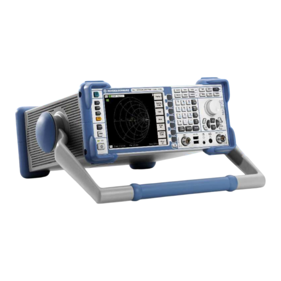
Rohde & Schwarz R&S ZVL Service Manual (170 pages)
Vector Network Analyzer
Brand:
Rohde & Schwarz
| Category:
Measuring Instruments
| Size: 9 MB
Table of Contents
Tabbed Divider Overview
3
Basic Safety Instructions
7
Informaciones Elementales de Seguridad
12
Shipping the Instrument
23
Ordering Spare Parts
24
Refurbished Modules
24
Service and Repair
25
Table of Contents
27
Test Instructions
29
Measurement Equipment and Accessories Appropriate for ZVL3, ZVL3-75 and ZVL6
29
Performance Test R&S ZVL
29
Checking the Frequency Accuracy
31
Checking the Display Linearity
32
Source Power Accuracy
36
Source Power Linearity
37
Checking the Dynamic Range of Test Ports
38
Checking the Trace Noise of Test Ports
38
Performance Test R&S ZVL-K1
39
Measuring Equipment
65
Troubleshooting
66
Repair
71
Instrument Design and Function Description of ZVL3/3-75/6
71
Block Diagram
71
Fig. 3-1 Block Diagram
71
Description of Block Diagram
72
R&S ZVL-Frontend
72
Fig. 3-2 R&S ZVL-Frontend: RF-To-IF Conversion
72
Fig. 3-3 R&S ZVL-Frontend: Generation of First Local Oscillator Frequency
73
Fig. 3-4 ZVL-Frontend: Generation of Second and Third Local Oscillator Frequencies
74
R&S ZVL-Bridge
75
Fig. 3-5 RF-Connections between R&S ZVL-Frontend and R&S ZVL-Bridge
75
Fig. 3-6 R&S ZVL-Bridge: Switch Able Bridges with Attenuator and Preamp
76
Instrument Design and Function Description of ZVL13
77
Fig. 3-7 R&S ZVL-Bridge: Tracking Generator
77
DC Power Supply (Option R&S FSL-B30)
78
Battery Pack (Option R&S FSL-B31)
78
OCXO Reference (Option R&S FSL-B4)
78
Fig. 3-8 RF-Connections between R&S Zvl13_Frontend and R&S Zvl13_Bridge
78
Front Panel
79
Power Supply Module
79
Module Replacement
80
Overview of the Modules
81
Performing a Cold Boot
81
Replacing the Controller A90
82
Opening the Instrument and Removing the Controller
82
Installing the New Controller and Completing the Instruments
83
Putting into Operation
84
Replacing the Lithium Battery on the Controller
85
Danger of Injury
85
Opening the Instrument and Removing the Lithium Battery
85
Installing the New Battery and Completing the Instrument
86
Putting into Operation
86
Replacing Flash Card A60
87
Opening the Instrument and Removing the Controller and Flash Card
87
Installing the New Flash Card and Completing the Instruments
88
Putting into Operation
88
Replacing the TFT Display
89
Opening the Instrument and Removing the Front Module
89
Removing the LVO Displayconnector
90
Removing the LCD
91
Installing the New LCD and Completing the Instrument
91
Replacing the LVO Displayconnector in the Front Module
92
Opening the Instrument and Removing the Front Module
92
Removing the LVO Displayconnector
93
Installing the New LVO Displayconnector and Completing the Instrument
94
Replacing the Push-Button Board Set in the Front Module
95
Opening the Instrument and Removing the Front Module
95
Removing the Push-Button Board Set
96
Installing the New Push-Button Board Set and Completing the Instrument
97
Check the Push-Button Board Set
98
Replacing the Flexible Switchboard in the Front Module
99
Opening the Instrument and Removing the Front Module
99
Removing the Flexible Switchboard
100
Installing the New Flexible Switchboard and Completing the Instrument
101
Check the Flexible Switchboard
102
Replacing the Encoder Board in the Front Module
103
Opening the Instrument and Removing the Front Module
103
Removing the Encoder Board
104
Installing the New Encoder Board and Completing the Instrument
105
Replacing the Front Connector in the Front Module
106
Opening the Instrument and Removing the Front Module
106
Removing the Front Connector
107
Installing the New Front Connector and Completing the Instrument
108
Replacing the Screened Filter Glass in the Front Module
109
Opening the Instrument and Removing the Front Module
109
Removing the Screened Filter Glass
110
Installing the New Screened Filter Glass and Completing the Instrument
111
Replacing RF Cable W1 or RF Cable W2 (MOD03, 06)
112
Opening the Instrument and Removing the Front Module
112
Removing the RF Cable W1 or RF Cable W2
113
Installing the New RF Cable W1 or RF Cable W2 and Completing the Instrument
114
Replacing Adaptor X1 or Adaptor X2 (MOD13)
115
Opening the Instrument and Removing the Front Module
115
Removing the RF Cable W1 or RF Cable W2
116
Installing the New RF Cable W1 or RF Cable W2 and Completing the Instrument
117
Removing the Testport Adapter Insert
118
Installing the New Testport Adapter Insert
118
Replacing the Power Supply
119
Opening the Instrument and Removing the Power Supply
119
Installing the New Power Supply
120
Replacing the Fan
121
Opening the Instrument and Removing the Power Supply
121
Installing the New Fan and Completing the Instrument
122
Replacing the DVI Board A95
123
Opening the Instrument and Removing the DVI Board
123
Installing the New DVI Board and Completing the Instrument
124
Replacing the R&S ZVL-Bridge A200
125
Opening the Instrument and Removing the Board
125
Installing the New R&S ZVL-Bridge Board and Completing the Instrument
126
Replacing the R&S ZVL-Frontend A100
127
Opening the Instrument and Removing the Board
127
Installing the New R&S ZVL-Frontend Board and Completing the Instrument
128
Replacing the Motherboard A10
129
Opening the Instrument
129
Removing Hardware Options and Battery Adapter
129
Removing LPC Cover
130
Removing the R&S ZVL-Bridge Board and R&S ZVL-Frontend Board
130
Removing the Front Module
131
Disconnecting Cables
132
Removing the Motherboard
132
Installing the New Motherboard
133
Putting into Operation
134
Replacing the Battery Adapter Board
135
Opening the Instrument and Removing the Battery Adapter
135
Installing the New Battery Adapter and Completing the Instrument
136
Replacing the Swivel Handle
137
Removing the Handle
137
Installing the New Handle
137
Replacing the OCXO Board (Option R&S FSL-B4)
138
Removing the OCXO Board
138
Installing the New OCXO Board and Completing the Instrument
138
Replacing the Additional Interface (Option R&S FSL-B5)
139
Removing the Additional Interface
139
Installing the New Additional Interface and Completing the Instrument
139
Replacing the IEC/IEEE Bus Board (Option R&S FSL-B10)
140
Removing the IEC/IEEE Bus Board
140
Installing the New IEC/IEEE Bus Board and Completing the Instrument
140
Replacing the DC Power Supply (Option R&S FSL-B30)
141
Removing the DC Power Supply
141
Installing the New DC Power Supply and Completing the Instrument
141
Removing the Battery Pack
142
Installing the New Battery Pack and Completing the Instrument
142
Functional Test
143
Troubleshooting
145
The Following Utilities Are Provided in the R&S ZVL for Diagnostic Purposes
145
Measuring Equipment and Accessories
145
Troubleshooting Start-Up Problems
146
Documents
155
Spare Parts
155
Available Power Cables
155
Spare Parts List
157
Mechanical Drawings
157
List of R&S ZVL Parts Including Spare Parts
159
Block Circuit Diagram
169
Advertisement
Advertisement
Related Products
Rohde & Schwarz R&S ZVL6
Rohde & Schwarz R&S ZNL3
Rohde & Schwarz R&S ZNL4
Rohde & Schwarz R&S ZNB4
Rohde & Schwarz R&S ZNB20
Rohde & Schwarz R&S ZNBT8
Rohde & Schwarz R&S ZNLE3
Rohde & Schwarz R&S ZNLE6
Rohde & Schwarz R&S ZNA67
Rohde & Schwarz R&S ZNB43
Rohde & Schwarz Categories
Measuring Instruments
Test Equipment
Portable Generator
Power Supply
Accessories
More Rohde & Schwarz Manuals
Login
Sign In
OR
Sign in with Facebook
Sign in with Google
Upload manual
Upload from disk
Upload from URL