Sign In
Upload
Manuals
Brands
Rohde & Schwarz Manuals
Measuring Instruments
R&S UPP
Rohde & Schwarz R&S UPP Manuals
Manuals and User Guides for Rohde & Schwarz R&S UPP. We have
1
Rohde & Schwarz R&S UPP manual available for free PDF download: User Manual
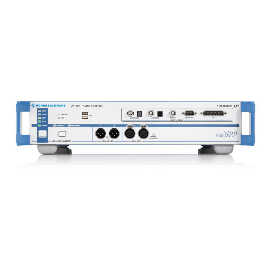
Rohde & Schwarz R&S UPP User Manual (938 pages)
Audio Analyzer
Brand:
Rohde & Schwarz
| Category:
Measuring Instruments
| Size: 16.93 MB
Table of Contents
Table of Contents
19
1 Introduction
35
Documentation Overview
35
2 Startup
37
For Your Safety
35
Key Features
35
Description of the Front View
37
Digital Audio Interfaces
38
USB Connectors
38
Digital Audio/Hdmi Interfaces
39
Multi-Channel Generator
42
Analog Audio Interfaces
43
LAN RESET Button
44
STANDBY Pushbutton
44
Status Leds
45
Description of the Rear Panel
46
Remote-Control Connectors
46
Cascading Connections
47
PC Interfaces
47
AC Supply Voltage Connector
48
Putting into Operation
49
BNC Monitor Outputs
48
Unpacking the Instrument
49
Setting up the Instrument
50
Connecting the R&S UPP to the AC Supply
52
Function Check
55
Presets
55
Windows Operating System
56
Retrieving Computer Hardware Information and Windows Operating System
57
Connecting External Keyboard and Mouse
58
Connecting an External Keyboard
58
Connecting an External Mouse
58
Connecting an External Monitor
58
Changing Screen Resolution of External Monitor under Windows XP
59
Changing Screen Resolution of External Monitor under Windows 7
60
Installing Options
60
Connect R&S UPP to a Network (LAN)
61
Connection to the Network
61
Configuration of R&S UPP for Network Operation
62
Configuration Via LXI
68
Configuration for Manual Remote Operation
74
Firmware Update
78
Troubleshooting During a Firmware Update
78
Windows XP Recovery and Backup
79
Calling the Windows XP Recovery and Backup Partition Menu
79
Backup Current System Partition
80
Restoring a Selected Version of the System Partition
81
Deleting Backups
82
Windows 7 Recovery and Backup
83
Recover Factory Default
82
Calling Windows 7 Recovery and Backup Partition Menu
84
Creating a "User Backup
85
Restoring a "User Backup
85
Restoring Factory Default
85
Deleting Backups
87
3 Getting Started
88
Important Information for Measurements
88
Introduction - Getting Started
88
Maximum Output Voltage of the R&S UPP Generator
88
Avoiding Hum Loops
89
Help System
90
Brief Introduction to Operation
90
The Display
90
Windows User Interface and Controls
90
Panels and Display Windows
92
Quickstart Panel
93
Structure of the Panels and Display Windows
97
Basic Rules of Operation
99
Function Selection and Value Entry
99
Input Help
103
Measurement Functions and Displaying Measurement Results
103
Introduction to Instrument Operation Using Examples
107
Measuring the Frequency Response of an Amplifier, Equalizer, Etc
107
Measuring Total Harmonic Distortion (THD+N) of a DUT
118
Loading Predefined Instrument Setups
126
Introduction - Manual Operation
128
Functional Division of the Audio Analyzer
129
4 Manual Operation
128
Generators
129
Instrument Concept
129
Analyzers
131
General Information on Operation
135
Windows User Interface
135
Operation Using an External Computer Keyboard
136
The Display
138
Operation Using the Mouse
136
The Screens
138
Softkeys
139
Moving and Resizing Panels and Graphical Windows
140
Status Displays and Messages
140
Panels
142
Opening, Operating, Hiding and Closing Panels
142
Panel Structure
143
Navigating in the Panels
147
Settings on the Audio Analyzer
147
Settings in the Panels
147
Changing the Instrument
148
Changing Functions
149
Hiding Parameter Fields
149
Highlighting Controls
150
Activating/Deactivating Functions - Checkboxes
150
Toggling Functions - Radio Buttons
151
Selecting a Parameter - Selection Fields
151
Numeric Entries - Numeric Entry Fields
152
Focus
148
Alphanumeric Entries - Text Entry Fields
155
Display Fields
156
Adopting Parameters - Track Box
157
Input Help
157
Completing Settings
158
Entries During Measurement or Data Output
159
Measurement Displays
159
Measurement Functions and Displaying Measurement Results
160
Numeric Display Field
160
Combo Display
162
Graphical Window
167
Settings in the Menu Bar
186
Settings on the Toolbar
192
Auxiliaries Panel
193
Settings in the Operating System
193
Audio Monitor Function
193
Trigger Output
194
Rapid Deactivation of Outputs
194
Help System
195
File Management
196
Loading and Saving Instrument Settings
196
List of File Extensions Used
197
Manual Remote Operation
198
Units
199
Units in Measurement Result Displays
199
Units for Value Entries
202
Overview of Keys
204
Overview of Panels and Measurement Displays (Graphical Windows)
206
Overview of Status Messages
209
5 Instrument Functions
211
Generator Configuration Panel
211
Configuring Analog Generator
212
Selecting the Generator
211
Analog Generator Config Panel
212
Outputs of the Universal Generator
216
Interface Assignment of the Analog Multichannel Generator
219
Output Power of the Universal Generator
219
Outputs of the Analog Multichannel Generator
219
Output Power of the Analog Multichannel Generator
220
Configuring the Digital Generator
221
Digital Generator Configuration Panel
221
Interface Assignment
226
Configuring the I S Generator
228
I 2 S Generator Configuration Panel
228
Timing Diagrams
234
Interface Assignment
235
Configure HDMI Generator
238
HDMI Generator Configuration Panel
238
Interface Assignment of HDMI
246
Interface Assignment of HEC
246
Signal Flow between R&S UPP and DUT
246
HEAC Support
247
Generator Signals
248
Sine
249
Stereo Sine
251
Multisine
256
Sine Burst
258
Mod Dist
260
Dfd
263
Random
265
Arbitrary
271
Play
272
Polarity
279
DC (Direct-Current Voltage)
280
Chirp
281
Universal
284
Lip Sync
293
Equalization
295
Higher-Level Settings
296
Protocol Generator
296
Setting Bytes as Numerical Values
299
Setting Bytes in Remote-Control Mode
299
Displaying and Setting Parameters in Plain Text
300
Sweeps
301
Activating / Deactivating the Sweep System
302
One-Dimensional Sweep
304
Two-Dimensional Sweep
305
Automatic Sweep
306
Linear and Logarithmic Sweep
308
List Sweep
311
Behavior after Sweep End
313
Sweep Speed
314
Selecting the Analyzer
317
Analyzer Configuration Panel
317
Configure Analog Analyzer
318
Analyzer Configuration Panel
318
Configuring the Digital Analyzer
327
Digital Analyzer Configuration Panel
327
Interface Assignment
330
Configuring the I S Analyzer
332
I 2 S Analyzer Configuration Panel
332
Timing Diagrams
337
Interface Assignment
338
Configuring the HDMI Analyzer
341
HDMI Analyzer Configuration Panel
341
Signal Flow between DUT and R&S UPP
350
Interface Assignment of HDMI
351
Interface Assignment of HEC
351
HEAC Support
352
Starting Measurements
353
Activating and Deactivating Measurement Types
353
Overview of the Measurement System
353
States of the Measurement System
354
Setting Start Condition
358
Start Conditions
358
Time-Controlled Measured Value Recording
365
External Sweeps and Level-Controlled Measured Value Triggering
366
Sweep Options
369
Overview of Sweep Options
369
Activating and Deactivating Sweeps
370
States of the Sweep System
370
Several Sweep Traces in One Diagram
374
Level Measurements
375
Filter Settings
375
RMS Measurement, Broadband
377
RMS Measurement, Selective
379
Peak Measurement
389
DC Voltage Measurement
391
Signal-To-Noise Measurements
391
S/N Measurement Function
393
S/N Sequence in Level Measurements
396
Distortion Measurements
397
General Settings
398
Thd
400
Thd+N & Sinad
405
Mod Dist
412
Dfd
414
Polarity Measurement
416
Frequency Band Analysis
417
Nth Octave Analysis
417
FFT Analysis
424
Size of the FFT
425
Window Function
426
Post FFT
427
FFT Measurement Function
428
Noise Voltage Density
435
Delay Measurement
437
Chirp-Based Measurement
439
Settings
439
Data Buffers
443
Analysis in the Time Domain
446
Waveform Monitor
446
Delay Measurement
452
Protocol Analysis
456
Activating and Configuring the Protocol Analysis
456
Channel-Status Information Display
459
Error Flag Display
460
Lip Sync Analysis
461
BERT Analysis
465
Frequency, Phase and Group Delay Measurement
466
Input Monitor
471
Level Monitor
472
Second Monitor
473
Settling Methods
474
Applications
474
Settling Algorithms
476
Settling for Measurement Functions
476
Settling for Start Conditions (Event-Triggered Measurements)
479
Examples of Settling
482
Filter
482
Analyzer Function Filters
483
Analyzer Prefilter
483
Generator Filters
483
Filter Table
484
User-Definable Filters
485
Filters 01 to 09
486
Lowpass Filter and Highpass Filter
487
Bandpass Filters and Bandstop Filters
488
Notch Filter, Third-Octave Filter and Octave Filter
489
File-Defined Filter
491
Filter Settling Time
493
Weighting Filters
494
Highpass and Lowpass
500
Auxiliaries Panel
501
Switcher Panel
505
Parameters Common to All Filters
493
Connecting Switcher to R&S UPP
505
Default Setting
506
Operation
507
Config Panel
509
Curve, Spectrum and Bar Graph Display
515
Graphical Display, Explanation of the Elements
516
Calling up
522
Parameter Fields of the Panel
524
Softkey Menu
576
Single Scan
581
Trace Group
581
Interpolation on the Common X-Axis
584
Result List
584
Graphical Display, Explanation of the Elements
585
Calling up
587
Parameter Fields of the Panel
587
Softkey Menu
590
Numeric Display
590
Graphical Display, Explanation of the Elements
591
Calling up
594
Parameter Fields of the Panel
594
Softkey Menu
594
Combi Display
594
Graphical Display, Explanation of the Elements
595
Calling up
597
Parameter Fields of the Panel
598
Softkey Menu
612
Limit Monitoring
613
Traces and Bar Graphs
613
Measurement Results
616
Measured Value Sequences
617
Store
618
Equalization Files
618
Trace Files
618
Sweep Lists
619
Limit Files
620
Load
620
Trace Files
620
Equalization Files
628
Limit Files
628
Format
629
Sweep Lists
628
Trace Files
629
Equalization Files
633
Sweep Lists
634
Limit Files
635
Editing
637
Export
642
Loading and Saving
645
Loading and Saving Setups
646
Loading Setups
646
Printing and Saving
646
Printing and Saving Display Screen
646
Saving Setups
646
Configuring Print and Save Operations
647
Graphic Properties
647
6 Remote Control - Fundamentals
654
Starting Print and Save Operations
647
Introduction - Remote Control Fundamentals
654
Brief Instructions
655
IEC Bus
655
Changing to Remote Control
656
Remote Control by IEC/IEEE Bus
656
Remote Control Via LAN Interface
657
Remote Control Via the USB Device Interface
662
Messages
664
Interface Messages
664
Device-Dependent Messages
665
SCPI Command Structure and Syntax
666
Responses to Queries
669
Structure of a Program Message
669
Parameter
670
Overview of Syntax Elements
671
Device Model and Command Processing
672
Input Unit
673
Parser Analyzes
673
Command Sequence (IEC/IEEE)
674
Database and Device Hardware
674
Status Reporting System
675
Command Synchronization
676
Command Recording
677
Output Unit
676
Triggering Measurement or Sweep
676
Recording Commands
678
Starting Recording
678
Editing Commands
679
Status Reporting System
679
Structure of SCPI Status Register
680
Overview of Status Registers
682
Status Byte (STB) and Service Request Enable (SRE) Register
683
IST Flag and Parallel Poll Enable (PPE) Register
684
Status:event Register (ESR)
684
Status:operation Register
685
Status:questionable Register
687
Status:questionable:underrange Register
688
Status:questionable:overrange Register
689
Status:questionable:measuring Register
690
Status:xquestionable Register
691
Use of Status Reporting System
691
Initializing the Status Reporting System
695
7 Remote Control - Command Description
696
Notation of Device-Specific Commands
697
SCPI Parameters
698
Common Commands
700
Generator Settings
704
Selecting the Generator
704
Configuring the Generators
705
Generator Signals
712
Digital Audio Protocol Generator
731
Sweeps
733
Rapid Deactivation of Outputs
736
Analyzer Settings
736
Selecting the Analyzer
736
Configuring the Analog Analyzer
737
Configuring the Digital Analyzer
740
Configuring the I
742
S Analyzer
742
Configure HDMI Analyzer
743
Triggering Measurements and Reading Results
746
Starting Measurements
746
Start Conditions
749
External Sweeps and Level-Controlled Measurement Value Triggering
751
Reading Measurement Results
752
Output of Trace Data Sets
754
Reading out Multi-Channel Records
763
Output of Protocol Data
766
Output of Protocol Errors
766
Sweep Options
767
Selecting Measurement and Mode
768
Level Measurements
770
Filter Settings
770
RMS and RMS Selective Measurement
770
DC Voltage Measurement
773
Signal-To-Noise Measurements
773
Peak Measurement
773
S/N Measurement Function
773
S/N Sequence in Level Measurements
773
Distortion Measurements
774
General Settings
774
Thd
775
Thd+N / Sinad
776
Dfd
777
FFT Analysis
777
Polarity Measurement
777
Chirp Based Measurement
780
Analysis in the Time Domain
782
Protocol Analysis
784
Delay Measurement
785
Lip-Sync Analysis
785
Frequency, Phase and Group Delay Measurement
786
Input, Second and Level Monitor
786
Settling Methods
787
Filters
788
Auxiliaries Panel
793
Switcher
795
Traces, Spectrum Displays and Bargraphs
797
Mod Dist
777
Display Configuration
797
Combi Display
821
Measurement Result Configuration
821
Softkey Commands of the Graphical Display
829
Transferring Trace Data
840
User-Definable Data Buffers
842
Hardcopy
844
Mmemory Subsystem
846
File Naming Conventions
847
Common Mmemory Commands
848
Status Subsystem
851
System Subsystem
860
Clock Lines
866
Trigger Lines
866
Communication Lines
867
Numbering of Channels
868
Configuration of a Cascade
870
Configuration Using CASCADE Button
870
8 Cascading
865
Load and Store Setups
848
Order Code of Instruments
865
Overview
865
Connection of a Cascade
866
Examples of Cascade Configuration
876
Dissolving Cascade
877
Switching Cascade off and on Again
877
Status and Errors During Connection Setup
878
Manual Operation of a Cascade
879
Operating Modes
879
Operating Method
879
Remote Control
883
Distribution of SCPI Commands in Cascade
883
Operating Slaves from Master
883
Query Commands
885
Generators in Cascade
893
Switcher Control in Cascade
893
Changing the AC Supply Fuse
894
Introduction - Maintenance and Interfaces
894
Maintenance
894
Instrument Interfaces
895
9 Maintenance and Instrument Interfaces
894
IEC/IEEE-Bus Interface (IEC 625 / IEEE 488)
895
Ethernet Interface (LAN)
898
USB Device Port
901
Monitor Connection (DVI-D)
902
List of Commands
904
Index
924
Advertisement
Advertisement
Related Products
Rohde & Schwarz R&S UMS100
Rohde & Schwarz R&S UMS120
Rohde & Schwarz R&S UPP Series
Rohde & Schwarz R&S NRP
Rohde & Schwarz R&S NRX-B9
Rohde & Schwarz R&S NGU401
Rohde & Schwarz R&S FSH Series
Rohde & Schwarz R&S ZNB26
Rohde & Schwarz R&S NPA701
Rohde & Schwarz R&S NPA Series
Rohde & Schwarz Categories
Measuring Instruments
Test Equipment
Power Supply
Portable Generator
Accessories
More Rohde & Schwarz Manuals
Login
Sign In
OR
Sign in with Facebook
Sign in with Google
Upload manual
Upload from disk
Upload from URL