Sign In
Upload
Manuals
Brands
Rohde & Schwarz Manuals
Stereo System
GB4000V
Rohde & Schwarz GB4000V Audio Unit Manuals
Manuals and User Guides for Rohde & Schwarz GB4000V Audio Unit. We have
1
Rohde & Schwarz GB4000V Audio Unit manual available for free PDF download: User Manual
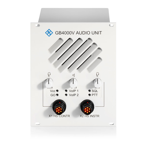
Rohde & Schwarz GB4000V User Manual (70 pages)
Audio Unit
Brand:
Rohde & Schwarz
| Category:
Stereo System
| Size: 1 MB
Table of Contents
Table of Contents
4
User Information
11
General Features
11
Figure 1: the R&S GB4000V Audio Unit, Front View (VAR03)
11
Required Personnel
12
Required Power Supply
12
Design
13
Figure 2: the R&S GB4000V Audio Unit, Rear View
13
Technical Data
14
Table 1: Summary of Technical Data
14
Getting Started
16
Unpacking and Checking
16
Packing, Transport and Storage
16
Installation
17
Figure 3: Dimensions of Panel Cutout (VAR02/03)
18
Figure 4: Dimensions of Panel Cutout (VAR12)
18
Figure 5: Bore Holes for Fixture of the R&S GB4000V
19
Cabling
20
Figure 6: Location of External Interfaces, Rear View of the R&S GB4000V
21
Table 2: Connections on the Rear Panel of the R&S GB4000V
21
Figure 7: External Interface, Front View of the R&S GB4000V (VAR02)
22
Table 3: Connections on the Front Panel of the R&S GB4000V (VAR02)
22
Figure 8: External Interface, Front View of the R&S GB4000V (VAR12)
23
Table 4: Connections on the Front Panel of the R&S GB4000V (VAR12)
23
Figure 9: External Interface, Front View of the R&S GB4000V (VAR03)
24
Table 5: Connections on the Front Panel of the R&S GB4000V (VAR03)
24
Operation
26
General
26
Control Elements and Interfaces
27
Figure 10: Front View of the R&S GB4000V (VAR02)
27
Table 6: Control Elements of the R&S GB4000V (VAR02)
27
Figure 11: Front View of the R&S GB4000V (VAR12)
28
Table 7A: Control Elements of the R&S GB4000V (VAR12)
28
Figure 12: Front View of the R&S GB4000V (VAR03)
29
Table 7: Control Elements of the R&S GB4000V (VAR03)
29
Figure 13: Rear View
30
Table 8: Connections and Control Elements of the R&S GB4000V
30
Indication Via Leds
31
Switching on and off
31
Table 9: Meaning of the LED Display
31
Headset Volume Control
32
Speaker Volume Control
32
IP Reset and Voip Mode Via SETUP Button
32
Firmware Update
33
Device Configuration Via Web Interface
34
Factory Default Settings
34
Table 10: HTTP Page "Configuration
35
Table 11: HTTP Page "Configuration ACL
35
Table 12: HTTP Page "Configuration Voip
36
Device Configuration
37
Content of the Web Interface
37
Table 13: Description of Configuration Interface of the R&S GB4000V
37
Figure 14: Status Page
38
Figure 15: Configuration Page
39
Figure 16: Configuration ACL Page
40
Figure 17: Configuration Voip Page
40
Setting up Connection to the Web Server
41
Meaning of Parameters
42
Website Configuration
42
Table 14: Meaning of Settings of the Network Group
42
Table 15: Meaning of Settings of the Info Group
42
Website Configuration GB2PP
43
Website Configuration Voip
43
Table 16: Meaning of Settings of the Parameter Group
43
Table 17: Meaning of Settings of the ACL Group
43
Table 18: Meaning of Settings of the Voip Configuration Group
44
Device Status
45
Table 19: Meaning of Information of General Status Group
45
Table 20: Meaning of Information of Network Group
45
Table 21: Meaning of Information of Information Group
45
Operation Modes
46
Analog Audio Mode
46
Cabling in the Analog Audio Mode
46
Figure 18: Connector Pin Assignment of the R&S GB4000V Analog Connector Cable
46
Operation in the Analog Audio Mode
47
Voip Mode
48
Introduction/Overview
48
Cabling in the Voip Mode
48
Figure 19: Network Structure of the R&S GB4000V in Voip Mode
48
Operation in the Voip Mode
49
PTT Configuration
50
Figure 20: Configuration of PTT Mode
50
Table 22: Instructor Microphone Logic for the PTT Instructor
51
Table 23: Controller Microphone Logic for the PTT Controller
51
Table 24: Controller Microphone Logic for the External PTT
51
Table 25: Instructor Microphone Logic for the PTT Instructor
52
Table 26: Controller Microphone Logic for the PTT Controller
52
Table 27: Controller Microphone Logic for the External PTT
52
Sidetone
53
Figure 21: Local Sidetone Functionality
54
Figure 22: Remote Sidetone Functionality
54
Malfunction
56
Visual Inspection
56
Other Troubleshooting Measures
56
Table 28: Troubleshooting
57
Maintenance
58
Cleaning
58
Appendix
59
A Technical Information
59
Connector Specifications
59
Figure 23: Headset Controller X1, Recessed Socket, 7-Way, NF7
59
Figure 24: Headset Instructor X2, Recessed Socket, 7-Way, NF7
60
Figure 25: Audio Interface X3, DSUB Female (25Pins)
61
Figure 26: Ethernet - LAN Remote Control X4, RJ-45 (8 Pins) MDI Connector
63
Figure 27: Audio Interface X5, RJ-48 (10 Pins)
64
Figure 28: External Speaker X6, 3-Way Female Connector
65
Figure 29: USB X7, USB-B-S-S-B-TH (4 Pins)
65
Figure 30: Power Connector X8
66
B Drawings
67
C References
68
Advertisement
Advertisement
Related Products
Rohde & Schwarz GP-E
Rohde & Schwarz GP-S
Rohde & Schwarz GC 003
Rohde & Schwarz GSM400-MS
Rohde & Schwarz GSM850-MS
Rohde & Schwarz GSM900-MS
Rohde & Schwarz GSM1800-MS
Rohde & Schwarz GSM1900-MS
Rohde & Schwarz Categories
Measuring Instruments
Test Equipment
Portable Generator
Power Supply
Accessories
More Rohde & Schwarz Manuals
Login
Sign In
OR
Sign in with Facebook
Sign in with Google
Upload manual
Upload from disk
Upload from URL