Table of Contents
Advertisement
Quick Links
Advertisement
Table of Contents
Troubleshooting

Subscribe to Our Youtube Channel
Summary of Contents for Rohde & Schwarz GB4000V
- Page 1 R&S GB4000V ® Audio Unit User Manual 6174.7514.02 – 03...
- Page 2 Subject to change – Data without tolerance limits is not binding. ® R& S is a registered trademark of Rohde & Schwarz GmbH & Co. KG. Trade names are trademarks of the owners. The following abbreviations are used throughout this manual: ® R& S GB4000V is abbreviated as R&S GB4000V...
- Page 3 R&S GB4000V Audio Unit CE Marking The marking by the CE symbol means that the R&S GB4000V audio unit fulfills the EMC guideline and the low-voltage guideline of the European Union. Furthermore it points out that the following technical standards are fulfilled: ●...
-
Page 4: Table Of Contents
R&S GB4000V Audio Unit Table of Contents User Information ...................... 9 General Features ..................... 9 Required Personnel ..................10 Required Power Supply .................. 10 Design ......................11 Technical Data ....................12 Getting Started ...................... 14 Unpacking and Checking ................14 Packing, Transport and Storage .............. - Page 5 R&S GB4000V Audio Unit Maintenance ......................56 Cleaning ......................56 Appendix ........................ 57 Technical Information ..................57 Connector Specifications ................ 57 Drawings ......................65 References ..................... 66 User Manual 6174.7514.02 - 02...
- Page 6 Figure 4: Dimensions of panel cutout (VAR12)............16 Figure 5: Bore holes for fixture of the R&S GB4000V..........17 Figure 6: Location of external interfaces, rear view of the R&S GB4000V....19 Figure 7: External interface, front view of the R&S GB4000V (VAR02)....... 20 Figure 8: External interface, front view of the R&S GB4000V (VAR12).
- Page 7 Table 2: Connections on the rear panel of the R&S GB4000V........19 Table 3: Connections on the front panel of the R&S GB4000V (VAR02)..... 20 Table 4: Connections on the front panel of the R&S GB4000V (VAR12)..... 21 Table 5: Connections on the front panel of the R&S GB4000V (VAR03).
- Page 8 ● Malfunction ● Maintenance ● Technical Information Conventions Used in the Documentation The following conventions are used throughout the R&S GB4000V User Manual: Typographical conventions Convention Description "Links" Links that you can click are displayed in blue font. "References" References to other parts of the documentation are enclosed by quotation marks.
- Page 9 R&S GB4000V Audio Unit Abbreviations Ampere Alternating Current Air Traffic Control Access Control List Auxiliary Bayonet Neill-Concelman Connector Compact Disc European Certificate of Conformity CMOS Complementary Metal Oxide Semiconductor Communication Controller Working Position Depth Decibel Decibel referred to 1 mW dBμV...
- Page 10 R&S GB4000V Audio Unit Maximum Media Access Control Mega Hertz Minimum Millimeter MIL-STD The United States Military Standard Massachusetts Institute of Technology MTBF Mean Time Between Failures Coaxial RF connector standard N Newton meters Personal Computer Push To Talk Request for Comments...
-
Page 11: User Information
User Information General Features The R&S®GB4000V provides audio, PTT and squelch to and from radios in a remote location. The unit is compact and fits into any console. The R&S®GB4000V can be connected to the radios using 4-wire E & M (analog line) or voice over IP (VoIP). When connected using an analog line, either 4-wire E &... -
Page 12: Required Personnel
The personnel must be familiar with this Manual. Required Power Supply The R&S GB4000V operates on an external supply voltage of +19 V DC to +32 V DC (for details on current consumption refer to chapter “1.5”). Additionally, for a backup supply another power supply may be connected. -
Page 13: Design
R&S GB4000V Audio Unit Design The R&S GB4000V is accommodated in a non-magnetic metal case of 19”/4, 3 HU. The R&S GB4000V is switched on and off via the power supply. The main assemblies of the R&S GB4000V are a mounting plate with single board electronic, headset connectors (NF7), loudness control potentiometers and power supply. -
Page 14: Technical Data
R&S GB4000V Audio Unit Technical Data Designation/Type R&S GB4000V audio unit Part No. 6148.3073.02 (1 headset version) 6148.3073.03 (2 headset version) 6148.3073.12 (1 headset version) VAR02 / 03 (mounting in line with IEC 60297): 19”/4, Front Panel (W x H) 3 HU, 106.4 mm x 128.7 mm (4.2. - Page 15 R&S GB4000V Audio Unit User Manual 6174.7514.02 - 02...
-
Page 16: Getting Started
R&S GB4000V Audio Unit Getting Started Unpacking and Checking 1. Check the packaging for damage. 2. Unpack the delivered goods. 3. Check the delivered goods (including accessories) against the delivery note. 4. Check the delivered goods for signs of transport damage. -
Page 17: Installation
After storage or transport in cold weather or if extreme variations in temperature occur, the R&S GB4000V must be slowly adapted to the ambient temperature of the installation site. With condensation, allow at least 12 hours of temperature adjustment before starting For storage observe the environmental data specified in chapter “1.5”. -
Page 18: Figure 3: Dimensions Of Panel Cutout (Var02/03)
R&S GB4000V Audio Unit Figure 3: Dimensions of panel cutout (VAR02/03). Figure 4: Dimensions of panel cutout (VAR12). User Manual 6174.7514.02 - 02... -
Page 19: Figure 5: Bore Holes For Fixture Of The R&S Gb4000V
R&S GB4000V Audio Unit 1. Insert the R&S GB4000V into the control panel or rack at its designated position. 2. Secure the unit by means of four screws passed through the bore holes in the corners of the front panel. -
Page 20: Cabling
R&S GB4000V Audio Unit Avoid strong magnetic fields which can have influence on the audio signals. Avoid strong interfering voltage on the supply lines. This interfering voltage can have influence on the audio signals. Cabling Read the relevant documentation for the equipment before attaching external devices. -
Page 21: Figure 6: Location Of External Interfaces, Rear View Of The R&S Gb4000V
► For normal operation the power supply cable (X8), the headset connector (X1) and the LAN (X4) or audio cable (X5) need to be plugged in. Figure 6: Location of external interfaces, rear view of the R&S GB4000V. Item Connector... -
Page 22: Figure 7: External Interface, Front View Of The R&S Gb4000V (Var02)
Item Connector Function X1 HS CONTR Headset Controller Table 3: Connections on the front panel of the R&S GB4000V (VAR02). 1. Connecting the headset controller including the PTT button using the connector X1 HS CONTR. User Manual 6174.7514.02 - 02... -
Page 23: Figure 8: External Interface, Front View Of The R&S Gb4000V (Var12)
Item Connector Function X1 HS CONTR Headset Controller Table 4: Connections on the front panel of the R&S GB4000V (VAR12). 1. Connecting the headset controller including the PTT button using the connector X1 HS CONTR. User Manual 6174.7514.02 - 02... -
Page 24: Figure 9: External Interface, Front View Of The R&S Gb4000V (Var03)
For details on the connector design and pin-out refer to Appendix Information”. Before connecting the R&S GB4000V to an external power supply, make sure that the requirements are fulfilled in accordance with technical data in chapter “1.5”. User Manual 6174.7514.02 - 02... - Page 25 R&S GB4000V Audio Unit To connect the power supply use the power supply connector included in the mating connector set R&S ZF4000V with the Order No. 6148.3444.02. When preparing the power cable, the following should be observed: Minimum cross-section: 0.2 mm (AWG 24), maximum cross-section: 2.5 mm...
-
Page 26: Operation
R&S GB4000V Audio Unit Operation General Detailed information on how to operate the R&S GB4000V will be given in the following chapters. Using the headsets at a high volume setting for long periods of time can cause hearing damage. User Manual 6174.7514.02 - 02... -
Page 27: Control Elements And Interfaces
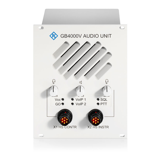
R&S GB4000V Audio Unit Control Elements and Interfaces The R&S GB4000V has control elements and interfaces on the rear and front side. Front view (VAR02) Figure 10: Front view of the R&S GB4000V (VAR02). Item Connector Function Volume Control X1... -
Page 28: Figure 11: Front View Of The R&S Gb4000V (Var12)
R&S GB4000V Audio Unit Front view (VAR12) Figure 11: Front view of the R&S GB4000V (VAR12). Item Connector Function Volume Control X1 Volume Control for the headset connected to X1 HS CONTR Volume Control Volume Control for internal and external loudspeaker (connected to X6... -
Page 29: Figure 12: Front View Of The R&S Gb4000V (Var03)
R&S GB4000V Audio Unit Front view (VAR03) Figure 12: Front view of the R&S GB4000V (VAR03). Item Connector Function Volume Control X1 Volume Control for the headset connected to X1 HS CONTR Volume Control X2 Volume Control for the headset connected to X2 HS INSTR... -
Page 30: Figure 13: Rear View
USB Device Connector (Reserved) X8 DC 19..32 V DC Power supply +19 V DC to +32 V DC X3 AUX Auxiliary Interface Grounding bolt (M5) SETUP Setup button Table 8: Connections and control elements of the R&S GB4000V. User Manual 6174.7514.02 - 02... -
Page 31: Indication Via Leds
Green SQ indicator from radio, receive signal is available Green PTT is activated on the R&S GB4000V Table 9: Meaning of the LED display. Switching On and Off The audio unit has no ON/OFF switch. The device is switched externally via the power supply. -
Page 32: Headset Volume Control
R&S GB4000V Audio Unit Headset Volume Control The audio unit has one (VAR02) or two (VAR03) potentiometers to control the loudness of the headsets connected to X1 HS CONTR or X2 HS INSTR (VAR03 only). Please refer to chapter “3.2”. -
Page 33: Firmware Update
Firmware Update package (.zip file) containing the Linux and FPGA update files shall be present Perform the following steps to do the Firmware Update of the GB4000V Audio Unit: Open the FTP connection to the GB4000V (username: ftp, password: ftp) via ftp client ... -
Page 34: Device Configuration Via Web Interface
The configuration of the audio unit is done via the remote control interface X4 LAN using the HTML based web interface. The URI of the audio unit is not configurable and hardcoded as “GB4000V@IP” where IP is the configurable IP address of the audio unit. -
Page 35: Table 10: Http Page "Configuration
R&S GB4000V Audio Unit Parameter Range Default 9%, 10% External Speaker Volume Off, Min, 2.5%, 5%, 10%, 20%, 30%, 40%, 100% 50%, 60%, 70%, 80%, 90%, 100% –30 to 10, integer values RX Audio Level In-Band PTT Inactive /active Inactive... -
Page 36: Table 12: Http Page "Configuration Voip
R&S GB4000V Audio Unit Parameter Range Default Main URI RX Max. 255 characters rx@192.168.52.101 Main URI TX Max. 255 characters tx@192.168.52.102 Standby URI RX Max. 255 characters Standby URI TX Max. 255 characters DSCP 0 to 63, integer values Microphone input level 1.5 dB, 0 dB, -1.5 dB, -4.5 dB, -9.0 dB, -... -
Page 37: Device Configuration
Content of the Web Interface 3.9.2.1 The web interface of the R&S GB4000V is HTTP-based. The audio unit can therefore be configured and read out using any HTTP-capable web browser. The web interface of the audio unit consists of 4 HTTP pages:... -
Page 38: Figure 14: Status Page
R&S GB4000V Audio Unit Figure 14: Status page. User Manual 6174.7514.02 - 02... -
Page 39: Figure 15: Configuration Page
R&S GB4000V Audio Unit Figure 15: Configuration page. User Manual 6174.7514.02 - 02... -
Page 40: Figure 16: Configuration Acl Page
R&S GB4000V Audio Unit Figure 16: Configuration ACL page. Figure 17: Configuration VoIP page. User Manual 6174.7514.02 - 02... -
Page 41: Setting Up Connection To The Web Server
The meaning of the parameters is explained in chapter “3.9.3”; refer to “Table 14, Table 15, Table 16”. 5. On the Configuration ACL page, the ACL of the R&S GB4000V can be configured. The meaning of the parameters is explained in chapter “3.9.3”; refer to “Table 17”. -
Page 42: Meaning Of Parameters
Impedance RX The audio interface between an R&S RX module and the R&S GB4000V is based on a 600 Ohm system with galvanic isolation. The impedance can be switched to high (600 Ohm) or low (10 Kilo Ohm) impedance. -
Page 43: Website Configuration Gb2Pp
R&S GB4000T. If the ACL is configured, only the R&S GB4000T having an IP address contained in the ACL is allowed to connect to the R&S GB4000V. If no IP address is entered in this list, any unit can connect to the R&S GB4000V. -
Page 44: Table 18: Meaning Of Settings Of The Voip Configuration Group
(Rx or Tx) is configured and the SIP/RTP session is established, the VoIP session is considered as successful A successful VoIP session on the GB4000V is shown with the LED VoIP1 being green. If the LED is orange, the GB4000V considers the session as not successful. -
Page 45: Device Status
3.10 Device Status The status of the R&S GB4000V can be evaluated not only using the LEDs on the front panel of the R&S GB4000V but also using the web interface. For this purpose, a connection to the web interface must be set up in the way described in chapter “3.9.2.2”. -
Page 46: Operation Modes
3.11 Operation Modes The R&S GB4000V can be operated in two different modes. In analog audio mode, the audio and signaling data is transferred to the radio via the analog interface (Audio Interface – X5 AUDIO). In VoIP mode, audio and status data is transferred to the connected radio (RX/TX) via the LAN interface (Ethernet –... -
Page 47: Operation In The Analog Audio Mode
Please take care to avoid acoustic feedback in that case. For proper operation the audio levels of the R&S GB4000V has to be adapted to the audio levels of the radio (see chapter “3.9.3.1”). -
Page 48: Voip Mode
R&S GB4000V Audio Unit 3.11.2 VoIP Mode In VoIP mode the LAN interfaces of the R&S GB4000V and the radio set (RX/TX) are used. Introduction/Overview 3.11.2.1 In VoIP mode, an SIP/RTP connection to the transmitter and/or receiver module is set up. -
Page 49: Operation In The Voip Mode
The audio unit is ready for operation as soon as the GO LED on the front panel of the R&S GB4000V lights up. The LEDs on the front panel indicate the status of the VoIP connection. A more detailed description of the LEDs can be found in chapter “3.3”. -
Page 50: Ptt Configuration
R&S GB4000V Audio Unit 3.11.3 PTT Configuration The effect of different PTT sources is configurable via the web front-end. Figure 20: Configuration of PTT Mode. User Manual 6174.7514.02 - 02... -
Page 51: Table 22: Instructor Microphone Logic For The Ptt Instructor
R&S GB4000V Audio Unit Controller audio mode The state of the instructor microphone in relation to the three possible PTT sources is shown below. The state of the controller microphone and external microphone is given in two independent tables. Instr. PTT = 0 Instr. -
Page 52: Table 25: Instructor Microphone Logic For The Ptt Instructor
R&S GB4000V Audio Unit External audio mode The state of the instructor microphone in relation to the three possible PTT sources is shown below. The state of the controller microphone and external microphone is given in two independent tables. Instr. PTT = 0 Instr. -
Page 53: Sidetone
Sidetone headset = Off Sidetone speaker = Off The sidetone can be taken from the GB4000V RX input port (remote) or from the local microphone port (local), front or rear. In case of VoIP it is configurable, if the sidetone is remote or local. -
Page 54: Figure 21: Local Sidetone Functionality
R&S GB4000V Audio Unit The following picture shows the local sidetone functionality of the GB4000V. Please note that local sidetone is applicable for VoIP mode, only. Its main purpose is to reduce the echo for the air traffic controller in VoIP mode caused by latency of VoIP RTP audio packets (up to 200ms) signaled back from Rx module. - Page 55 R&S GB4000V Audio Unit User Manual 6174.7514.02 - 02...
-
Page 56: Malfunction
Malfunction Visual Inspection 1. Check external cabling between the R&S GB4000V and external equipment. 2. Check all connectors for good contact and the cables at the rear for mechanical damage. If necessary, replace cables by new ones, one at a time, until the defective connection has been found. -
Page 57: Table 28: Troubleshooting
R&S GB4000V Audio Unit Error Possible Cause Remedy A VoIP connection is active, but Loudness of speakers or Increase the volume of the headsets is set up to “low”. no audio signals are audible on speakers or headsets. speakers or headsets. -
Page 58: Maintenance
R&S GB4000V Audio Unit Maintenance Cleaning The front side of the R&S GB4000V can be cleaned with a lint-free moistened cloth. In order to avoid damage to the front panel please note that: ● No high pressure cleaners and steam jet shall be used ●... -
Page 59: Appendix
R&S GB4000V Audio Unit Appendix A Technical Information Connector Specifications Headset Controller X1 HS CONTR Figure 23: Headset Controller X1, recessed socket, 7-way, NF7. Column D (Direction): O = Output I = Input B = Bidirectional Column T (Type): A = Analog... -
Page 60: Figure 24: Headset Instructor X2, Recessed Socket, 7-Way, Nf7
R&S GB4000V Audio Unit Headset Instructor X2 HS INSTR (VAR03) Figure 24: Headset Instructor X2, recessed socket, 7-way, NF7. Column D (Direction): O = Output I = Input B = Bidirectional Column T (Type): A = Analog D = Digital... -
Page 61: Figure 25: Audio Interface X3, Dsub Female (25Pins)
R&S GB4000V Audio Unit Auxiliary Interface X3 AUX Figure 25: Audio interface X3, DSUB female (25pins). Column D (Direction): O = Output I = Input B = Bidirectional Column T (Type): A = Analog D = Digital P = Power... - Page 62 R&S GB4000V Audio Unit Column D (Direction): O = Output I = Input B = Bidirectional Column T (Type): A = Analog D = Digital P = Power Column TI (Test Instructions): P = Test Value T = Trimming Value D = Type Test Value...
-
Page 63: Figure 26: Ethernet - Lan Remote Control X4, Rj-45 (8 Pins) Mdi Connector
R&S GB4000V Audio Unit Ethernet – LAN Remote Control X4 LAN Figure 26: Ethernet – LAN remote control X4, RJ-45 (8 pins) MDI connector. Column D (Direction): O = Output I = Input B = Bidirectional Column T (Type): A = Analog... -
Page 64: Figure 27: Audio Interface X5, Rj-48 (10 Pins)
R&S GB4000V Audio Unit Audio Interface X5 AUDIO Figure 27: Audio interface X5, RJ-48 (10 pins). Column D (Direction): O = Output I = Input B = Bidirectional Column T (Type): A = Analog D = Digital P = Power... -
Page 65: Figure 28: External Speaker X6, 3-Way Female Connector
R&S GB4000V Audio Unit External Speaker X6 EXT SP Figure 28: External speaker X6, 3-way female connector. Column D (Direction): O = Output I = Input B = Bidirectional Column T (Type): A = Analog D = Digital P = Power... -
Page 66: Figure 30: Power Connector X8
R&S GB4000V Audio Unit Power Connector X8 DC 19 to 32 V Figure 30: Power connector X8. Column D (Direction): O = Output I = Input B = Bidirectional Column T (Type): A = Analog D = Digital P = Power... -
Page 67: B Drawings
R&S GB4000V Audio Unit B Drawings User Manual 6174.7514.02 - 02... -
Page 68: C References
R&S GB4000V Audio Unit C References ED-137_Part 1.doc, Final Draft 1.2, December 2008 https://tools.ietf.org/html/rfc3261, April 2010 User Manual 6174.7514.02 - 02... - Page 69 R&S GB4000V Audio Unit Index Analog audio mode .......... 44 Metal case ............11 Backup power supply........23 Operation ............24 Bore holes ............17 Operation modes..........44 Cabling ............18 Packing ............14 Cleaning ............56 Panel cutout ............ 16 Condensation ..........
- Page 70 R&S GB4000V Audio Unit User Manual 6174.7514.02 - 01...
Need help?
Do you have a question about the GB4000V and is the answer not in the manual?
Questions and answers