Sign In
Upload
Manuals
Brands
Rohde & Schwarz Manuals
Power Supply
FSQ8
Rohde & Schwarz FSQ8 Manuals
Manuals and User Guides for Rohde & Schwarz FSQ8. We have
2
Rohde & Schwarz FSQ8 manuals available for free PDF download: Service Manual, Quick Start Manual
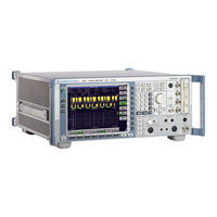
Rohde & Schwarz FSQ8 Service Manual (406 pages)
Signal Analyzer
Brand:
Rohde & Schwarz
| Category:
Measuring Instruments
| Size: 8 MB
Table of Contents
Contents - Chapter 1 "Performance Test"
28
Table of Contents
28
Performance Test
30
Test Instructions
30
Measuring Equipment and Accessories
34
Performance Test R&S FSQ
35
Checking the Reference Frequency Accuracy
35
Checking Immunity to Interference
36
St if Image Frequency Rejection
37
Nd if Image Frequency Rejection
37
Rd if Image Frequency Rejection
37
St if Rejection
38
Nd if Rejection
38
Checking Nonlinearities
39
Third-Order Intercept Point
39
Second-Order Harmonic Distortion
40
Checking if Filters
41
Checking the Bandwidth Switching Level Accuracy
41
Checking Bandwidth
42
Checking the Shape Factor
42
Checking Noise Display
43
Checking the Level Accuracy and the Frequency Response
44
Frequency Response > 3.6 Ghz
46
Checking the Display Linearity
50
Checking the Display Linearity (Alternative Measurement)
52
Checking the RF Attenuator
57
Checking the RF Attenuator Accuracy (Alternative Measurement)
59
Checking the Reference Level Switching (IF-Gain)
61
Checking the Reference Level Switching Accuracy (Alternative Measurement)
63
Checking the Phase Noise for Instruments with Serial Numbers Smaller than 200000
65
Testing the Phase Noise at 639 Mhz or 640 Mhz for Instruments with Serial Number Larger than 200000
67
Alternative Phase-Noise Testing at 800 Mhz for Instruments with a Serial Number Larger than 200000
69
Checking the Return Loss at the RF Input
72
Checking the Frequency Response of the IQ Compensation Filter
73
Checking the Output Level
74
Test Procedure Option Tracking Generator B9 with Option Attenuator B12
74
Checking the Frequency Response
75
Checking the Dynamic Range
76
Checking Modulation
77
Checking the I/Q Modulator
77
Checking the Amplitude Modulation
78
Checking the Frequency Modulation
79
Performance Test Option Preamplifier FSU-B24
81
Checking Noise Display
81
Checking the Level Accuracy and the Frequency Response
82
Absolute Level Accuracy at 128 Mhz
83
Frequency Response < 3.6 Ghz
84
Performance Test Option Electronic Attenuator B25
89
Checking Noise Display with Preamplifier (B25)
89
Checking the Level Accuracy and the Frequency Response with Preamplifier
90
Frequency Response > 3.6 Ghz
97
Checking Nonlinearities with Electronic Attenuator
100
Third-Order Intercept
100
Checking the RF Attenuator (with Option B25)
101
Checking the RF Attenuator Accuracy with Option B25 (Alternative Measurement)
102
Checking the Electronic Attenuator Accuracy
104
Checking the Electronic Attenuator Accuracy with Option B25 (Alternative Measurement)
105
Checking LO-Level
107
Performance Test Option External Mixing B21
107
Checking the Input lo out / if in (2-Port-Mixers)
108
Checking the Input if in (3-Port-Mixers)
108
Checking the Bias Supply
109
Performance Test Option - B23
110
Checking Noise Display with Preamplifier (B23)
110
Checking the Level Accuracy and the Frequency Response with Preamplifier (B23)
111
Test Procedure for Option IQ Baseband Input FSQ-B71
114
Testing the Level Error (50 )
118
Checking the Level Error (1 K / 1M )
123
Dynamic Range (1 K / 1 M )
125
Test Procedure for Option I/Q Bandwidth Extension R&SFSQ-B72
127
Test Procedure for Option Digital Baseband Interface R&SFSQ-B17
145
Performance Test Report R&S FSQ
146
Performance Test Report Option R&S FSU-B9
168
Performance Test Report Option R&S FSU-B24
168
Performance Test Report Option B25
175
Performance Test Report Option FSU-B21
181
Performance Test Report Option B23
182
Performance Test Report Option R&S FSQ-B71
184
Performance Test Report Option R&S FSQ-B72
198
Performance Test Report Option R&S FSQ-B17
210
Contents - Chapter 2 "Adjustment"
212
Adjustment
214
Service Menu
214
Adjustment Functions
215
Entering the Password
215
Manual Adjustment
216
Measuring Equipment and Accessories
216
Test Instructions
216
Adjusting the Level Measurement Accuracy
217
Adjusting the Frequency Accuracy
219
Adjustment of Module Data
221
Frequency Response Correction
221
Contents - Chapter 3 "Repair"
222
Block Diagram
224
Fig. 3-1 Block Diagram of Instrument
224
Instrument Design and Function Description
224
Repair
224
Description of Block Diagram
225
Fig. 3-2 Input Attenuator
225
Fig. 3-3 Conversion of the RF to the Third if from 20 Hz to 3.6 Ghz
226
Fig. 3-4 Conversion of the RF to the if from 3.6 Ghz
227
Fig. 3-5 if Filter
228
Fig. 3-6 Processing of Measured Data
229
Fig. 3-7 Synchronization of 1St Local Oscillator
230
Fig. 3-8 Sweep Synthesizer
232
Module Replacement
235
Performing a Cold Start
236
Fig. 3-9 Removing the Front Module Controller
239
Replacing Front Module Controller A90
239
Fig. 3-10 Position of Connectors on Front Module Controller
240
Replacing Lithium Battery on Front Module Controller
241
Fig. 3-11 Position of Lithium Battery on Front Module Controller
242
Replacing Hard Disk A60
244
Replacing LCD and DC/AC Converter in Front Module
246
Fig. 3-12 Position of Connectors on Front Module Controller
247
Replacing Keyboard Membrane or Mat on Front Module
248
Fig. 3-13 Position of Connectors on Front Module Controller
249
Replacing Front Cover on Front Module
250
Replacing Floppy Disk Drive A30
251
Replacing Power Supply A20
252
Replacing Fan E1
253
Replacing RF Input Connector (Cable W1) R&S FSQ3/8
254
Replacing RF INPUT Connector (Testport Adapter) R&S FSQ26
255
Replacing RF-INPUT (Testport Adapter) R&S FSQ26
256
Replacing Motherboard A10
257
Replacing RF Attenuator A40
259
Replacing Probe Board Module A80 and Vol./Phone Board A191
261
Fig. 3-14 Pin Assignments of PROBE POWER Connector
262
Replacing USB2.0 Board A310
263
Replacing RF Frontend A100
265
Replacing Synthesizer A110
266
Replacing Detector A140
268
Replacing if Filter A130
269
Replacing 8 Ghz Converter Unit A160; FSQ8
270
Replacing Diplexer A162; FSQ8
272
Replacing 8 Ghz YIG Unit A161; R&S FSQ8
274
Replacing Relay on the MW Converter Unit; FSQ8
276
Replacing 26.5 Ghz MW Converter Unit A160; FSQ26/40
278
Replacing Diplexer A161; FSQ26/40
280
Replacing 26.5 Ghz YIG Unit 162; FSQ 26/40
282
Replacing Extender 26,5 Ghz A163; FSQ 26/40
284
Replacing Relay on the MW Converter Unit; FSQ26/40
286
Replacing Tracking Generator A170 (Option: B9)
288
Replacing Generator Attenuator A171 (Option: B12)
289
Replacing OCXO A200 (Option: B4)
290
Replacing Combo Drive A381 (Option: B18)
291
Replacing External Generator Control A210 (Option: B10)
292
Replacing Baseband Input 1 A270 (Option: B71)
294
Replacing Baseband Input 2 A260 (Option: B71)
295
Replacing I/Q Bandwidth Extension A280 (Option B72)
296
Replacing External Mixer Board A180 (Option B21)
298
Replacing Diplexer Board with Preamplifier A161; (Option B23)
299
Replacing Electronic Attenuator A50 (Option B25)
301
Replacing I/Q Memory Extension (Option B100)
302
Replacing Memory Modules (Option B102)
304
Replacing Preamplifier A50 (Option B24)
305
Replacing IQ DATA IN/OUT A290 (Option B17)
306
Measuring Equipment and Accessories
308
Troubleshooting Switch-On Problems
309
Troubleshooting Problems with Booting
310
Troubleshooting - Loading Module Eeproms
316
Troubleshooting Via Selftest
318
Troubleshooting RF Converter 1
335
Troubleshooting
336
Troubleshooting MW Converters
336
Troubleshooting - Wideband Detector Unit
339
Fig. 3-15 Video Path Differential Linearity Test, Error-Free Unit
340
Fig. 3-16 Video Path Differential Linearity Test, Faulty Unit (Blocked Bit)
340
Fig. 3-17 FFT Test, Noise Floor, Error-Free Unit
341
Fig. 3-18 Full-Scale Test, Error-Free Unit
342
Fig. 3-19 Phase Noise Test, Error-Free Unit
344
Fig. 3-20 Phase Noise Test, Faulty Unit (High Phase Noise)
344
Contents - Chapter 5 "Documents"
352
Documents
354
Shipping of a Module
354
Shipping of Instrument
354
Shipping of Instrument and Ordering of Spare Parts
354
Ordering Spare Parts
355
Refurbished Modules
355
Taking Back Defective Replaced Modules
355
Available Power Cables
356
Spare Parts
356
Mechanical Drawings
358
Spare Part List
358
Advertisement
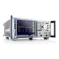
Rohde & Schwarz FSQ8 Quick Start Manual (229 pages)
Signal Analyzer
Brand:
Rohde & Schwarz
| Category:
Measuring Instruments
| Size: 4 MB
Table of Contents
Table of Contents
19
1 Front and Rear Panel
29
Front View
30
Function Keys on the Front Panel
32
Front Panel Connections
34
Rear View
38
Rear Panel Connections
40
2 Preparing for Use
51
Preparing for Operation
54
Unpacking the Instrument
54
Setting up the Instrument
55
Installation in a 19" Rack
56
Connecting the Instrument to the AC Power Supply
56
Switching on the R&S FSQ
56
Functional Test
57
Switching off the R&S FSQ
58
Cleaning the Outside
58
Instrument Drive Usage
59
Connecting External Devices
60
Connecting an External Keyboard
60
Connecting a Mouse
62
Connecting an External Monitor
63
Connecting a Printer
64
Connecting USB Devices (E.g. a Power Meter)
65
Connecting External Generators
67
Configuring the Generator on the R&S FSQ
68
Connecting the R&S FSQ to the Generator
68
Generator
69
Setting the Output Level
69
Using an External Generator as a Tracking
70
Setup
71
Selecting the Frequency Reference
71
Setting the Date and Time
72
Setting the GPIB Interface
73
GPIB Address
73
GPIB Language
73
ID Response String
75
Setting the Screen Colors
76
Automatically Switching off the Internal Screen
77
File and Path Selection Using the Front Panel Keys
78
Selecting and Configuring Printers
80
Selecting Alternative Printer Configurations
81
Selecting Printer Colors
81
Installing Plug&Play Printers
83
Installing Non-Plug&Play Printers
83
Configuring the LAN Interface
84
Connecting the Instrument to the Network
84
Configuring the Network Card
85
Configuring the Interface
85
Driver Installation
85
Configuring Existing Network Protocols
86
Services
89
LXI Configuration
90
LXI Configuration Dialog
91
LXI Browser Interface
91
LAN Configuration Website
92
Ping
92
Operating System Properties
93
Properties Specific to Windows
93
Properties Specific to Windows XP
93
Windows XP Service Packs
93
Opening the Windows XP Start Menu
94
Windows XP Software Approved for the Instrument
94
3 Firmware Update and Installation of Firmware
95
Options
95
Firmware Update
96
Activating Firmware Options
97
4 Basic Operation
99
Diagram Layout
100
Displays in the Diagram Area
101
Setting Parameters
105
The Keypad
105
The Rotary Knob and Arrow Keys
106
Editing Numeric Parameters
106
Editing Alphanumeric Parameters
107
Alphanumeric Editor Type 1
107
Alphanumeric Editor Type 2
108
5 Basic Measurement Examples
111
Measuring a Sinusoidal Signal
113
Measuring the Level and Frequency with Markers
113
Procedure
113
Increasing the Frequency Resolution
114
Setting the Reference Level
115
Counter
116
Measuring Harmonics of Sinusoidal Signals
118
Measuring the Suppression of the First and Second Harmonic of an Input Signal
118
Reducing Noise
120
Measuring Harmonics with Frequency Sweeps
122
High-Sensitivity Harmonics Measurements
122
Measuring Signal Spectra with Multiple Signals
125
Separating Signals by Selecting the Resolution
125
Separating Two Signals with a Level of -30 Dbm each at a Frequency Spacing of 30 Khz
125
Measuring the Modulation Depth of an AM-Modulated Carrier in the Frequency Domain
129
Measurements in the Time Domain
131
Measuring the Power Characteristic
131
Example - Measuring the Power of a GSM Burst During the Activation Phase
131
Measuring the Power Characteristic of Burst Signals
133
Example - Measuring the Edges of a GSM Burst with High Time Resolution
133
Measuring the Signal-To-Noise Ratio of Burst Signals
135
Example - Signal-To-Noise Ratio of a GSM Signal
135
Measurement of AM-Modulated Signals
138
Example - Displaying the AF of an AM-Modulated Signal in the Time Domain
138
Measurement of FM-Modulated Signals
140
Carrier
140
Example - Display of the AF of an FM-Modulated Carrier
140
Storing and Loading Instrument Settings
143
Storing an Instrument Configuration (Without Traces)
143
Storing Traces
144
Loading an Instrument Configuration
145
Booting
146
Printing out the Measurement Results
147
Selecting the Color Setting for the Printout
147
Additional Measurement Examples
148
6 LAN Interface
149
Installing Additional Network Protocols & Services
151
Configuration Examples
154
Subsequent Changes to the Network Configuration
154
Configuring the Windows XP Firewall
156
Operating the Instrument Without a Network
157
Operating the Instrument in a Network
158
Creating Users
158
Changing the User Password
160
NOVELL Network Only: Configure NOVELL Client
162
Logging on to the Network
163
Deactivating the Automatic Login Mechanism
163
Reactivating the Automatic Login Mechanism
163
Using Network Drives
164
Installing a Network Printer
166
Sharing Directories (Only with Microsoft Networks)
170
Manual Operation of the R&S FSQ with XP Remote
172
Desktop
172
Introduction
172
Configuring the R&S FSQ for Use of XP Remote Desktop
173
Configuring the Controller
176
Connection Setup with the R&S FSQ
179
Interrupting and Restoring the Remote Desktop Connection with the R&S FSQ
182
Deactivating the R&S FSQ from the Controller
182
7 Brief Introduction to Remote Control
183
Basic Steps in Programming Using the VISA Interface
185
Linking the VISA Library for Visual Basic
185
Programming Notes
185
Initialization and Default State
187
Creating Global Variables
187
Initializing the Controller
187
Initializing the Instrument
187
Configuring the Power Save Function for the Display
188
Switching the Screen Display on and off
188
Sending Simple Instrument Setting Commands
189
Reading out Instrument Settings
190
Marker Positioning and Readout
191
Command Synchronization
192
Reading Error Messages
193
Reading Output Buffers
193
Detailed Programming Examples
194
Default Settings of the R&S FSQ
194
Setting the IEC Bus Status Registers
194
Default Settings for Measurements
195
Marker Search Functions, Restricting the Search
197
Range
197
Using Markers and Delta Markers
197
Frequency Counting
198
Fixed)
199
Working with a Fixed Reference Point
199
Measuring Noise and Phase Noise
200
Reading out Trace Data
202
Storing and Loading Instrument Settings
205
Storing Instrument Settings
205
Loading Instrument Settings
206
Setting the Data Record for Startup Recall
206
Configuring and Starting a Printout
207
Appendix
209
Appendix A: Printer Interface
211
Installing USB Printers
212
Installing Non-Plug&Play Printers
215
Local Printer
215
Network Printer
219
Appendix B: External Generator Control
221
List of Generator Types Supported by the R&S FSQ
221
Advertisement
Related Products
Rohde & Schwarz R&S FSV-B30
Rohde & Schwarz R&S FSV-B31
Rohde & Schwarz FSQ series
Rohde & Schwarz FSQ31
Rohde & Schwarz FSQ3
Rohde & Schwarz FSQ26
Rohde & Schwarz FSQ40
Rohde & Schwarz FSV-B32
Rohde & Schwarz FSV-B34
Rohde & Schwarz FSQ
Rohde & Schwarz Categories
Measuring Instruments
Test Equipment
Portable Generator
Power Supply
Accessories
More Rohde & Schwarz Manuals
Login
Sign In
OR
Sign in with Facebook
Sign in with Google
Upload manual
Upload from disk
Upload from URL