Sign In
Upload
Manuals
Brands
Rohde & Schwarz Manuals
Measuring Instruments
EVSG-K5
Rohde & Schwarz EVSG-K5 Manuals
Manuals and User Guides for Rohde & Schwarz EVSG-K5. We have
1
Rohde & Schwarz EVSG-K5 manual available for free PDF download: User Manual
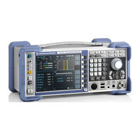
Rohde & Schwarz EVSG-K5 User Manual (418 pages)
VHF/UHF Airnav/Com Analyzer
Brand:
Rohde & Schwarz
| Category:
Measuring Instruments
| Size: 11 MB
Table of Contents
Table of Contents
3
1 Getting Started
13
Safety Information
13
Safety Instructions
13
Labels on the Product
17
Warning Messages in the Documentation
17
Documentation Overview
18
Data Sheets and Brochures
18
Getting Started Manual
18
Printed Safety Instructions
18
User Manuals and Help
18
Release Notes and Open-Source Acknowledgment (OSA)
19
Key Features
19
Preparing for Use
19
Choosing the Operating Site
20
Lifting and Carrying
20
Unpacking and Checking
20
Mounting the R&S EVSG1000 in a Rack
21
Placing the R&S EVSG1000 on a Bench Top
21
Setting up the R&S EVSG1000
21
Setting up the R&SEVSG1000
21
Portable Operation
22
Connecting to Power
22
Connecting an External DC Power Source
23
Connecting the Provided AC/DC Power Supply Connector
23
Using an Optional Battery Pack (R&S EVSG-B3)
24
Switching on or off
25
Performing an Auto-Calibration
26
Connecting Devices for Signal Input and Output
27
Connecting to LAN
27
Instrument Tour
28
Front Panel
28
Power Key
29
Display
29
Rx1 in / Rx2 in
29
Usb
29
AF out
30
DC out
30
System Keys
30
Softkeys
30
Function Keys
30
Keypad
31
Navigation Keys
32
Rear Panel
33
Power Supply
33
Li-Ion Battery Pack
34
LAN (Ethernet)
34
Rs232 Gps
34
PPS in
34
Trigger in
34
LF in (Baseband/Low Frequency Input)
34
Demod out
35
Loudspeaker
35
Rotary Knob
32
Device ID
35
Accessories
35
Operating Basics
38
Understanding the Display Information
38
Manual Operation
40
Changing Settings and Activating Functions
40
Entering Data
41
Getting Help
43
Manual Operation from a VNC Viewer
44
Remote Control
47
Input Signal Settings
51
Measurement Mode
52
Receiver Board
52
ILS Localizer and ILS Glidepath (GP) Modes
54
Localizer Basics
54
Glide Slope Basics
55
ILS Localizer and Glidepath Measurements and Results
56
2 Measurements and Results
48
3 Configuring the Input Signal and Measurement Mode
51
RF Level and Frequency Display
61
IF Spectrum Preview
62
LF Level, Frequency, and Spectrum Display
63
ILS Localizer and Glidepath Main View
64
ILS Localizer Distortion View
69
ILS Localizer ID Analysis View
71
ILS Localizer Recording View
74
ILS Localizer and Glidepath Configuration
75
Configuring the Input Signal
75
Channel and Frequency Configuration
76
Ampt
80
Bandwidth (BW)
81
LF Input Configuration
82
DDM and SDM Configuration
86
Basics on Marker Beacons
87
ILS Marker Beacon Mode (Option R&S EVSG-K3)
87
ILS Marker Beacon Measurements and Results
88
Setting the Measurement Time (Mtime)
86
RF Level and Frequency Display
89
IF Spectrum Preview
90
ILS Marker Beacon Main View
91
ILS Marker Beacon ID Analysis
92
ILS Marker Beacon Recording View
94
Configuring ILS Marker Beacon Measurements
95
Setting the Receiver Frequency
95
Ampt
96
Setting the Measurement Time (Mtime)
97
VOR Mode (Option R&S EVSG-K2)
97
VOR Basics
98
VHF Omni Directional Radio Range (VOR)
98
VOR Demodulator
101
Phase Notation in vor Measurements
103
VOR Measurements and Results
104
RF Level and Frequency Display
105
IF Spectrum Preview
106
VOR Main View
106
VOR Distortion View
108
VOR ID Analysis View
110
VOR Recording View
112
Configuring vor Measurements
113
General Measurement Configuration
113
Channel Frequency Configuration (CH FREQ)
115
Ampt
116
Bandwidth (BW)
117
Setting the Measurement Time (Mtime)
117
COM Measurement Results
118
COM Mode (Option R&S EVSG-K6)
118
RF Level and Frequency Display
119
IF Spectrum Preview
120
COM Main View
121
COM Recording View
123
COM Configuration
124
Channel and Frequency Configuration
124
Ampt
126
Bandwidth (BW)
127
Setting the Measurement Time (Mtime)
127
Basics on Non-Directional Beacons
128
NDB Measurement and Results
128
Non-Directional Beacon Mode (Option R&S EVSG1-K7)
128
RF Level, Frequency and if Spectrum Display
129
NDB ID Analysis
130
NDB Distortion View
132
NDB Recording View
133
Configuring NDB Measurements
134
General Measurement Settings
135
Receiver Frequency
135
Amplitude
136
Setting the Bandwidth
137
Setting the Measurement Time (Mtime)
137
4 Numeric Measurement Modes
54
5 Graphic Measurement Modes
139
RF Spectrum Mode (Option R&S EVSG-K10)
139
Configuring the Frequency Range
140
Configuring the Bandwidth
141
Configuring the Amplitude (Y-Axis)
142
Configuring the Trace
143
IF Spectrum Mode (Option R&S EVSG-K10)
144
Configuring the Frequency Range
145
Configuring the Amplitude (Y-Axis)
146
Configuring the Bandwidth
146
Configuring the Trace
148
AF Spectrum Mode (Option R&S EVSG-K11)
149
Configuring the Input Signal
151
Configuring the Frequency Range
152
Configuring the Bandwidth
153
Configuring the Amplitude (Y-Axis) for RF Input
154
Configuring the Amplitude (Y-Axis) for LF Input
155
Configuring the Trace
157
AF Time Domain Mode (Option R&S EVSG-K12)
158
Configuring the Input Signal
161
Configuring the Amplitude (Y-Axis) for RF Input
162
Configuring the Frequency Range and Bandwidth
162
Configuring the Amplitude (Y-Axis) for LF Input
163
Configuring the Measurement Time
165
Configuring the Trigger
165
Configuring the Trace
166
Using Markers in the Graphical Displays
167
Basics on GBAS and SCAT-I Analysis
171
6 GBAS/SCAT-I Mode (Options R&S EVSG-K4/-K5)
170
GBAS Specifics
171
Broadcast Timing Structure
173
Final Approach Segment (FAS) Construction Data
173
Time Slot Synchronization Via PPS
174
GBAS / SCAT-I Measurement Information
174
GBAS / SCAT-I Measurement Views and Results
176
Sequence View
176
Frame View
178
Frame Power Vs. Time Diagram
179
Frame Results Table
180
Burst View
182
Slot Power Vs. Time Diagram
183
Slot Results Table
184
Constellation View
185
Message View
186
Recording View
187
GBAS/ SCAT-I Measurement Configuration
189
View Configuration
189
Frequency Configuration
190
Amplitude Configuration
191
Bandwidth Configuration
191
General Configuration
192
Message XML Interface
193
General Processing
194
Output Elements and Control Elements
195
XML File Format Description
198
Format Description of Elements
200
Output Elements
200
Unsigned Type
200
Signed Type
201
Longitude Type
202
Latitude Type
203
ID Type
204
Fixed Type
204
Value Type
204
FEC Type
205
CRC Type
205
List Type
206
Enum Type
207
Dummy Type
208
Control Elements
208
Link_Sel Type
208
Loop Type
211
While Type
211
Auxiliary Elements
212
Fill Type
212
7 Power Sensor Support (Option R&S EVSG-K24)
213
8 Data Management
215
Storage and Recall Functions
215
Recording Measurement Data
217
Storing and Recalling Measurement Settings (Preset)
215
GPS Data Synchronization
218
I/Q Data Recording and Streaming (R&S EVSG1-K25)
218
Recording Settings
219
Activating Data Recording
221
Analyzing Recorded I/Q Data
223
Creating and Storing Screenshots
223
9 Common Instrument Settings
226
Viewing Recorded Data
223
Audio Output Settings
226
Display
227
Demodulation Output Settings
229
Network (Remote) Settings
230
System Settings
232
Auto-Calibration (Cal)
234
Instrument Configuration and Operating Status Settings
234
Error Log
235
Copy to USB
236
Delete All Error Messages
236
HW Status
236
Installed Options
237
Inventory
238
Power Supply and Battery Charge State
239
SW Update
239
GPS Configuration
240
Common Instrument and Measurement Setup
242
10 Remote Commands
242
Common Measurement Settings
243
Signal Input
247
Baseband Input
249
Trigger Settings
249
Result Display Settings
250
Audio, Demodulation and Output Configuration
253
Retrieving Instrument Information
258
GPS Data
261
System Settings
266
Calibration
269
Network Settings and Remote Operation
270
Deprecated Commands
271
Configuring ILS Localizer Measurements
273
Configuring the ILS LOC and GP Modes
273
ILS Localizer (LOC) and Glidepath (GP) Modes
273
Configuring ILS Glidepath Measurements
283
Retrieving ILS Loc and GP Results
292
Retrieving ID Results
301
Deprecated Commands
302
Configuring ILS MB Measurements
305
ILS Marker Beacon (MB) Mode
305
Retrieving ILS MB Results
307
Retrieving ILS MB Identifier Results
309
Deprecated Commands
311
Configuring vor Measurements
312
VOR Mode
312
Retrieving vor Results
316
Deprecated Commands
321
COM Mode
322
Configuring COM Measurements
322
Retrieving COM Results
326
Configuring GBAS/ SCAT-I Measurements
333
GBAS/ SCAT-I Mode
333
Retrieving GBAS/ SCAT-I Results
337
Configuring an NDB Measurement
345
NDB Mode
345
Retrieving NDB Measurement Results
348
Configuring RF Spectrum Measurements
350
RF Spectrum Mode
350
Retrieving RF Spectrum Results
354
Configuring if Spectrum Measurements
355
IF Spectrum Mode
355
AF Spectrum Mode
359
Configuring AF Spectrum Measurements
359
Retrieving if Spectrum Results
359
Retrieving AF Spectrum Results
366
AF Time Domain Mode
367
Configuring AF Time Domain Measurements
367
Data Management
372
Data Recording
372
Retrieving RF Spectrum Results
372
Data Streaming
377
Results for Data Streaming
379
ILS LOC Mode
380
ILS GP Mode
381
ILS MB Mode
382
VOR Mode
383
COM Mode
384
GBAS Mode
384
NDB Mode
385
Information on Commands
386
11 Maintenance, Storage and Disposal
387
Cleaning
387
Handling Batteries
387
Storage
389
Disposal
389
12 Transporting
391
13 Contacting Customer Support
392
Annex
393
A ILS Channel Frequency List
393
B vor Channel Frequency List
395
C References
397
D Format Description of GBAS and SCAT-I Data
398
List of Commands
404
Index
417
Advertisement
Advertisement
Related Products
Rohde & Schwarz EVSG-K3
Rohde & Schwarz EVSG-K4
Rohde & Schwarz EVSG-K6
Rohde & Schwarz EVSG-K10
Rohde & Schwarz EVSG-K12
Rohde & Schwarz EVSG-K20
Rohde & Schwarz EVSG-K21
Rohde & Schwarz EVSG-K22
Rohde & Schwarz EVSG-K24
Rohde & Schwarz EVSG-K25
Rohde & Schwarz Categories
Measuring Instruments
Test Equipment
Portable Generator
Power Supply
Accessories
More Rohde & Schwarz Manuals
Login
Sign In
OR
Sign in with Facebook
Sign in with Google
Upload manual
Upload from disk
Upload from URL