Sign In
Upload
Manuals
Brands
Rohde & Schwarz Manuals
Receiver
ESR-K56
Rohde & Schwarz ESR-K56 Manuals
Manuals and User Guides for Rohde & Schwarz ESR-K56. We have
1
Rohde & Schwarz ESR-K56 manual available for free PDF download: User Manual
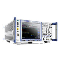
Rohde & Schwarz ESR-K56 User Manual (1081 pages)
EMI Test Receiver
Brand:
Rohde & Schwarz
| Category:
Receiver
| Size: 15 MB
Table of Contents
Table of Contents
3
Safety and Regulatory Information
19
Safety Instructions
19
Warning Messages in the Documentation
22
Korea Certification Class a
22
Documentation Overview
23
Getting Started Manual
23
User Manuals and Help
23
Service Manual
23
Instrument Security Procedures
24
Basic Safety Instructions
24
Data Sheets and Brochures
24
Release Notes and Open Source Acknowledgment (OSA)
24
Application Notes, Application Cards, White Papers, Etc
24
Conventions Used in the Documentation
25
Typographical Conventions
25
Conventions for Procedure Descriptions
25
Notes on Screenshots
25
The Front Panel
26
Instrument Tour
26
Touchscreen Display
27
Function Keys on the Front Panel
28
USB Interface
30
Noise Source Control
31
RF Input 50Ω
31
Probe Power
31
AF Output
31
Tracking Generator Output (Optional)
32
Rear Panel View
32
AC Power Supply Connection and Main Power Switch
33
Lan
33
VGA Interface
33
Ext Trigger / Gate in
33
Ref in
33
Ref out
33
Usb
34
AUX Port
34
IF / Video
34
Trigger Output
34
GPIB Interface
34
OCXO Option (R&S FSV-B4)
35
Device ID
35
Preparing for Use
36
Lifting and Carrying
36
Unpacking and Checking
36
Choosing the Operating Site
37
Placing the R&S ESR on a Bench Top
37
Setting up the R&S ESR
37
Setting up the R&SESR
37
Mounting the R&S ESR in a Rack
38
Connecting the AC Power
39
Connecting to a DC Power Source (Optional)
39
Switching the Instrument on and off
40
Connecting to LAN
41
Connecting a Keyboard
42
Connecting an External Monitor
42
Windows Operating System
43
Logging on
44
Checking the Supplied Options
46
Performing a Self Alignment and a Self Test
46
Considerations for Test Setup
47
Firmware Update
48
Firmware Update and Installation of Firmware Options
48
Activating Firmware Options
49
Basic Operations
51
Information in the Diagram Area
51
Channel Display
52
Display of Hardware Settings
53
Measurement Settings Information
54
Diagram-Specific and Trace Information
55
Instrument and Status Information
57
Means of User Interaction
58
Toolbar
59
Touchscreen
60
Keypad
61
On-Screen Keyboard
61
Rotary Knob
62
Arrow Keys, UNDO/REDO Keys
63
Softkeys
64
Context-Sensitive Menus
65
Dialog Boxes
66
Entering Alphanumeric Parameters
67
Entering Numeric Parameters
67
Setting Parameters
67
Navigating in Dialog Boxes
69
Changing the Display
72
Changing the Focus
72
Soft and Mini Soft Front Panel Display
72
Switching between Split and Maximized Display
72
Enlarging the Display Area
75
Displaying the Toolbar
76
Zooming into the Diagram
76
Adding a Title to the Diagram Header
78
Removing the Diagram Footer
78
Displaying and Setting the Date and Time
79
Selecting a Theme
79
Changing the Display Update Rate
80
Basic Measurement Examples
81
Measuring a Sinusoidal Signal
81
Measuring the Level and Frequency Using Markers
81
Increasing the Frequency Resolution
82
Setting the Reference Level
83
Measuring the Signal Frequency Using the Frequency Counter
84
Measuring Harmonics of Sinusoidal Signals
85
Measuring Signal Spectra with Multiple Signals
89
Separating Signals by Selecting the Resolution Bandwidth
89
Measuring the Modulation Depth of an AM-Modulated Carrier (Span > 0)
93
Measuring AM-Modulated Signals
94
Measurements in Zero Span
96
Measuring the Power Characteristic of Burst Signals
96
Measuring the Power of a GSM Burst During the Activation Phase
96
Measuring the Edges of a GSM Burst with High Time Resolution
98
Measuring the Signal-To-Noise Ratio of Burst Signals
100
Measuring FM-Modulated Signals
103
Storing an Instrument Configuration (Without Traces)
107
Storing and Loading Instrument Settings
107
Loading an Instrument Configuration (with Traces)
108
Storing Traces
108
Configuring Automatic Loading
109
Measurement Modes
110
Receiver Mode
110
Spectrum Mode
110
I/Q Analyzer Mode
111
Measurement Mode Root Menus (HOME Key)
111
Real Time Mode
111
Receiver Mode
112
Bargraph Measurement
112
Measurements and Result Displays
112
IF Spectrum Analysis
113
Scans
114
Stepped Scans in the Frequency Domain
115
The Scan Table
116
Time Domain Scans in the Frequency Domain
116
Peak List and Data Reduction
118
Scan on a Fixed Frequency
118
Final Measurement
120
How a Spectrogram Works
121
Spectrogram
121
Color Map
122
Measurement Control
126
Running Scans and Measurements
126
Selecting the Result Display
126
Bargraph Control
127
Scan Control
128
Final Measurement Control
130
Measurement Settings
132
Spectrogram Configuration
134
Measurement Basics
136
Measurement Bandwidth
136
Detectors
137
Trace Modes
141
AF Demodulation
142
V-Networks Control (LISN)
143
Transducers
145
Exported Peak List
146
Preamplifier
146
Formats for Returned Values: ASCII Format and Binary Format
147
Common Measurement Settings
149
Defining the Frequency and Span
149
Receiver Frequency
149
Stepsize
149
Full Span
150
IF Span Manual
150
Start / Stop Frequency
150
Configuring the Level Display and the RF Input
151
Last Span
151
Signal Track
151
Selecting the Bandwidth
154
Configuring the Scan
155
Configuring the Trigger
156
Controlling Inputs and Outputs
157
Overview
158
Test Automation
158
Scan Table
160
Peak Search
162
Peak Lists
164
LISN Settings
166
Trace / Final Meas
166
Common Analysis Functions
168
Trace Configuration
168
Controlling Markers
170
Markers
170
Positioning Markers
174
Markers in Spectrograms
177
Limit) Lines
178
Softkeys of the Lines Menu
179
Table of Contents
180
Copy to
181
Delete Value
181
Edit
181
Edit Margin
181
Edit Value
181
Insert Value
181
Save Limit Line
181
Delete
182
Display Line 1 / Display Line 2
182
Display Lines
182
Y Offset
182
Display Lines
183
Frequency Line 1 / Frequency Line 2
183
Time Line 1 / Time Line 2
183
Tuned Frequency (on Off)
183
Limit Lines (Frequency/Time Lines)
184
Selecting a Limit Line
185
Working with Lines
185
Creating a New Limit Line
186
Creating a New Limit Line Based Upon an Existing Limit Line
189
Editing an Existing Limit Line
189
Activating/Deactivating a Limit Line
190
Select Traces to Check
190
Measurements
191
Power Measurements - MEAS Key
191
Spectrum Measurements
191
Softkeys of the Power Measurement Menu
192
Measuring Channel Power and Adjacent-Channel Power
195
Table of Contents
205
Ch Power ACLR
206
CP/ACLR Standard
206
Channel Setup
207
CP/ACLR Settings
207
Of Adj Chan
207
Of TX Chan
207
Bandwidth
208
ACLR Reference
209
Spacing
209
Names
210
Weighting Filter
210
Limit Checking
211
Limits
211
Absolute Limit
212
Check
212
Relative Limit
212
Measuring the Carrier-To-Noise Ratio
219
Measuring the Occupied Bandwidth
222
Measuring with Spectrum Emission Masks
226
Table of Contents
227
Softkeys for Spectrum Emission Mask (SEM) Measurements Spectrum Emission Mask
228
Sweep └ Box
228
Filter Type
229
Range Start / Range Stop
229
Rbw
229
Factor
230
Mode
230
Preamp
230
Ref. Level
230
RF Att. Mode
230
RF Attenuator
230
Sweep Time
230
Vbw
230
Abs Limit Start
231
Abs Limit Stop
231
Limit Check 1-4
231
Rel Limit Start
231
Rel Limit Stop
231
Close Sweep List
232
Delete Range
232
Insert after Range
232
Insert before Range
232
Symmetric └ └ List Evaluation
233
ASCII File Export
234
List Evaluation (On/Off)
234
Save Evaluation List
234
Show Peaks
234
Edit Reference Range
235
Edit Power Classes
236
Pmin/Pmax
236
Used Power Classes
236
Add/Remove
237
Meas Start/Stop
237
Restore Standard Files
237
Save as Standard
237
Sweep
237
Format Description of Spectrum Emission Mask XML Files
245
ASCII File Export Format (Spectrum Emission Mask)
250
Fast Spectrum Emission Mask Measurements
251
Measuring Spurious Emissions
253
Measuring the Power in Zero Span
264
Performing EMI Measurements
267
CISPR APD Measurement (Amplitude Probability Distribution)
277
Calculating Signal Amplitude Statistics
282
Measuring the Third Order Intercept Point (TOI)
300
Measuring the am Modulation Depth
306
Measuring Harmonic Distortion
307
Configuration
311
Measurement Configuration - MEAS CONFIG Key
311
Performing Measurements - RUN SINGLE/RUN CONT Keys
311
Initial Configuration
312
Initializing the Configuration - PRESET Key
312
Presetting the Instrument
312
Selecting the Frequency and Span - FREQ Key
314
Softkeys of the Frequency Menu
314
Specifying the Frequency Axis by the Center Frequency and the Span
318
Specifying the Frequency Axis by the Start and Stop Frequency
318
Specifying the Step Size for the Arrow Keys and the Rotary Knob
318
Modifying the Frequency Axis by an Offset
319
Setting the Frequency Span - SPAN Key
319
Tracking Signals (Span > 0)
319
Softkeys of the Span Menu
320
Specifying the Span (Alternatives)
320
Setting the Level Display and Configuring the Rf Input - Ampt Key
321
Softkeys of the Amplitude Menu
321
Range
322
Range Log 10 Db
322
Range Log 100 Db
322
Range Log 50 Db
322
Ref Level
322
Range Linear
323
Range Log 1 Db
323
Range Log 5 Db
323
Range Log Manual
323
Preamp On/Off
324
Range Lin. Unit
324
Ref Level Offset
324
RF Atten Auto
324
Unit
324
Grid Abs/Rel
325
Ref Level Position
325
Defining Automatic Settings - AUTO SET Key
326
Softkeys of the Auto Set Menu
326
Specifying the Amplitude
326
Setting the Bandwidths and Sweep Time - Bw Key
330
Softkeys of the Bandwidth Menu
330
Res BW Auto
331
Res BW Manual
331
Video BW Manual
331
Sweeptime Manual
332
Video BW Auto
332
Auto
333
Fft
333
Sweep
333
Sweep Type
333
Sweeptime Auto
333
Auto
334
FFT Filter Mode
334
Narrow
334
Selecting the Appropriate Filter Type
336
Specifying the Bandwidth
336
List of Available RRC and Channel Filters
337
Configuring the Sweep Mode - SWEEP Key
339
Softkeys of the Sweep Menu
339
Softkeys of the Trigger Menu
344
Specifying the Sweep Settings
344
Triggering the Sweep - TRIG Key
344
Specifying the Trigger Settings
351
Using Gated Sweep Operation
351
Input/Output Configuration - INPUT/OUTPUT Key
353
Softkeys of the Input/Output Menu
353
Using Active Probes for Input
355
Analysis
357
Softkeys of the Trace Menu
358
Trace Configuration
358
Configuring Traces
365
Description of the Averaging Method
367
Specifying the Trace Settings
367
ASCII File Export Format
369
Detector Overview
369
Spectrogram
372
Working with Spectrograms
372
Softkeys of the Spectrogram Menu
375
Controlling Markers
376
Markers
376
Positioning Markers (MKR➙ Key)
381
Performing Peak Searches with Markers - PEAK SEARCH Key
385
Measuring with Markers (MKR FUNC Key)
386
Lines
399
Advanced Measurement Examples
400
Test Setup
400
Measurement of Harmonics
401
Measuring the Spectra of Complex Signals
403
Separating Signals by Selecting an Appropriate Resolution Bandwidth
403
Intermodulation Measurements
404
Measuring Signals in the Vicinity of Noise
406
Measurement Example - Measuring Level at Low S/N Ratios
407
Noise Measurements
411
Measuring Noise Power Density
412
Measurement of Noise Power Within a Transmission Channel
414
Measuring Phase Noise
416
Measurements on Modulated Signals
418
Measuring Channel Power and Adjacent Channel Power
418
Amplitude Distribution Measurements
425
Q Analyzer
428
Softkeys and Parameters of the I/Q Analyzer Menu
429
Softkeys of the Amplitude Menu in I/Q Analyzer Mode
434
Softkeys of the Marker to Menu in I/Q Analyzer Mode
439
Softkeys of the Trigger Menu in I/Q Analyzer Mode
439
Working with I/Q Data
443
Sample Rate and Maximum Usable Bandwidth (RF Input)
444
Softkeys of the Tracking Generator Menu
446
Tracking Generator
446
Connecting External Tracking Generators
451
Overview of Generators Supported by the R&S ESR
452
Configuring Tracking Generators
455
Internal Tracking Generator
455
External Tracking Generator
457
Calibration Mechanism
462
Tracking Generator Functions
462
Calibrating for Transmission and Reflection Measurement
463
Normalization
464
Reflection Measurement
464
Transmission Measurement
464
Modulation (Internal Tracking Generator Only)
468
Displayed Information and Errors
470
Manual Operation - Local Menu
472
System Configuration
472
User-Defined Menu - USER Key
473
Instrument Setup and Interface Configuration - SETUP Key
474
Softkeys of the Setup Menu
475
Data Management and Documentation
499
Saving and Recalling Settings Files - SAVE/RCL Key
499
Softkeys of the SAVE/RCL Menu
500
File Selection Dialog Boxes
506
Importing and Exporting I/Q Data
508
Iq-Tar File Format Specification
508
Measurement Documentation - PRINT Key
513
Designing a Test Report Template
517
Working with Test Reports
517
Creating a Test Report
521
Remote Control
524
Remote Control - Basics
524
Remote Control Interfaces and Protocols
524
Messages
526
VISA Libraries
526
LAN Interface
527
GPIB Interface (IEC 625/IEEE 418 Bus Interface)
530
Starting a Remote Control Session
534
Returning to Manual Operation
535
SCPI Command Structure
535
Syntax for Common Commands
535
Syntax for Instrument-Specific Commands
536
SCPI Parameters
537
Overview of Syntax Elements
540
Structure of a Command Line
541
Responses to Queries
542
Command Sequence and Synchronization
543
Preventing Overlapping Execution
544
Hierarchy of Status Registers
546
Status Reporting System
546
Structure of a SCPI Status Register
546
Contents of the Status Register
548
Application of the Status Reporting System
560
Reset Values of the Status Reporting System
562
General Programming Recommendations
563
The IECWIN Tool
563
Controlling the R&S ESR Remotely
565
Setting up Windows Remote Desktop
565
Configuring the R&S ESR for Remote Operation
566
Configuring the Controller
567
Starting and Terminating Remote Operation
569
Deactivating the R&S ESR Via Remote Operation
571
Setting up a VNC Client
571
Configuring the GPIB Interface
572
Connecting the Instrument to the Network
573
Setting up a Network (LAN) Connection
573
Assigning the IP Address
574
Using Computer Names
577
Changing the Windows Firewall Settings
578
How to Configure the LAN Using the Web Browser Interface
578
LAN Configuration
579
Configuring the Network
580
Changing the User Password
581
Creating Users
581
Operating the Instrument Without a Network
581
Mapping Network Drives
582
Sharing Directories (Only with Microsoft Networks)
583
Basic Steps in Remote Control Programming
584
Brief Introduction to Remote Control
584
Detailed Programming Examples
591
Selecting the Operating Mode
603
Display Configuration
605
Measurements and Result Displays
605
Remote Commands in Receiver Mode
605
Bargraph Control
606
Scan Control
608
Final Measurements and Automated Test Sequence Control
610
Trace Data and Result Query
612
Demodulating Analog Signals
616
Fixed Frequency Scans
616
Spectrogram Control
618
Defining the Frequency
633
Configuring the Vertical Axis
636
Selecting the Bandwidth
639
Controlling Inputs and Outputs
641
Test Automation
641
General Scan Configuration
642
Scan Table
643
Peak Search
647
Peak Lists
650
Trace Configuration
651
LISN Settings
653
Configuring Marker Functionality
656
Working with Markers
656
Using Markers
660
Using Delta Markers
665
Limit Lines
672
Using Display Lines
672
Using Frequency Lines
673
Using Limit Lines
674
Controlling Power Measurements
688
Measurements and Result Displays
688
Remote Commands in Spectrum Analyzer Mode
688
Measuring Channel Power
695
Measuring the Occupied Bandwidth
716
Measuring Spurious Emissions
717
Testing against a Spectrum Emission Mask
728
Performing EMI Measurements
747
Measuring the Modulation Depth
753
Measuring the Harmonic Distortion
755
Measuring the Carrier-To-Noise Ratio
759
Measuring the Third Order Intercept Point
759
Measuring Statistics
760
Measuring in the Time Domain
768
Measuring the Pulse Power
780
Performing List Evaluations
784
Probe Configuration
789
Configuring Spectrum Measurements
791
Frequency Settings
791
Automatic Measurement Configuration
796
Bandwidth Settings
799
Sweep Configuration
802
Trigger Configuration
805
Vertical Axis Configuration
812
Analyzing Spectrum Measurements
816
Trace Configuration
816
Spectrogram
825
Limit Lines
829
Markers
830
Remote Commands in I/Q Analyzer Mode
856
Using the I/Q Analyzer
856
I/Q Gating
868
Controlling the Internal Tracking Generator
869
Remote Commands to Control the Tracking Generator
869
Controlling the External Tracking Generator
876
Common Commands
884
General System Configuration
888
System Configuration
888
Checking the System Configuration
893
Coupling Parameters
896
Controlling In- and Ouputs
900
Configuring the Reference Frequency
903
Calibrating the R&S ESR
904
Using Service Functions
907
Data Management
909
Managing Data Files
909
Saving and Restoring Customized Data
915
Using Transducers
919
Documentation
926
Designing a Test Report Template
935
Selecting the Test Report Contents
935
Working with Test Reports
935
Designing the Header of the Test Report
938
Defining the Contents of the Title Page
940
Managing Templates
941
Configuring and Printing the Test Report
942
Creating a Test Report
942
Adding and Removing Datasets
943
Selecting Datasets for the Report
944
Deprecated Commands (Test Report)
945
Controlling Display Elements
946
Display Configuration
946
Selecting Items to Store and Restore
954
Configuring Network Connections
956
Network Connection
956
Emulating HP Instruments
960
Status Register
963
General Status Register Commands
964
Reading out the Event Part
964
Controlling the Enable Part
965
Reading out the Condition Part
965
Controlling the Negative Transition Part
966
Controlling the Positive Transition Part
966
Remote Control - Programming Examples
967
Initiate Service Request
968
Service Request
968
Waiting for the Arrival of a Service Request
970
Service Request Routine
972
Waiting Without Blocking the Keyboard and Mouse
972
Reading out the Output Buffer
973
Evaluation of SCPI Status Registers
974
Reading Error Messages
974
Evaluation of Event Status Register
975
Shape Factor Measurement (Using N Db Down)
976
Using Marker and Delta Marker
976
Measuring the Third Order Intercept Point
977
Measuring the am Modulation Depth
978
Limit Lines and Limit Test
979
Measuring the Channel and Adjacent Channel Power
981
Occupied Bandwidth Measurement
984
Fast Power Measurement on Power Ramps
985
Time Domain Power Measurement
985
Power Measurement with Multi-Summary Marker
986
Multi-Burst Power Measurement
987
Fast Level Measurement Using Frequency Lists
989
Level Correction of Transducers
991
Measuring the Magnitude and Phase of a Signal
992
Creating a File on the Instrument
994
Reading a File from the Instrument
994
Reading and Writing Files
994
Spectrum Emission Mask Measurement
995
Using Predefined Standard Wibro
995
Defining 5 Ranges with All Parameters
996
Spurious Emissions Measurement
999
Averaging I/Q Data
1002
Using IQ Gating
1003
Usage of Four Spectrum Instances
1008
GPIB Commands of HP Models 856Xe, 8566A/B, 8568A/B and 8594E
1010
GPIB Languages
1010
Command Set of Models 8560E, 8561E, 8562E, 8563E, 8564E, 8565E, 8566A/B, 8568A/B, 8591E, 8594E, 71100C, 71200C, and 71209A
1012
Special Features of the Syntax Parsing Algorithms for 8566A and 8568A Models
1035
Special Behavior of Commands
1036
Model-Dependent Default Settings
1037
Data Output Formats
1038
GPIB Status Reporting
1038
Trace Data Input Formats
1038
Trace Data Output Formats
1038
Error Information
1040
Troubleshooting
1040
Error Messages
1041
Collecting Information for Support
1042
Contacting Customer Support
1043
Transporting
1045
Changing Fuses
1046
Cleaning
1046
Maintenance, Storage, Transport and Disposal
1046
Storage
1046
Disposal
1047
List of Commands
1048
Index
1065
Advertisement
Advertisement
Related Products
Rohde & Schwarz ESRP EMI
Rohde & Schwarz ESRP3 EMI
Rohde & Schwarz ESRP7 EMI
Rohde & Schwarz ESRP3 EMV
Rohde & Schwarz ESRP7 EMV
Rohde & Schwarz ESR3
Rohde & Schwarz ESR7
Rohde & Schwarz ESR26
Rohde & Schwarz ESR-B50
Rohde & Schwarz ESR-K53
Rohde & Schwarz Categories
Measuring Instruments
Test Equipment
Portable Generator
Power Supply
Accessories
More Rohde & Schwarz Manuals
Login
Sign In
OR
Sign in with Facebook
Sign in with Google
Upload manual
Upload from disk
Upload from URL