Sign In
Upload
Manuals
Brands
Rohde & Schwarz Manuals
Test Equipment
CRTU-RU
Rohde & Schwarz CRTU-RU Manuals
Manuals and User Guides for Rohde & Schwarz CRTU-RU. We have
2
Rohde & Schwarz CRTU-RU manuals available for free PDF download: Service Manual, Operating Manual
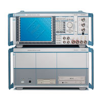
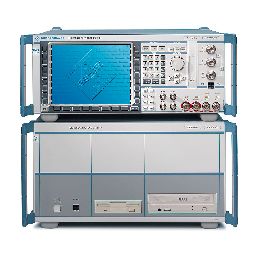
Rohde & Schwarz CRTU-RU Service Manual (213 pages)
Radio Unit
Brand:
Rohde & Schwarz
| Category:
Test Equipment
| Size: 4 MB
Table of Contents
Table of Contents
5
Performance Test
19
Performance Test
21
Test Options
21
Necessary Documents
21
List of Figures
23
Measuring Instruments and Auxiliary Equipment
22
Fig. 1-1 Test Setups for Reference Frequencies
23
Reference Frequencies
23
Test Setups
23
TX Level Measurements
23
Fig. 1-2 Test Setups for TX Level Measurements
24
Fig. 1-3 Test Setups for General TX Measurements
24
General TX Measurements
24
Fig. 1-4 Test Setups for RX Level Measurements
25
Fig. 1-5 Test Setups for General RX Measurements
25
General RX Measurements
25
RX Level Measurements
25
Fig. 1-6 Test Setups for RX Demodulation Measurements
26
RX Demodulation Measurements
26
Tolerance Analysis
26
Manual Test Procedure
27
Selftest
27
Control and Sync Bus (CSB) and Trigger Test of CRTU
28
IEC-Bus Interface
28
Interface Test
28
RS-232 Interface
28
Ref
32
Reference Frequencies
32
Ref out 1
33
TX Frequency Accuracy
33
TX Frequency Settling Time
33
TX Harmonics
34
TX Level Error
34
TX Level Settling Time
34
Vswr
34
TX Fixed Spurious Signals
35
TX In-Band Spurious Signals
35
TX Non Harmonics
35
TX SSB Phase Noise
35
RX Power Meter (Frequency-Selective)
36
TX Carrier/Sideband Suppression, Max. Distortion
36
TX Residual
36
RX Harmonics
37
RX Power Meter (Wideband)
37
RX Spurious Response / Image Rejection
37
RX Dynamic/ Average Noise Level
38
RX Residual FM
38
RX SSB Phase Noise
38
Options for CRTU Radio Unit
39
RX GSM Demodulation
39
TX GSM Modulation
39
Hardware Test of CRTU-B5 and CRTU-B6
40
RF Loopback Overall Test
40
Verification of GSM Functionality
40
Real Mobile Overall Test
41
Detection Test of CRTU-G or CRTU
42
EDGE Layer 1 Performance Tool Test
42
Tables
54
Test Reports
43
Table 1-2 Test Report
54
Table 1-3 Test Report GSM Functionality
63
Adjustment
65
Adjustment
67
Manual Adjustment
67
Measuring Instruments and Auxiliary Equipment
67
Adjusting the + 5 VDC Reference Voltage
68
Adjusting the 10 Mhz Reference Frequency
68
Preparing the Instrument
68
Ocxo Reference Osc. Crtu-B2
69
Tcxo
69
Automatic Adjustment of Module Data
70
Performing the Adjustment
70
Preparing the Adjustment
70
Table 2-1 Measuring Instruments and Auxiliary Equipment for Manual Adjustment of the CRTU Radio Unit
67
Repair
71
Instrument Design and Function Description
75
Repair
75
Block Diagram
76
Front of Instrument Frame
77
Instrument Frame
77
Rear of Instrument Frame
77
Cooling the Instrument
78
Front Module
79
Power Supply
80
Motherboard
81
Reference Board
82
Option OCXO REFERENCE OSC. CRTU-B2
83
Rf Frontend
83
Rxtx Board1/2
84
Digital Board
86
Complete Function
87
Control and Supply
87
Cooling System
87
Option LINKHANDLER1/2 CRTU-B5
87
Audio Function
88
Control and Supply
88
Cooling System
88
DSP 56301 Modules
88
DSP 56311 Modules
88
MAC/RLC Function
88
Option MAC SPEECH CRTU-B6
88
Receiver Function
88
Transmitter Function
88
DSP 56301 Module
89
Option IQIF BOARD CRTU-B7
89
Module Replacement
91
Opening the Instrument and Removing the FRONT MODULE
91
Replacing the FRONT MODULE
91
Installing the New FRONT MODULE and Completing the Instrument
92
Putting into Operation
92
Opening the Instrument and Removing the FRONT MODULE
93
Removing the FRONT MODULE CONTROLLER from the FRONT MODULE
93
Replacing the FRONT MODULE CONTROLLER in the FRONT MODULE
93
Installing the New FRONT MODULE CONTROLLER
94
Installing the Option Again and Completing the Instruments
94
Putting into Operation, BIOS Update
94
Opening the Instrument and Removing the FRONT MODULE
95
Removing the Lithium Battery
95
Replacing the Lithium Battery in the FRONT MODULE
95
Installing the New Battery and Completing the Instrument
96
Putting into Operation
96
Installing the New Hard Disk
97
Opening the Instrument and Removing the FRONT MODULE
97
Putting into Operation
97
Removing the Hard Disk from the FRONT MODULE
97
Replacing the Hard Disk in the FRONT MODULE
97
Saving Customer-Specific Data
97
Customizing the Hard Disk
98
Installing the GSM Operational Software
99
Cleaning up the System
100
Opening the Instrument and Removing the FRONT MODULE
100
Replacing the Memory Modules in the FRONT MODULE
100
Installing the New Memory Module and Completing the Instrument
101
Making the Memory Modules Accessible
101
Putting into Operation
101
Removing the Memory Module
101
Making the LCD Accessible
102
Opening the Instrument and Removing the FRONT MODULE
102
Replacing the LCD And/Or DC/AC Converter in the FRONT MODULE
102
Installing the New LCD And/Or DC/AC Converter and Completing the Instrument
103
Putting into Operation
103
Removing the LCD And/Or DC/AC Converter
103
Opening the Instrument and Removing the FRONT MODULE
104
Removing the Membrane
104
Replacing the Keyboard Membrane And/Or Mat on the FRONT MODULE
104
Installing the New Labeling Panel and Completing the Instrument
105
Installing the New Membrane and Completing the Instrument
105
Putting into Operation
105
Removing the Old Labeling Panel
105
Replacing the Labeling Panel on the FRONT MODULE
105
Completing the Instrument and Putting into Operation
106
Opening the Instrument and Removing the FRONT MODULE
106
Replacing the Option
106
Replacing the PCMCIA INTERFACE
106
Automatic Module Data Adjustment
107
Installing the New RF FRONTEND MODULE and Completing the Instrument
107
Opening the Instrument and Removing the RF FRONTEND
107
Replacing the RF FRONTEND
107
Automatic Module Data Adjustment
108
Installing the New REFERENCE BOARD and Completing the Instrument
108
Opening the Instrument and Removing the REFERENCE BOARD
108
Replacing the REFERENCE BOARD
108
Automatic Module Data Adjustment
109
Installing the New RXTX BOARD1/2 and Completing the Instrument
109
Opening the Instrument and Removing the RXTX BOARD1/2
109
Replacing the RXTX BOARD1/2
109
Automatic Module Data Adjustment
110
Installing the New TR-CORRECTION BOARD and Completing the Instrument
110
Opening the Instrument and Removing the TR-CORRECTION MODULE
110
Replacing the TR-CORRECTION MODULE in the RXTX BOARD1/2
110
Automatic Module Data Adjustment
111
Installing the New DIGITAL BOARD and Completing the Instrument
111
Opening the Instrument and Removing the DIGITAL BOARD
111
Replacing the DIGITAL BOARD
111
Installing the New Sandwich Module and Completing the Instrument
113
Opening the Instrument and Removing the Modules
113
Replacing the Modules: ADC MODULE1/2, DDC MODULE1/2, TXDSP MODULE1/2, AUC MODULE1/2 in the DIGITAL BOARD
113
Automatic Module Data Adjustment
114
Installing the New Option OCXO REFERENCE OSC. and Completing the Instrument.3.41
115
Manual OCXO Adjustment
115
Opening the Instrument and Removing the Option OCXO REFERENCE OSC
115
Replacing the Option OCXO REFERENCE OSC. CRTU-B2
115
Automatic Module Data Adjustment
116
Installing the New Option LINKHANDLER 1/2 and Completing the Instrument
116
Opening the Instrument and Removing the Option LINKHANDLER 1/2
116
Replacing the Option LINKHANDLER 1/2 CRTU-B5
116
Automatic Module Data Adjustment
117
Installing the New Sandwich Module and Completing the Instrument
117
Opening the Instrument and Removing the Modules
117
Replacing the Modules: DSP MODULE0/1/2/3/4/5 in the LINKHANDLER 1/2
117
Automatic Module Data Adjustment
119
Installing the New Option MAC SPEECH and Completing the Instrument
119
Opening the Instrument and Removing the Option MAC SPEECH
119
Replacing the Option MAC SPEECH CRTU-B6
119
Installing the New Sandwich Module and Completing the Instrument
120
Opening the Instrument and Removing the Modules
120
Replacing the Modules: DSP MODULE in the MAC SPEECH
120
Automatic Module Data Adjustment
121
Installing the New Option IQIF BOARD and Completing the Instrument
121
Opening the Instrument and Removing the Option IQIF BOARD
121
Replacing the Option IQIF BOARD CRTU-B7
121
Installing the New Fan and Completing the Instrument
122
Installing the New POWER SUPPLY
122
Opening the Instrument and Removing the Fan
122
Removing the POWER SUPPLY
122
Replacing the Instrument Fan
122
Replacing the POWER SUPPLY
122
MOTHERBOARD1 (Big MOTHERBOARD)
123
Replacing the MOTHERBOARD
123
FRONTPANEL BOARD1 (at the Front of the Instrument Frame)
124
MOTHERBOARD2 (Small MOTHERBOARD)
124
FRONTPANEL BOARD2 (at the Front of the Instrument Frame)
125
REARPANEL BOARD (Interface Board for Further Connectors at the Rear of the Instrument Frame)
125
Troubleshooting
126
Troubleshooting Using the Leds (H1 to H9) on the MOTHERBOARD
127
Troubleshooting Using the SELFTEST Menu for Modules
129
Troubleshooting Using the INFO Menu for Modules
130
Motherboard Test CRTU-RU and CRTU
132
Troubleshooting Using the ERROR Messages on the LC Display
132
General Errors on the Transmitter Side of the CRTU Radio Unit
133
More Troubleshooting
133
General Errors on the Receiver Side of the CRTU Radio Unit
134
Software Update/Installing Options
135
Structures of Hard Disk Partitions
137
Detection of Different Hard Disk Structures
137
Software Update/Installing Options
137
Software / Firmware Structure
137
Fig. 4-1 "New" Vs. "Old" Partition Structure on the CRTU-RU Hard Disk
138
Old" Partition Structure
138
Fig. 4-2 Drive Mapping after Booting the GSM Operation Software (Old Partition Structure)
139
Table 4-1 Software Packages, Boot Partitions and Hard Disk Partitions
139
New" Partition Structure
139
Fig. 4-3 Drive Mapping after Booting the Windows OPSW (New Partition Structure)
140
Maintaining and Restoring Hard Disk Partitions
141
Creating User-Specific Images
142
Images Provided Ex Factory (\Stdimage)
142
Restoring Existing Images
142
Table 4-3 Images and Image Files
142
Updating Factory Images
142
Table 4-2 Software Packages, Boot Partitions and Hard Disk Partitions
141
Front Module Controller Bios
143
Front Module Controller Bios Update
143
Fig. 4-4 Versionmanager
144
CRTU-RU MS Software
144
CRTU-RU MS Software Installation or Update
144
Reinstalling Old Software
145
Installing Hardware Options
146
Documents
147
Documents
149
Module and Cable Exchange
149
Table 5-1 List of Power Cables Available
150
List of Spare Parts for CRTU Radio Unit
153
Drawings
161
Advertisement
Rohde & Schwarz CRTU-RU Operating Manual (37 pages)
Radio Unit
Brand:
Rohde & Schwarz
| Category:
Radio
| Size: 1 MB
Table of Contents
Table of Contents
3
Preparations for Use
5
CRTU-RU - Preparation for Use
5
Front View
6
Fig. 1-2 CRTU-RU Front View- Connectors
7
Fig. 1-3 CRTU-RU Front View- Connectors
8
PCMCIA Interface
8
Fig. 1-4 CRTU-RU Front View- Connectors
9
USB Connectors
9
AUX Connectors
9
Rear View
10
Fig. 1-5 CRTU-RU Rear View
10
Fig. 1-6 CRTU-RU Rear View
11
Mains Switch
11
Fig. 1-7 CRTU-RU Rear View
12
Fig. 1-8 CRTU-RU Rear View
14
Fig. 1-9 CRTU-RU Rear View
14
Putting the Instrument into Operation
15
Unpacking the Instrument
15
Setting up the Instrument
15
Mounting in a Rack
16
Connecting the Instrument to the AC Supply
16
Mains Connector
16
Switching on the Instrument / Startup Test
17
On/Standby Key
17
Start Procedure
17
Fig. 1-10 Bootmagic Startup Screen
18
Software Selection
18
Fig. 1-11 Bootmagic Startup Menu
18
Switching off the Instrument
19
How to Ensure EMC
19
PCMCIA Card Connection
19
Input Level
19
Connecting the Instrument to the Test Setup
20
Connecting a Printer
20
Test Setup for Multi Device Mode
20
Synchronization with External Devices
21
Connection of Further Components
22
GPIB Bus
22
Software Update / Software Codes
23
Tools
24
Maintenance and Interfaces
25
Maintenance
25
Cleaning the Outside
25
Storing and Packing
25
Hardware Interfaces
26
GPIB Bus Interface
26
Characteristics of the Interface
26
Bus Lines
26
Fig. 2-1 Pin Assignment of the GPIB Bus Interface
26
Interface Messages
27
RS232 Interfaces (COM 1, COM 2)
28
Interface Characteristics
28
Signal Lines
28
Fig. 2-2 Pin Assignment of the Serial Interface
28
Connectors for Peripherals
30
LPT Interface
30
Fig. 2-3 Pin Assignment of the LPT Connector
30
Monitor Connector (MONITOR)
31
USB Connectors
31
Fig. 2-4 Pin Assignment of the MONITOR Connector
31
Fig. 2-5 USB Connector
31
PS/2 Connector (PS/2)
32
Signal Inputs and Outputs
32
RF Connectors
32
Fig. 2-6 Pin Assignment of the PS/2 Socket
32
Inputs and Outputs for the Reference Frequency (REF
33
Trigger Signals
33
Clock Signals
33
Control Sync/Pu
33
IF Signal Monitoring (Only with Option B7)
33
IF Signal PU (Only with Option B7)
33
Data Ch1/Ch2, Ctrl Ch1/Ch2 Led
34
Iq In/Out Ch1/Ch2
34
Auxiliary Connector
34
Fig. 2-7 DATA CH1/CH2 Connector
34
Fig. 2-8 IQ IN/OUT CH1/CH2 Connector
34
Fig. 2-9 aux Connector
34
Ethernet Connector
35
Fig. 2-10 Ethernet Connector
35
Index
37
Advertisement
Related Products
Rohde & Schwarz R&S CMW-KM200
Rohde & Schwarz CMW-KS8 Series
Rohde & Schwarz CMW-KS880
Rohde & Schwarz R&S CMW-KM70 Series
Rohde & Schwarz R&S CMW-KM700
Rohde & Schwarz R&S CMW-KS701
Rohde & Schwarz R&S CMW-KA700
Rohde & Schwarz R&S CMW-KT700
Rohde & Schwarz R&S CMW-KS702
Rohde & Schwarz CTS50
Rohde & Schwarz Categories
Measuring Instruments
Test Equipment
Portable Generator
Power Supply
Accessories
More Rohde & Schwarz Manuals
Login
Sign In
OR
Sign in with Facebook
Sign in with Google
Upload manual
Upload from disk
Upload from URL