Sign In
Upload
Manuals
Brands
Rockwell Automation Manuals
Adapter
PowerFlex 755 Drive
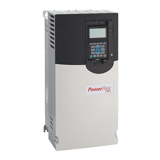
Rockwell Automation PowerFlex 755 Drive Manuals
Manuals and User Guides for Rockwell Automation PowerFlex 755 Drive. We have
1
Rockwell Automation PowerFlex 755 Drive manual available for free PDF download: User Manual
Rockwell Automation PowerFlex 755 Drive User Manual (233 pages)
Embedded EtherNet/IP Adapter
Brand:
Rockwell Automation
| Category:
Adapter
| Size: 10 MB
Table of Contents
Important User Information
2
Summary of Changes
3
Table of Contents
5
Preface
9
Related Documentation
9
Conventions Used in this Manual
10
Rockwell Automation Support
10
About this Manual
9
Chapter 1 Getting Started
11
Components
11
Getting Started
11
Features
12
Compatible Products
13
Required Equipment
13
Safety Precautions
14
Quick Start
15
Status Indicators
16
Chapter 2 Installing the Adapter
17
Installing the Adapter
17
Preparing for an Installation
17
Setting the IP Address Switches
18
Applying Power
20
Connecting the Adapter to the Network
20
Drive and Adapter Start-Up Status Indications
21
Start-Up Status Indications
21
Commissioning the Adapter
22
Configuring/Verifying Key Drive Parameters
22
Chapter 3 Configuring the Adapter
23
Configuration Tools
23
Configuring the Adapter
23
Using the Enhanced Powerflex 7-Class HIM
23
Configuring the Adapter Using BOOTP Server
24
Using BOOTP
24
BOOTP Server Window
25
Accessing Parameters in the Adapter
27
Disabling the BOOTP Feature
27
Setting an IP Address Using Parameters
27
Setting the IP Address, Subnet Mask, and Gateway Address
27
Edit IP Addr Cfg 1 HIM Screen
28
Setting a Gateway Address for the Adapter Using Parameters
28
Setting a Subnet Mask Using Parameters
28
Edit Gateway Cfg 1 HIM Screen
29
Setting the Data Rate
29
Selecting Master-Slave or Peer-To-Peer
30
Setting a Master-Slave Hierarchy
30
Setting the Adapter to Transmit Peer-To-Peer Data
32
Edit to Peer Enable HIM Screen
33
Edit Fr Peer Timeout HIM Screen
34
Edit Fr Peer Addr 1 Screen on the HIM
35
Edit Fr Peer Enable HIM Screen
35
Edit Peer Flt Action HIM Screen
35
Changing the Fault Action
36
Setting a Fault Action
36
Edit Fault Action HIM Screens
37
Setting the Fault Configuration Parameters
37
Edit Web Enable HIM Screen
38
Edit Web Features HIM Screen
38
Setting Web Access Control
38
Restoring Adapter Parameters to Factory Defaults
39
Flash Updating the Adapter
40
Viewing the Adapter Status Using Parameters
40
Chapter 4 Configuring the I/O
41
Configure Drivers Screen with a Configured Driver
41
Using Rslinx Classic
41
Controllogix Example
42
Bridge Select Module Screen
43
New Controller Screen (Rslogix 5000 V16 Shown)
43
Bridge New Module Screen
44
Rslogix 5000: I/O Configuration Folder
44
Drive Select Module Screen
45
Using Rslogix 5000 Add-On Drive Profiles (V16 or Higher)
45
Drive New Module Screen
46
Module Definition Screen
46
Example Datalink Parameter Properties Screen
48
Connection Screen
49
Port Configuration Screen
49
Controller Input Tags
51
Controller Output Tags
52
Download Dialog Box
52
Differences Found Screen
54
Drive Correlation Screen
54
I/O Configuration Differences Screen
54
Select Module Screen
55
Input Image Controller Tags
58
Output Image Controller Tags
58
Limitations When Using PLC-5, SLC 500, and Micrologix 1100
60
Configuring Parameters for Network I/O
61
PLC-5 Example
61
PLC-5 Example Ethernet/Ip Network
61
Adapter Parameter Settings for PLC-5 Example
62
Creating Rslogix 5 (V7 or Higher) Project
63
PLC-5 Select Processor Type Screen
63
PLC-5 Ladder Logic for the Control Timeout
64
PLC-5 Message Configuration Screens for the Control Timeout
64
PLC-5 Message Configuration Screens for the Logic Status Feedback, and DL from Net Datalinks
66
PLC-5 Ladder Logic for the Logic Command, Reference, and DL to Net Datalinks
67
PLC-5 Message Configuration Screens for the Logic Command, Reference, and DL to Net Datalinks
68
SLC 500 Example
69
SLC 500 Example Ethernet/Ip Network
69
Adapter Parameter Settings for SLC 500 Example
70
Creating Rslogix 500 (V7 or Higher) Project
70
SLC 500 Select Processor Type Screen
71
SLC 500 Ladder Logic for the Control Timeout
72
SLC 500 Message Configuration Screens for the Control Timeout
72
SLC 500 Ladder Logic for the Logic Status, Feedback, and DL from Net Datalinks
73
SLC 500 Message Configuration Screens for the Logic Status, Feedback, and DL from Net Datalinks
74
SLC 500 Ladder Logic for the Logic Command, Reference, and DL to Net Datalinks
75
SLC 500 Message Configuration Screens for the Logic Command, Reference, and DL to Net Datalinks
76
Micrologix 1100 Example
77
Micrologix 1100 Example Ethernet/Ip Network
77
Adapter Parameter Settings for Micrologix 1100 Example
78
Micrologix 1100 Select Processor Type Screen
79
Micrologix 1100 Ladder Logic for the Control Timeout
80
Micrologix 1100 Message Configuration Screens for the Control Timeout
80
Micrologix 1100 Ladder Logic for the Logic Status, Feedback, and DL from Net Datalinks
81
Micrologix 1100 Message Configuration Screens for the Logic Status, Feedback, and DL from Net Datalinks
82
Micrologix 1100 Ladder Logic for the Logic Command, Reference, and DL to Net Datalinks
83
Micrologix 1100 Message Configuration Screens for the Logic Command, Reference, and DL to Net Datalinks
84
About I/O Messaging
85
Chapter 5 Using the I/O
85
Using the I/O
85
Controllogix Controller Image
86
Controllogix I/O Image for Powerflex 750-Series Drives
86
Understanding the I/O Image
86
PLC-5, SLC 500, and Micrologix 1100 Controller Image
87
PLC-5, SLC 500, and Micrologix 1100 I/O Image for Powerflex 750-Series Drives
87
Using Logic Command/Status
88
Using Reference/Feedback
88
Example Speed Reference/Feedback Scaling for Powerflex 750-Series Drives
89
Using Datalinks
89
Controllogix Example
90
Example Ladder Logic Program Information
90
Controllogix Example Ladder Logic Program Using Add-On Drive Profiles for Logic Status/Feedback
91
Controllogix Program Tags for Integrated Drive Profile Ladder Logic Program Example
91
Controllogix Example Ladder Logic Program Using Add-On Drive Profiles for Logic Command/Reference
92
Creating Ladder Logic Using the Rslogix 5000 Generic Profile (All Versions)
92
Controllogix Controller Tags for Generic Drive Profile Example Ladder Logic Program
93
Controllogix Input Image for Generic Drive Profile Example Ladder Logic Program
94
Controllogix Output Image for Generic Drive Profile Example Ladder Logic Program
94
Controllogix Example Ladder Logic Program Using Generic Drive Profiles for Logic Status/Feedback
95
Controllogix Program Tags for Generic Drive Profile Example Ladder Logic Program
95
Controllogix Example Ladder Logic Program Using Generic Drive Profiles for Logic Command/Reference
96
Controllogix Example Datalinks for Ladder Logic Program Using Generic Drive Profile
97
Adapter Parameter Settings
98
Data File Table for Example Ladder Logic Program
98
PLC-5, SLC 500, and Micrologix 1100 Example
98
Understanding Controller Data Table Addresses
98
PLC-5, SLC 500, and Micrologix 1100 Data Table Addresses for Powerflex 750-Series Drives
99
Controller and Program Data Table Address Descriptions for Example Logic Status/Feedback Ladder Logic Program
100
PLC-5, SLC 500, and Micrologix 1100 Example Ladder Logic Program for Logic Status/Feedback
101
Program and Controller Data Table Address Descriptions for Example Logic Command/Reference Ladder Logic Program
101
PLC-5, SLC 500, and Micrologix 1100 Example Ladder Logic Program for Logic Command/Reference
102
About Explicit Messaging
103
Chapter 6 Using Explicit Messaging
103
Using Explicit Messaging
103
Performing Explicit Messages
104
Controllogix Example Ladder Logic Program to Read Single Parameter
105
Example Controller Tags for Read Single Parameter Messaging Program
105
Example Ladder Logic Explicit Messaging Program for Read Single
105
Controllogix – Formatting a Message to Read Single Parameter
106
Get Attribute Single Message Configuration Screens
106
Controllogix Example Ladder Logic Program to Write Single Parameter
107
Example Controller Tags for Write Single Parameter Messaging Program
107
Example Ladder Logic Explicit Messaging Program for Write Single
107
Controllogix – Formatting a Message to Write Single Parameter
108
Set Attribute Single Message Configuration Screens
108
Controllogix Example Ladder Logic Program to Read Multiple Parameters
109
Example Controller Tags for Read Multiple Parameter Messaging Program
109
Example Ladder Logic Explicit Messaging Program for Read Multiple
109
Controllogix – Formatting a Message to Read Multiple Parameters
110
Scattered Read Message Configuration Screens
110
Example Scattered Read Request Data
111
Example Scattered Read Response Converted Data
111
Controllogix Example Ladder Logic Program to Write Multiple Parameters
112
Example Controller Tags for Write Multiple Parameter Messaging Program
112
Example Ladder Logic Explicit Messaging Program for Write Multiple
112
Controllogix – Formatting a Message to Write Multiple Parameters
113
Scattered Write Multiple Message Configuration Screens
113
Example Scattered Write Request Converted Data
114
Example Scattered Write Response Data
114
Controllogix – Explanation of Request and Response Data for Read/Write Multiple Messaging
115
Data Structures for Scattered Read/Write Messages
115
PLC-5 Example Ladder Logic Program to Read Single Parameter
116
Example Get Attribute Single Response Data File
117
Generic Get Attribute Single Message Configuration Screens
117
PLC-5 Example Get Attribute Single Response Data
117
PLC-5 – Formatting a Message to Read Single Parameter
117
PLC-5 Example Ladder Logic Program to Write Single Parameter
118
Example Set Attribute Single Request Data File
119
Generic Set Attribute Single Message Configuration Screens
119
PLC-5 Example Set Attribute Single Request Data
119
PLC-5 – Formatting a Message to Write Single Parameter
119
PLC-5 Reading/Writing Multiple Parameters
120
SLC 500 Example Ladder Logic Program to Read Single Parameter
120
SLC 500 – Formatting a Message to Read Single Parameter
121
SLC 500 Example Get Attribute Single Response Data
122
SLC 500 Example Ladder Logic Program to Write Single Parameter
122
SLC 500 – Formatting a Message to Write Single Parameter
123
SLC 500 Example Ladder Logic Program to Read Multiple Parameters
124
SLC 500 Example Set Attribute Single Request Data
124
SLC 500 – Formatting a Message to Read Multiple Parameters
126
SLC 500 Example Ladder Logic Program to Write Multiple Parameters
127
SLC 500 – Formatting a Message to Write Multiple Parameters
130
SLC 500 Example Scattered Write Request Data
131
SLC 500 Example Scattered Write Response Data
131
SLC 500 – Explanation of Request and Response Data for Read/Write Multiple Messaging
133
Micrologix 1100 Example Ladder Logic Program to Read Single Parameter
134
Micrologix 1100 – Formatting a Message to Read Single Parameter
135
Micrologix 1100 Example Get Attribute Single Response Data
136
Micrologix 1100 Example Ladder Logic Program to Write Single Parameter
136
Micrologix 1100 – Formatting a Message to Write Single Parameter
137
Micrologix 1100 Example Ladder Logic Program to Read Multiple Parameters
138
Micrologix 1100 Example Set Attribute Single Request Data
138
Micrologix 1100 – Formatting a Message to Read Multiple Parameters
139
Micrologix 1100 Example Scattered Read Request Data
140
Micrologix 1100 Example Ladder Logic Program to Write Multiple Parameters
141
Micrologix 1100 – Formatting a Message to Write Multiple Parameters
142
Micrologix 1100 Example Scattered Write Request Data
143
Micrologix 1100 Example Scattered Write Response Data
144
Micrologix 1100 – Explanation of Request and Response Data for Read/Write Multiple Messaging
145
Chapter 7 Troubleshooting
147
Troubleshooting
147
Understanding the Status Indicators
147
ENET Status Indicator
148
LINK Status Indicator
148
Viewing Adapter Diagnostic Items
149
Adapter Events
151
Viewing and Clearing Events
151
Accessing the Adapter Web Home Page
153
Chapter 8 Viewing the Adapter Web Pages
153
Viewing the Adapter Web Pages
153
Viewing the Web Pages of the Adapter
153
Adapter Web Home Page Example
154
Title Bar on Adapter Web Pages
154
Information on Adapter Home Page
155
Navigation Menu on Adapter Web Pages
155
Example of Process Display Pop-Up Window
156
Process Display Pop-Up Window
156
Example of TCP/IP Configuration Web Page
157
TCP/IP Configuration Web Page
157
Configure E-Mail Notification Web Page
158
Configuring E-Mail Notification
158
Example of Configure E-Mail Notification Web Page
158
Example of E-Mail Message Sent by Adapter
160
DPI Device Information
161
Example of Port 00 (Powerflex 755 Drive) Module Information Page
161
Example of Port 00 (Powerflex 755 Drive) Diagnostic Items Page
162
Example of Port 00 (Powerflex 755 Drive) Fault Queue Page
162
Example of Port 00 (Powerflex 755 Drive) Alarm Queue Page
163
Example of Port 13 (Embedded Ethernet/Ip Adapter) Event Queue Page
163
Appendix A Specifications
165
Communications
165
Regulatory Compliance
165
About Parameter Numbers
167
Appendix B Adapter Parameters
167
How Parameters Are Organized
167
Parameter List
168
Ethernet/Ip Objects
177
Supported Data Types
177
Appendix C Ethernet/Ip Objects
178
Identity Object
178
Assembly Object
179
Register Object
180
Instance Attributes
181
PCCC Object
182
N-Files
184
DPI Device Object
186
DPI Parameter Object
189
Extended Descriptor Attributes
193
Common Services
194
Formulas for Converting
194
DPI Fault Object
195
DPI Alarm Object
197
DPI Diagnostic Object
199
DPI Time Object
201
Host DPI Parameter Object
204
TCP/IP Interface Object
210
Ethernet Link Object
212
Appendix D Logic Command/Status Words for Powerflex 750-Series Drives
215
Logic Command Word
215
Logic Command/Status Words for Powerflex 750-Series Drives
215
Logic Status Word
216
Glossary
217
Index
225
Advertisement
Advertisement
Related Products
Rockwell Automation PowerFlex 755
Rockwell Automation PowerFlex 755TL
Rockwell Automation PowerFlex 755TM
Rockwell Automation PowerFlex 755TR
Rockwell Automation Allen-Bradley PowerFlex 755T Series
Rockwell Automation Allen-Bradley PowerFlex 755TS Series
Rockwell Automation PowerFlex 753
Rockwell Automation Allen-Bradley 750R
Rockwell Automation Allen-Bradley PowerFlex 750 ATEX Series
Rockwell Automation PowerFlex 22-WIM-N4S
Rockwell Automation Categories
Controller
Control Unit
Power Supply
DC Drives
Industrial Equipment
More Rockwell Automation Manuals
Login
Sign In
OR
Sign in with Facebook
Sign in with Google
Upload manual
Upload from disk
Upload from URL