Sign In
Upload
Manuals
Brands
Rockwell Automation Manuals
DC Drives
Allen-Bradley PowerFlex 20P
Rockwell Automation Allen-Bradley PowerFlex 20P Manuals
Manuals and User Guides for Rockwell Automation Allen-Bradley PowerFlex 20P. We have
3
Rockwell Automation Allen-Bradley PowerFlex 20P manuals available for free PDF download: Manual, Hardware Service Manual, Instructions Manual
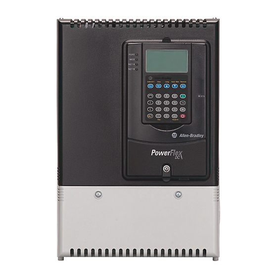
Rockwell Automation Allen-Bradley PowerFlex 20P Manual (142 pages)
PowerFlex Digital DC Drive - Frame D
Brand:
Rockwell Automation
| Category:
Industrial Equipment
| Size: 11.32 MB
Table of Contents
Table of Contents
3
Summary of Changes
7
Introduction
9
Chapter 1
10
General Safety Precautions
10
Hardware Description
11
Commonly Used Tools
12
Service Tools
12
Software Tools
12
Chapter 2 Introduction
13
Save the Parameter Configuration
14
Save to a HIM Set
14
Save Parameters to a Project File Using Connected Components Workbench Software
15
Save Parameters to an Offline Node File Using Driveexecutive
16
Software
16
Visual Component Inspection
16
Troubleshoot a Control Power Supply Failure
17
Testing the Switching Power Supply and Pulse Transformer
18
Boards
18
Testing the Control and Field Board Connections
19
Troubleshoot an AC Undervoltage Fault
22
Troubleshoot an Armature Bridge Failure
23
Troubleshoot a Field Current Loss Fault
25
Low or Incorrect Field Current
25
No Field Current
27
Power Component Test Procedures
29
Check the Armature SCR Modules
29
Check the Pulse Transformer Board
33
Check the Field Scr/Dual Diode Module
34
Speed Feedback Device Tests
37
Check the Encoder
37
Check the DC Tachometer
37
Check the Resolver Interface Board
38
Thermistors and Thermal Switches
40
Relay Outputs
40
Create a Fault Report
41
What You Need When You Call Tech Support
41
Component Test Procedures
13
Chapter 3 Introduction
43
Remove Power from the Drive
44
Access Procedures
43
Topic Page
44
Field Circuit Fuse Removal and Installation
45
Remove the Field Circuit Fuses
45
Install the Field Circuit Fuses
45
DPI / HIM Assembly Removal and Installation
46
Remove the DPI / HIM Assembly from the Protective Cover
46
Install the DPI / HIM Assembly on the Protective Cover
46
Protective Cover Removal and Installation
47
Remove the Protective Covers
47
Install the Protective Covers
48
Open and Close the Control Panel
49
Open the Control Panel
49
Close the Control Panel
49
Communication Adapter and EMI Shield Removal and Installation
50
Remove the Communication Adapter and EMI Shield
50
Install the Communication Adapter and EMI Shield
51
Switching Power Supply Fuse Removal and Installation
52
Board
52
Remove the Resolver Feedback and Interface Circuit Boards
54
Resolver Feedback and Interface Circuit Board Removal and Installation
54
Install the Resolver Feedback and Interface Circuit Boards
57
Board
58
I/O Expansion Circuit Board Removal and Installation
58
Remove the I/O Expansion Circuit Board
58
Install the I/O Expansion Circuit Board
59
AC to 24V DC I/O Converter Circuit Board Removal and Installation
60
Resolver Feedback and Interface Circuit Board Removal and Installation
58
Control Circuit Board Removal and Installation
61
Remove the Control Circuit Board
61
Install the Control Circuit Board
64
Installation
61
Board
61
Install the 115V AC to 24V DC I/O Converter Circuit
61
Switching Power Supply Circuit Board Removal and Installation
65
Remove the Switching Power Supply Circuit Board
65
Install the Switching Power Supply Circuit Board
66
Pulse Transformer Circuit Board Removal and Installation
66
Remove the Pulse Transformer Circuit Board
66
Install the Pulse Transformer Board
69
Field Circuit Board Removal and Installation
70
Remove the Field Circuit Board
70
Install the Field Circuit Board
71
Field SCR and Dual Diode Module Removal and Installation
72
Remove the Field SCR and Dual Diode Modules
72
Install the Field SCR and Dual Diode Modules
73
Field Fuse Holder Removal and Installation
74
Remove the Field Fuse Holder
74
Install the Field Fuse Holder
76
Fan Starting Capacitor Removal and Installation
76
Remove the Fan Starting Capacitor
76
Install the Fan Starting Capacitor
77
Series a Fan Circuit Board Removal and Installation
78
Remove the Series a Fan Circuit Board
78
Install the Series a Fan Circuit Board
78
Series B Fan Circuit Board Removal and Installation
79
Remove the Series B Fan Circuit Board
79
Install the Series B Fan Circuit Board
79
Series a Fan Assembly Removal and Installation
80
Remove the Series a Fan Assembly
80
Install the Series a Fan Assembly
81
Series B Fan Assembly Removal and Installation
82
Remove the Series B Fan Assembly
82
Install the Series B Fan Assembly
83
Series C Fan Assembly Removal and Installation
84
Remove the Series C Fan Assembly
84
Install the Series C Fan Assembly
85
AC Current Transducers Removal and Installation
86
Remove the AC Current Transducers
86
Install the AC Current Transducers
89
Overvoltage Clipping Circuit Board Fuse Removal and Installation
90
Remove the Overvoltage Clipping Circuit Board Fuses
90
Install the Overvoltage Clipping Circuit Board Fuses
90
Overvoltage Clipping Circuit Board Removal and Installation
91
Remove the Overvoltage Clipping Circuit Board
91
Install the Overvoltage Clipping Circuit Board
92
Armature Leg Fuse Removal and Installation
92
Remove the Armature Leg Fuse
92
Install the Armature Leg Fuse
93
SCR Module Leg Assembly Removal and Installation
94
Remove the SCR Module Leg Assembly
94
Install the SCR Module Leg Assembly
99
Bimetal Thermostat Removal and Installation
100
Remove the Bimetal Thermostat
100
Install the Bimetal Thermostat
100
Discharge Resistors Removal and Installation
100
Remove the Discharge Resistors
100
Install the Discharge Resistors
102
Inrush Limiting Resistor Removal and Installation
102
Remove the Inrush Limiting Resistor
102
Install the Inrush Limiting Resistor
104
Snubber Capacitors Removal and Installation
104
Remove the Snubber Capacitors
104
Install the Snubber Capacitors
105
Snubber Resistors Removal and Installation
106
Remove the Snubber Resistors
106
Install the Snubber Resistors
107
Chapter 4 Test with the Motor, Without a Mechanical Load
109
Appendix A List of Schematic Diagrams
111
List of Circuit Board Layouts
123
Appendix B
124
Pulse Transformer Board
124
Pulse Transformer Board Layout
124
Pulse Transformer Board to Field Board Connections
125
Pulse Transformer Board to Switching Power Supply Connections
125
Pulse Transformer Board to Bimetal Thermostat Connections
125
Pulse Transformer Board to Field Scr/Dual Diode Module Connections
125
Pulse Transformer Board to Control Board Connections
126
Switching Power Supply Board
127
Pulse Transformer Board to Current Transducer Connections
127
Switching Power Supply Board Layout
127
Switching Power Supply Board to Control Board Connections
127
Control Board
128
Control Board Layout
128
Control Board to Field Board Connections
128
Field Board
129
Field Board Layout
129
Overvoltage Clipping Board
130
Overvoltage Clipping Board to Pulse Transformer Board Connections
130
Appendix C List of Flow Charts
131
Control Power Supply Failure
132
Field Current Loss Failure
133
No Field Current
133
Low or Incorrect Field Current
134
Appendix D TG004C-EN-P, September 2021
135
TG004B-EN-P, October 2013
135
Index
137
Advertisement
Rockwell Automation Allen-Bradley PowerFlex 20P Hardware Service Manual (130 pages)
Digital DC Drive Frame B
Brand:
Rockwell Automation
| Category:
DC Drives
| Size: 7.26 MB
Table of Contents
Table of Contents
3
Additional Resources
7
Preface
7
Summary of Changes
7
General Safety Precautions
10
Chapter 1
11
Hardware Description
11
Commonly Used Tools
12
Service Tools
12
Software Tools
12
Component Test Procedures
13
Chapter 2 Component Test Procedures Save the Parameter Configuration
14
Visual Component Inspection
15
Troubleshoot a Control Power Supply Failure
15
Testing the Switching Power Supply and Pulse Transformer
16
Boards
16
Testing the Control and Field Board Connections
16
Troubleshoot an AC Undervoltage Fault
19
Troubleshoot an Armature Bridge Failure
20
Troubleshoot a Field Current Loss Fault
22
Low or Incorrect Field Current
22
No Field Current
24
Power Component Test Procedures
26
Check the Armature SCR Modules
26
Check the Pulse Transformer Board
30
Check the Field Scr/Dual Diode Module
32
Speed Feedback Device Tests
34
Check the Encoder
34
Check the DC Tachometer
35
Check the Resolver Interface Board
35
Thermistors and Thermal Switches
37
Relay Outputs
37
Create a Fault Report
38
What You Need When You Call Tech Support
38
Save the Parameter Configuration
14
Save to a HIM Set
14
Replacement Parts Kits
40
Part Replacement Procedures Replacement Parts Kits
40
Chapter 3
42
Remove Power from the Drive
42
DPI / HIM Assembly Replacement
42
Remove the DPI / HIM Assembly
42
Install the DPI / HIM Assembly
43
Protective Cover Replacement
43
Remove the Protective Covers
43
Install the Protective Covers
45
Communication Adapter and Electromagnetic Interference Shield Replacement
46
Shield Replacement
46
Remove the Communication Adapter and Electromagnetic
46
Interference Shield
46
Install the Communication Adapter and EMI Shield
47
Resolver Feedback and Interface Circuit Board Replacement
48
Remove the Resolver Feedback and Interface Circuit Boards
48
Install the Resolver Feedback and Interface Circuit Boards
51
I/O Expansion Circuit Board Replacement
52
Remove the I/O Expansion Circuit Board
52
Install the I/O Expansion Circuit Board
53
Replacement
54
Remove the 115V AC to 24V DC I/O Converter Circuit
54
Board
54
AC to 24V DC I/O Converter Circuit Board Replacement
54
Install the 115V AC to 24V DC I/O Converter Circuit
55
Board
55
Control Circuit Board Replacement
55
Remove the Control Circuit Board
55
Install the Control Circuit Board
58
Control Electromagnetic Interference Shield Removal and Closure
58
Move the Control Electromagnetic Interference Shield
58
Close the Control EMI Shield in the Service Position
59
Switching Power Supply Board Fuse Replacement
60
Remove the Fuses on the Switching Power Supply Circuit
60
Board
60
Board
62
Pulse Transformer Circuit Board Fuse Replacement
62
Remove the Fuses on the Pulse Transformer Circuit Board
62
Install the Fuses on the Pulse Transformer Circuit Board
62
Pulse Transformer and Switching Power Supply Circuit Boards Replacement
62
Replacement
62
Remove the Pulse Transformer and Switching Power Supply
62
Circuit Boards
62
Rockwell Automation Publication 20P-TG002B-EN-P - February
63
Configure the Pulse Transformer Circuit Board
69
Install the Pulse Transformer and Switching Power Supply
72
Boards
74
Field Circuit Fuses Replacement
74
Remove the Field Circuit Fuses
74
Install the Field Circuit Fuses
75
Field Circuit Board Replacement
75
Remove the Field Circuit Board
75
Install the Field Circuit Board
76
Field SCR and Dual Diode Modules Replacement
77
Remove the Field SCR and Dual Diode Modules
77
Install the Field SCR and Dual Diode Modules
77
AC Line Snubber Circuit Board and Resistors Replacement
78
Remove the AC Line Snubber Circuit Board and Resistors
78
Install the AC Line Snubber Circuit Board and Resistors
80
SCR Modules Replacement
80
Remove the SCR Modules
80
Install the SCR Modules
88
AC Current Transducers Replacement
90
Remove the AC Current Transducers
90
Install the AC Current Transducers
93
Bimetal Thermostats Replacement
94
Remove the Bimetal Thermostats
94
Install the Bimetal Thermostats
99
Cooling Fan Replacement
99
Remove the Cooling Fans
99
Install the Cooling Fans
101
Chapter 4 Test with the Motor, Without a Mechanical Load
103
Start-Up after Repair
103
Appendix A List of Schematic Diagrams
105
Appendix B
113
List of Circuit Board Layouts
113
Pulse Transformer Board
114
Switching Power Supply Board
118
Control Board
119
Field Board
120
Circuit Board Layouts and Connections
113
Appendix C List of Flow Charts
121
Control Power Supply Failure
122
Field Current Loss Failure
123
No Field Current
123
Low or Incorrect Field Current
124
Index
125
Rockwell Automation Allen-Bradley PowerFlex 20P Instructions Manual (78 pages)
DC Drive and Field Controller
Brand:
Rockwell Automation
| Category:
DC Drives
| Size: 6.11 MB
Table of Contents
Table of Contents
1
Summary of Changes
2
The Powerflex DC Drive
3
The Powerflex DC Field Controller
4
The Powerflex DC Standalone Regulator
5
Unsurpassed Capability in Network Communication
5
Powerflex DC Drive Catalog Number Explanation
6
Powerflex DC Field Controller Catalog Number Explanation
9
Powerflex DC Field Controller Product Selection
9
Factory-Installed Options
10
User-Installed Options
10
Isolation Transformers
12
Installation Considerations
21
Typical Power Wiring Diagrams
24
Powerflex DC Drives Terminal Block Locations
30
Powerflex DC Drives and Field Controller Circuit Protection
48
Mounting
61
Approximate Dimensions - Powerflex DC Drives
62
Approximate Dimensions and Weights - Powerflex DC Field Controllers
68
Powerflex DC Drive Specifications
70
Powerflex DC Field Controller Specifications
73
IP20 NEMA/UL Type Open Watts Loss
74
Additional Resources
77
Advertisement
Advertisement
Related Products
Rockwell Automation 20P41AB7P0RA0NNN
Rockwell Automation 20P41AB9P0RA0NNN
Rockwell Automation 20P41AB012RA0NNN
Rockwell Automation 20P41AB020RA0NNN
Rockwell Automation 20P41AB029RA0NNN
Rockwell Automation 20P41AB038RA0NNN
Rockwell Automation 20P41AB055RA0NNN
Rockwell Automation 20P41AB073RA0NNN
Rockwell Automation 20P41AB093RA0NNN
Rockwell Automation 20P41AB110RA0NNN
Rockwell Automation Categories
Controller
Control Unit
Power Supply
DC Drives
Industrial Equipment
More Rockwell Automation Manuals
Login
Sign In
OR
Sign in with Facebook
Sign in with Google
Upload manual
Upload from disk
Upload from URL