Sign In
Upload
Manuals
Brands
Rockwell Automation Manuals
Industrial Equipment
Allen-Bradley iTRAK 5750 System
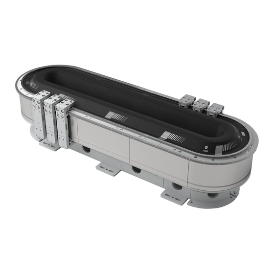
Rockwell Automation Allen-Bradley iTRAK 5750 System Manuals
Manuals and User Guides for Rockwell Automation Allen-Bradley iTRAK 5750 System. We have
1
Rockwell Automation Allen-Bradley iTRAK 5750 System manual available for free PDF download: Manual
Rockwell Automation Allen-Bradley iTRAK 5750 System Manual (250 pages)
Brand:
Rockwell Automation
| Category:
Industrial Equipment
| Size: 59 MB
Table of Contents
Table of Contents
3
Preface
9
Conventions
9
Appropriate Use
9
Additional Resources
9
Itrak 5750 and Kinetix System Resources
9
Programmable Controllers Resources
10
Ethernet/Ip Resources
10
CIP Security Resources
10
Functional Safety Resources
10
Product Overview
11
About the Itrak 5750 System
11
Catalog Number Explanations
17
Assembled Itrak 5750 System
17
Modular Itrak 5750 System Components
18
Motor Modules
22
Motor Module Status Indicators
27
Connector Modules
27
Connector Module Status Indicators
30
Integrated Support Frame
31
Rail System
33
Straight Rail Segments
33
Curve Rail Segments
34
Infield Cover
35
Mover
36
Power Supplies
37
Programmable Controllers
37
Typical Communication Configurations
38
Linear Topology
38
Device Level Ring Topology
39
Star Topology
40
Safety Information
41
Risk Assessment
41
General Assembly Instructions
41
Machine Guarding
42
Avoid Accidents, Injury, and Property Damage
43
Remove Power from the Itrak 5750 System
43
Avoid Electrical Shock
44
Protection against Contact with Hot Parts
44
Protection against Magnetic and Electromagnetic Fields
44
Safe Magnet Handling
47
Mover Motor Magnet Plate Keeper
47
CIP Security
48
Storage
48
Mechanical Installation
49
Installation Safety
50
General Handling Instructions
50
Installation Tools
51
Hardware Specifications
51
Unpack and Find the Weight of the Track
52
Prepare the Mounting Site or Structure
53
Applications that Require Subframe Mounting
53
Mounting Surface Requirements
53
Mounting Plate Dimensions
53
Plan Lubrication Segment Locations
54
Move a Track Section
55
Install an Oval Track
56
Install a Rectangle Track
61
Electrically Ground the Track
70
Install the Lubrication System
71
What You Need
71
Mount the Lubricator Pumps
72
Lubrication Pump Wiring
74
Lubrication Pump Configuration
74
Power and Communication Connections
75
Typical Itrak 5750 System
76
Provide Power to the Itrak System
77
Connect Power to the Itrak 5750 System
78
One Itrak Power Supply
78
Multiple Itrak Power Supplies
79
Connect the Power Cable
80
Connect an Ethernet/Ip Network to the Itrak 5750 System
80
Ethernet/Ip Address Rotary Switches
80
Communication Control DIP Switch
83
Connect the Ethernet Cable
84
Cybersecurity Considerations
85
Configuration and Startup
87
Studio 5000 Logix Designer
87
Configure the Itrak 5750 System
88
Set the IP Address
88
Protected Mode
88
Configure and Customize the Project File
90
Configure the Controller
90
Configure the Kinetix 5700 Power Supply
92
Configure the Kinetix 5700 Itrak Power Supply
96
Configure the Itrak 5750 Motor Modules
99
Continue Itrak 5750 Motor Module Configuration
104
Configure the Motion Group
110
Configure the Section Axis Properties
112
Configure the Mover Axis Properties
113
Download the Program
116
Apply Power to the Itrak 5750 System
117
Bus-Sharing Group Configuration
118
Bus-Sharing Groups Example
118
Configure Bus-Sharing Groups
120
Commission the Itrak 5750 System
122
Motor Module Section Gap Position Compensation
122
Calculate and Store Position Gap Compensation Values
123
Tune the Axes
123
Tune the Axes with Load Observer
123
Troubleshooting
127
Safety Precautions
127
Interpret Fault Codes
127
Fault Code Overview
128
Mover Numbers in Fault Codes
129
Motor Module Numbers in Fault Codes
129
Interpret Status Indicators
129
Motor Module Status Indicators
129
Connector Module Status Indicators
131
Axis Troubleshooting
132
Logix 5000 Controller and Itrak System Behavior
134
Kinetix 5700 Itrak Power Supply Behavior
135
Itrak 5750 Motor Module and Mover Behavior
135
Maintenance
139
Before You Begin Maintenance
139
Preventive Maintenance
139
Install or Replace Components
140
Replacement Hardware
140
Installation and Replacement Procedure List
140
Replace a Mover Position Magnet Assembly
141
Replace a Mover Motor Magnet
143
Replace a Mover
144
Replace a Straight Motor Module
147
Replace a Curve Motor Module
150
Replace Mover Cam-Follower Wheels or Flexures
153
Replace a Lubrication Segment of a Top or Bottom Rail
162
Replace a Straight Segment of the Top or Bottom Rail
164
Replace a Curve Segment of the Top or Bottom Rail
168
Replace a Lubrication Segment of a Middle Rail
173
Replace a Straight Segment of the Middle Rail
174
Replace a Curve Segment of the Middle Rail
177
Replace a Connector Module
180
Replace an Infield Cover
181
Replace a Lubricant Cartridge
182
Lubrication
182
Lubrication Using an Itrak Lubrication System
182
Lubrication Using a Customer Provided Oil Bleed System
187
Certification
189
Important Safety Considerations
189
Safety Application Requirements
190
Category 3 Requirements According to en ISO 13849-1
190
Stop Category Definition
190
Performance Level (PL) and Safety Integrity Level (SIL)
190
Probability of Dangerous Failure Per Hour
191
Out-Of-Box State
191
Out-Of-Box State Support
191
Safe Torque off Function
194
Safe Torque off (STO) Function Operation
194
Safe Torque off (STO) State Reset
196
Safe Torque off (STO) Specifications
196
Safe Torque off (STO) Assembly Tags
197
Safe Torque off (STO) Mode
198
Safe Torque off (STO) Behavior in an Itrak 5750 System
198
Itrak 5750 System Safety Considerations
198
Functional Safety Considerations
199
Timed SS1 Stopping Function
199
Safety Function Operation
199
Timed SS1 Request Removed
202
Motion Direct Commands in Motion Control Systems
203
Safe Torque off Bypass When Using Motion Direct Commands
203
Studio 5000 Application Warning Messages
204
Torque Permitted in a Multi-Workstation Environment
206
Warning Icon and Text in Axis Properties
206
Explicit Messages
208
Safe Monitor Network Communication
209
Troubleshoot the Safe Stop Function
214
Integrated Safety Motor Module Replacement
214
Replace an Integrated Safety Motor Module in a Guardlogix System
215
Configure Only When no Safety Signature Exists
215
Configure Always
216
Update the System Firmware
217
Before You Begin
217
Inhibit the Module
218
Update Your Firmware
219
Use Controlflash Plus to Update Your Itrak 5750 System Firmware
219
Use Controlflash to Update Your Itrak 5750 System Firmware
223
Configure Your Communication Path with Rslinx
223
Start the Controlflash Software
225
Verify the Firmware Update
229
High-Speed Data Logging Service
231
Configure and Use the Message Instruction
231
Itrak System Data Logging Parameters
239
Advertisement
Advertisement
Related Products
Rockwell Automation iTRAK
Rockwell Automation POINT I/O
Rockwell Automation ics triplex AADvance
Rockwell Automation Allen-Bradley IF2
Rockwell Automation ICSTT-RM280N-EN-P
Rockwell Automation 1771-IFMS
Rockwell Automation 1794-TB3GT
Rockwell Automation 2198T
Rockwell Automation 25A
Rockwell Automation 25A-A2P5N114
Rockwell Automation Categories
Controller
Control Unit
Power Supply
DC Drives
Industrial Equipment
More Rockwell Automation Manuals
Login
Sign In
OR
Sign in with Facebook
Sign in with Google
Upload manual
Upload from disk
Upload from URL