Sign In
Upload
Manuals
Brands
Rockwell Automation Manuals
Relays
Allen-Bradley Guardmaster 440R-GL2S2P
Rockwell Automation Allen-Bradley Guardmaster 440R-GL2S2P Manuals
Manuals and User Guides for Rockwell Automation Allen-Bradley Guardmaster 440R-GL2S2P. We have
1
Rockwell Automation Allen-Bradley Guardmaster 440R-GL2S2P manual available for free PDF download: User Manual
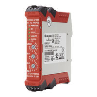
Rockwell Automation Allen-Bradley Guardmaster 440R-GL2S2P User Manual (68 pages)
Guard Locking Proximity Inputs Safety Relay
Brand:
Rockwell Automation
| Category:
Relays
| Size: 8 MB
Table of Contents
Table of Contents
3
About this Publication
7
Who Should Use this Manual
7
Firmware Revision History
7
Definitions
7
Summary of Changes
8
Additional Resources
8
Overview
9
Hardware Features
9
Logic Functions
10
Logic Setting 1 - Cat 1 Stop, Logic in off
10
Logic Setting 2 - Cat 1 Stop with Logic in
10
Logic Setting 3 - Safe Limited Slow Speed, Logic in off
11
Logic Setting 4 - Safe Limited Slow Speed with Logic in
11
Logic Setting 5
11
Automatic Reset
11
Logic Setting 8 - Speed Status Only
12
Installation
13
Mounting Dimensions
13
DIN Rail Mounting and Removal
13
Removal
14
Spacing
14
Removable Terminals
14
Enclosure Considerations
14
Help Prevent Excessive Heat
15
Power, Ground, and Wire
17
Wiring Requirements and Recommendation
17
Wire Size
17
Terminal Torque
17
Terminal Assignments
17
Ground the Controller
18
Connect a Power Supply
18
Proximity Sensor Connections
19
Guard Locking Connections
20
Devices with Mechanical Contacts
20
Safety Devices with OSSD Outputs
20
Unlock Request Input
21
Lock and Reset Request Input
21
Lock and Unlock Signals
21
Lock Outputs
22
TLS3-GD2 Guard Locking Switch Connections
22
TLS-Z Guard Locking Switch, 440G-LZ Guard Locking Switch, and MAB Connections
22
Single Wire Safety (SWS) Connections
23
Multiple Guard Locking Devices and Power to Lock
23
No Guard Locking
24
Safety Outputs
24
Single Wire Safety (SWS)
25
Logic Switch Settings
27
SLS1 Switch Setting
27
Case 1
27
Case 2
28
Sls2/Time Switch Setting
28
Configuration Process
29
Status Indicators During Power-Up
31
Status Indicators During Normal Operation
31
Status Indicators During Diagnostics
32
Introduction to Pulse Testing
33
Pulse Testing for Inputs
33
Test of OSSD Outputs
34
Webpage
35
Logix AOP
36
Proximity Sensor Selection
39
Proximity Sensor Targets
39
Stop Cat 1 Example
43
Example Schematic
43
Sequence Diagram
44
Sequence Steps
44
Example with EMSS Contacts
45
Example Schematic with Mechanical Guard Locking Outputs
45
SLS Example
47
Example Schematic
47
Sequence Diagram
48
Sequence Steps
49
Delayed Unlock with Auto Reset Example
50
Example Schematic
50
Sequence Diagram
51
Sequence Steps
51
Status Only Example
52
Example Schematic
52
Sequence Diagram
53
Sequence Steps
53
Specifications
55
General Specifications
55
Environmental Specifications
55
Input IN1
56
Proximity Sensor Signals
56
Lock Unlock Request
56
Lock Unlock Signals
57
Auxiliary Signal
57
Single Wire Safety Input Signal
57
Single Wire Safety Output Signal
58
Safety/Pulse Test Outputs
58
Response Times
58
Regulatory Approvals
59
Agency Certifications
59
Declaration of Conformity
59
CE Conformity
59
UKCA Conformity
60
SIL Rating
60
Performance Level/Category
60
Index
63
Advertisement
Advertisement
Related Products
Rockwell Automation Allen-Bradley 440R-GL2S2T
Rockwell Automation Allen-Bradley Guardmaster 440R-S35013
Rockwell Automation Allen-Bradley Guardmaster 440R-S35011
Rockwell Automation Allen-Bradley Guardmaster 440R-S35014
Rockwell Automation Allen-Bradley Guardmaster 440R-S35016
Rockwell Automation 440R-D22S2
Rockwell Automation 440R-EM4R2
Rockwell Automation 440R-EM4R2D
Rockwell Automation Guardmaster Allen-Bradley 440R-S35002
Rockwell Automation Guardmaster Allen-Bradley 440R-W23219
Rockwell Automation Categories
Controller
Control Unit
Power Supply
DC Drives
Industrial Equipment
More Rockwell Automation Manuals
Login
Sign In
OR
Sign in with Facebook
Sign in with Google
Upload manual
Upload from disk
Upload from URL