Sign In
Upload
Manuals
Brands
Rockwell Automation Manuals
Controller
Allen-Bradley 856T-B24LC
Rockwell Automation Allen-Bradley 856T-B24LC Manuals
Manuals and User Guides for Rockwell Automation Allen-Bradley 856T-B24LC. We have
1
Rockwell Automation Allen-Bradley 856T-B24LC manual available for free PDF download: User Manual
Rockwell Automation Allen-Bradley 856T-B24LC User Manual (82 pages)
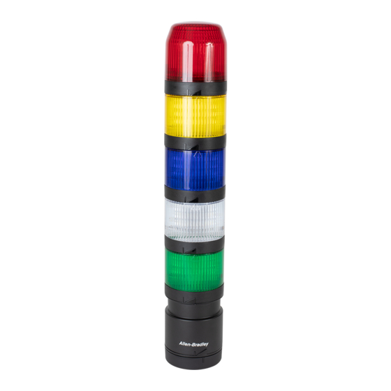
Control Tower IO-Link Class B Light and Sound Module Controller
Brand:
Rockwell Automation
| Category:
Controller
| Size: 4 MB
Table of Contents
Table of Contents
3
Abbreviations
7
Download Firmware, AOP, EDS, and Other Files
7
Preface
7
Who Should Use this Manual
7
Additional Resources
8
Chapter 1 Operation Modes
9
IO-Link Features
9
Product Features
9
Product Overview
9
Installation
10
Wiring
12
Chapter 2 What Is IO-Link
13
IO-Link Overview
13
Why IO-Link
13
Seamless Integration
13
Real-Time Diagnostics and Trending
14
IO-Link Device Status
14
Device Profiles and Automatic Device Configuration
14
Descriptive Tags
14
How IO-Link Works
14
Transmission Rates
15
Transmission Quality
15
Response Time of the IO-Link System
15
IO-Link Data Types
15
Process Data
15
Value Status
16
Device Data
16
Events
16
Access IO-Link Data
16
Cyclic Data
16
Acyclic Data
16
I/O System Startup
16
Assign Device Parameters
17
Chapter 3
19
Hardware
19
Software
19
Products Required
19
AOP Installation
20
Create Project
20
Add Controller
21
Add POINT I/O Ethernet Adapter
22
Add IO-Link Master
23
Register the 856T-B24LC Module IODD File
24
Embedded IODD File
25
Download IODD File
27
Connect the 856T-B24LC Module to the IO-Link Master
29
Download the Project to the PLC
30
Chapter 4 Display Parameters
33
IO-Link Tabs
34
Common Tab
35
Identification Tab
36
Observation Tab
37
Parameter Tab
39
Diagnosis Tab
41
Chapter 5
43
Non-Recoverable
43
Critical
44
Severe
44
Hardware Fault Conditions
43
Device Status Indicator -Error Codes
44
IO-Link Status Indicator Timing
44
Chapter 6
45
Maximum Number of Light/Sound Modules in the Stack Light
45
Patchcord
45
Inrush Current Calculation
46
Overcurrent Protection
46
Chapter 7
47
Configure a Message Instruction
47
Example Format of a Read Message
47
Example Format of a Write Message
49
Read Data from the IO-Link Module
49
Service Code
51
Source Length: from Data Structure Tables
52
Appendix A IO-Link Module Specifications
53
Validation of Write
51
Approximate Dimensions
54
Light and Sound Module Operation Mode
55
Appendix B Identification Tab
57
Observation Tab
57
Parameter Tab
61
Diagnostics Tab
64
IO- Link System Commands
65
Process Data Input
66
Process Data Output
67
Configuration Tables
67
Appendix D Operational State
69
Short Circuit
70
Events
71
Appendix E Reset to Factory Settings - Variables
73
Reset All Statistics -Variables
74
Appendix F Error Resolution
75
Index
77
Advertisement
Advertisement
Related Products
Rockwell Automation Allen-Bradley 1769 Compact GuardLogix
Rockwell Automation Allen-Bradley 5069 Compact GuardLogix
Rockwell Automation Allen-Bradley 1756 GuardLogix
Rockwell Automation Allen-Bradley MicroLogix
Rockwell Automation Allen-Bradley GuardLogix
Rockwell Automation Allen-Bradley MicroLogix 1400 Series
Rockwell Automation Allen-Bradley PowerFlex 70
Rockwell Automation Allen-Bradley PowerFlex Series
Rockwell Automation Allen-Bradley PowerFlex 525
Rockwell Automation Allen-Bradley PowerFlex 4M
Rockwell Automation Categories
Controller
Control Unit
Power Supply
DC Drives
Industrial Equipment
More Rockwell Automation Manuals
Login
Sign In
OR
Sign in with Facebook
Sign in with Google
Upload manual
Upload from disk
Upload from URL