Sign In
Upload
Manuals
Brands
Rockwell Automation Manuals
I/O Systems
Allen-Bradley 5069-OW4I
Rockwell Automation Allen-Bradley 5069-OW4I Manuals
Manuals and User Guides for Rockwell Automation Allen-Bradley 5069-OW4I. We have
1
Rockwell Automation Allen-Bradley 5069-OW4I manual available for free PDF download: User Manual
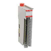
Rockwell Automation Allen-Bradley 5069-OW4I User Manual (156 pages)
Digital I/O Modules
Brand:
Rockwell Automation
| Category:
I/O Systems
| Size: 15 MB
Table of Contents
Table of Contents
3
Preface
7
About this Publication
7
Download Firmware, AOP, EDS, and Other Files
7
Summary of Changes
7
Topic Page
7
Terminology
8
Additional Resources
9
Digital I/O Module Operation in a Control System
11
Controller and Software Compatibility
12
Types of Modules
13
Module Overview
14
Local I/O Modules or Remote I/O Modules
15
Local I/O Modules
15
Remote I/O Modules
16
Limit Access to the System
18
Ownership
18
Multiple Owners of Compact 5000 Standard Input Modules
19
Configuration Changes in a Standard Input Module with Multiple Owners
19
Construct a System
20
Local I/O Modules
20
Remote I/O Modules
20
Use a 5069-ARM Address Reserve Module
21
Power the Modules
22
Establish a New or Isolated SA Power Bus
23
Power Requirements for Compact 5000 I/O Safety Modules
24
Configure the Modules
26
Connections with Standard I/O Modules
26
Connections with the Safety I/O Modules
28
Connection over an Ethernet/Ip Network
30
Input Module Data
31
Trigger Events
31
Output Module Data
32
Listen Only Connections
33
Connection over Ethernet/Ip
33
Additional Considerations with Listen-Only Connections
34
External Means
34
Protected Operations
35
Considerations Specific to Safety I/O Modules
35
Overall System Safety Function
36
Single-Channel or Dual-Channel Mode
36
Determine Conformity
36
Safety Precautions
37
Safety Application Requirements
38
Safe State
38
Configuration Signature and Ownership
39
Reset Safety I/O Modules to Out-Of-Box State
40
Input Module Compatibility
41
Output Module Compatibility
42
Software Configurable
42
Module Data Quality Reporting
42
Fault and Status Reporting
43
Inhibit a Module
43
Electronic Keying
44
Module Firmware
44
Producer/Consumer Communication
45
Use CIP Sync Time with Fast I/O Modules
45
CIP Sync Time Stamps
46
Input Module Features
47
Input Module Types
47
Data Transfer at RPI or Change of State
48
Software Configurable Input Filters and Delays
48
Standard Input Modules
48
Compact 5000 I/O Safety Input Modules
49
Input Filter with Compact 5000 I/O Fast Input Modules
49
Simple Count Mode
50
Sequence of Events Per Point Time Stamps
50
Chatter Detection
51
Events
51
Event Definition
52
Independent Point Trigger
52
Pattern Match Trigger
53
Additional Event Considerations
53
Pulse Latching
54
Field Power Loss Detection
55
Short Circuit Protection
56
Muting Lamp Fault and Short Circuit Diagnostics Triggered
56
Test Output Recovery after Overload or Short Circuit to Ground Condition
57
Thermal Shutoff
57
Fault and Status Reporting
58
Output Module Features
59
Output Module Types
59
Data Echo
60
Field Power Loss Detection
60
No Load Detection
61
No Load Detection in Standard Output Modules
61
No Load Detection in Safety Output Modules
62
Short Circuit Protection
62
Short Circuit Protection in Standard Output Modules
62
Short Circuit Protection in Safety Output Modules
63
Thermal Shutoff
65
Thermal Shutoff with Standard Output Modules
65
Thermal Shutoff with a Safety Output Module
65
Output State Change Time
66
Configurable Channel-Level Output State in Program Mode or Fault Mode
66
Connection Fault Handling
66
Forces
67
Enable or Disable Forces
67
Force Status
67
Time-Scheduled Output Control
68
Use an MAOC Instruction with a 5069-OB16F Module
69
Isolated and Non-Isolated Output Modules
70
Fault and Status Reporting
70
Safety I/O Module Features
71
Safety Input Module Features
72
Safety Application Suitability Levels
72
Use Test Output with a Safety Input
73
Single-Channel Mode
74
Safety Input Fault Recovery
74
Safety Input Delay Time
75
Muting Lamp Operation
76
Discrepancy
77
Safety Output Module Features
79
Safety Application Suitability Levels
79
Safety Output with Test Pulse
80
Single-Channel Mode
81
Dual-Channel Mode
82
Safety Output Fault Recovery
83
Fault and Status Reporting
83
Configure a Standard I/O Module
85
Before You Begin
85
Create a New Module
86
Go Online and Discover Local I/O Modules
86
Remain Offline and Add New Local I/O Modules
87
Go Online and Discover Remote I/O Modules
89
Remain Offline and Add New Remote I/O Modules
90
Reserve an I/O Module Slot
92
Add the 5069-ARM Module to the Project
92
Delete the 5069-ARM Module from the Project
92
Configure the Module Parameters
93
Common Module Parameters
93
Module-Specific Parameters
95
Configure and Replace Safety I/O Modules
99
Before You Begin
99
Create a New Module
100
Remain Offline and Add New Local Safety I/O Modules
100
Remain Offline and Add New Remote Safety I/O Modules
101
Configure the Module Parameters
103
Module-Specific Parameters
106
View the Module Tags
107
Replace a Safety I/O Module
107
Set the SNN Manually
108
Reset to Out-Of-Box Configuration
109
Replace a Module in a Logix 5000 System
110
Troubleshoot the Module
111
Troubleshoot with the Status Indicators
111
Module Status Indicator
114
SA Status Indicator - Safety I/O Modules
114
I/O Status Indicators
115
Troubleshoot with the Studio 5000 Logix Designer Application
116
Alert in the I/O Configuration Tree
116
Status and Fault Information on the Parameter Pages
116
Module and Point Diagnostics
118
Studio 5000 Logix Designer Application Tag Editor
120
Internal Faults on a Safety Output Module
120
Module Tags
121
View the Tags
122
Standard Input Module Tags
123
Standard Output Module Tags
128
Safety I/O Module Tags
130
Application and Wiring Examples for Safety I/O Modules
134
Input Device Connection Details
134
Wiring Diagrams - 5069-IB8S, 5069-IB8SK
136
Wiring Diagrams - 5069-OBV8S, 5069-OBV8SK
138
Bipolar Mode
138
Sourcing Mode
140
Wiring Faults on Safety Modules
142
Safety Data for Safety I/O Modules
143
Compact 5000 Safety I/O Modules Safety Data
144
Safety Reaction Time
144
Safety I/O Module Diagnostic Assembly
145
Create User-Defined Diagnostic Assembly Types
145
Safety Input Module Diagnostics
146
Safety Output Module Diagnostics
149
Configure the Message Type User Tags
151
Index
153
Advertisement
Advertisement
Related Products
Rockwell Automation Allen-Bradley 5069-OA16
Rockwell Automation Allen-Bradley 5069-OB8
Rockwell Automation Allen-Bradley 5069-OBV8S
Rockwell Automation Allen-Bradley 5069-OBV8SK
Rockwell Automation Allen-Bradley 5069-OB16
Rockwell Automation Allen-Bradley 5069-OB16F
Rockwell Automation Allen-Bradley 5069-OB16K
Rockwell Automation Allen-Bradley 5069-OW16
Rockwell Automation Allen-Bradley 5069-OX4I
Rockwell Automation Allen-Bradley 5069-L310ER
Rockwell Automation Categories
Controller
Control Unit
Power Supply
DC Drives
Industrial Equipment
More Rockwell Automation Manuals
Login
Sign In
OR
Sign in with Facebook
Sign in with Google
Upload manual
Upload from disk
Upload from URL