Sign In
Upload
Manuals
Brands
Rockwell Automation Manuals
Control Unit
Allen-Bradley 1746-HSCE
Rockwell Automation Allen-Bradley 1746-HSCE Manuals
Manuals and User Guides for Rockwell Automation Allen-Bradley 1746-HSCE. We have
1
Rockwell Automation Allen-Bradley 1746-HSCE manual available for free PDF download: User Manual
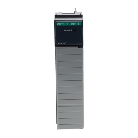
Rockwell Automation Allen-Bradley 1746-HSCE User Manual (115 pages)
4-Channel Analog I/O Modules
Brand:
Rockwell Automation
| Category:
Control Unit
| Size: 4.12 MB
Table of Contents
Table of Contents
6
Preface
10
Who Should Use this Manual
10
Purpose of this Manual
10
Related Documentation
11
Common Techniques Used in this Manual
12
Your Questions or Comments on this Manual
12
Overview
14
How to Use Analog
14
Types of Analog Modules
14
1746-NI4 Analog Input Module
15
1746-NIO4I and NIO4V Analog Combination Modules
15
1746-NO4I and NO4V Analog Output Modules
15
Quick Start for Experienced Users
16
Required Tools and Equipment
16
Procedures
17
Installing and Wiring Your Analog Module
24
European Union Directive Compliance
24
EMC Directives
24
Determining Your Power Requirements for a Modular Controller
25
Determining Your Power Requirements for a Fixed Controller
25
Configuring Your Module
28
Switch Settings for the 1746-NI4
28
Switch Settings for the 1746-NIO4I and -NIO4V
28
External Power Switch for the 1746-NO4I and -NO4V
29
Choosing a Slot in the Chassis
29
Installing Your Module
29
Removing the Analog Module Terminal Block
30
Wiring Considerations
31
System Wiring Guidelines
32
Grounding Your Cable
32
Determining the Cable Length
33
Wiring the Analog Module
33
Labeling and Installing the Terminal Block
35
Grounding the Foil Shields and Drain Wires
35
Wiring Schematics for 2, 3, and 4-Wire Analog Input Devices
37
Wiring Schematic for Single-Ended Analog Input Connections
38
Minimizing Electrical Noise on Analog Modules
38
Interface between the Module and the Processor
40
Entering Module ID Codes
40
Addressing Analog Modules
41
Bit Level Addressing
43
Processor Update of Analog Data
44
Monitoring the Input and Output Data
44
Converting Analog Input Data
45
Converting Analog Output Data
46
System Considerations
48
Safe State for Outputs
48
Retentive Programming Option
48
Retentive Analog Output Example
49
Non-Retentive Analog Output Example
50
During a Mode Change or Power Cycle
50
Input Out-Of-Range Detection
50
Response to Slot Disable
52
Input Response to Slot Disable
52
Output Response to Slot Disable
52
Input Channel Filtering
53
Testing the SLC 500 System
56
Start-Up Procedures
56
Inspect the Analog Module
57
Disconnect Prime Movers (Motion Devices)
57
Power up the SLC 500 System
58
Testing Analog Inputs
59
Testing Analog Outputs
61
Addressing, Out-Of-Range Detection, and Scaling of Analog
64
Inputs
64
Calculating the Linear Relationship
65
Calculating the Out-Of-Range Flag Using the Scale Instruction
66
Using Standard Math
67
Using the Scale (SCL) Instruction
69
Using Scale with Parameters (SCP) Instruction
70
Addressing and Scaling Outputs
71
Calculating the Linear Relationship
71
Using Standard Math
73
Using the Scale with Parameters (SCP) Instruction
75
Scaling Offset When > 32,767 or < -32,768
77
Calculating the Linear Relationship
77
Calculating the Shifted Linear Relationship
78
Using Standard Math
79
Using the Scale with Parameters (SCP) Instruction
81
Scaling and Range Checking and Analog Inputs and Outputs
83
Calculating the Linear Relationship
84
Using Standard Math Instructions
85
Scaling and Range Checking of Analog Inputs and Outputs
87
Using SCL Instruction
88
Using the Scale with Parameters (SCP) Instruction
89
Preventative Maintenance
90
Safety Considerations When Troubleshooting
91
Analog Modules Specification
92
General Specifications for NI4, NIO4I, NIO4V, NO4I, and NO4V
92
Nio4V
93
Current-Loop Input Specifications for NI4, NIO4I, and NIO4V
94
Voltage Input Specifications for NI4, NIO4I, and NIO4V
95
Current Output Specifications for NIO4I and NO4I
96
Voltage Output Specifications for NIO4V and NO4V
97
Positive Decimal Values
98
Negative Decimal Values
99
Calibrating an Analog Input Channel
102
Calculating the Software Calibration
103
Advertisement
Advertisement
Related Products
Rockwell Automation 1746-NO8I
Rockwell Automation 1746-NO8V
Rockwell Automation Allen-Bradley 1746-BTM
Rockwell Automation Allen-Bradley 1746-NI4
Rockwell Automation Allen-Bradley 1746-NIO4I
Rockwell Automation Allen-Bradley 1746-NIO4V
Rockwell Automation Allen-Bradley 1746-NO4I
Rockwell Automation Allen-Bradley 1746-NO4V
Rockwell Automation AB quality Allen-Bradley 1746-INT4
Rockwell Automation Allen-Bradley SLC ControlNet 1747-SCNR
Rockwell Automation Categories
Controller
Control Unit
Power Supply
DC Drives
Industrial Equipment
More Rockwell Automation Manuals
Login
Sign In
OR
Sign in with Facebook
Sign in with Google
Upload manual
Upload from disk
Upload from URL