Sign In
Upload
Manuals
Brands
ROBWAY Manuals
Controller
RCI-4100
ROBWAY RCI-4100 Manuals
Manuals and User Guides for ROBWAY RCI-4100. We have
1
ROBWAY RCI-4100 manual available for free PDF download: Operation And Installation
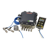
ROBWAY RCI-4100 Operation And Installation (187 pages)
Tension-Based System
Brand:
ROBWAY
| Category:
Controller
| Size: 13 MB
Table of Contents
Table of Contents
3
Important Safety Notices
9
1 System Description
11
General
11
Capabilities
11
Hazardous Area
11
Available Options
11
References
11
Limited Product Warranty
12
Intended Audience
12
Personnel Qualifications
12
2 Installation
13
Setting up the Crane
13
Power Supply
13
Installing Boom Components
13
Boom Angle Sensor (Eex D)
14
Tension Cell Type
15
Single Sheave Dynamometer with Load Pin
16
Telescopic Boom Length Sensor
17
Anti-Two-Block (Optional Item)
18
Cabling (Sensors)
19
Display Unit (Ex Ib)
20
Hazardous Area Control Unit (if Not Safe Area)
20
Setting DIP Switches for Cable Length
21
Cable Glands
22
Safe Area Control Unit (if Not Hazardous Area)
22
Cabling Instructions
23
Earthing
24
Switch Inputs
24
Relay Outputs
24
Motion-Cut Output Rl-1
24
Installing Slew Ring Components
25
Restricted Slew Zone Encoder
25
Proximity Switch (for Optional Restricted Slew Zone Feature)
26
Installing Winch Components
27
Hook Height Winch Encoder
27
3 Operating Instructions
29
Applying Power to the Rci-4100
29
Turning off the Rci-4100
29
Operating Screen
30
Display Functions
31
Alphanumeric Lcd Screen and Alarm Led Indicators
31
4-Digit Lcd Screens
33
ACTIVE WINCH and ATB LED INDICATORS
33
Function Push Buttons
34
Restricted Slew Zone Monitoring - Optional Feature
34
Wind Speed Monitoring - Optional Feature
34
Wind Direction - Optional Feature
34
Gross Over-Moment Protection (GOP) - Optional Feature
34
Tilt Sensing - Optional Feature
35
Hook Height - Optional Feature
35
4 Data Logging and Data Downloading
37
5 Uploading Crane Software Using Sd Card
39
6 Function Code Descriptions
41
Exit Calibration Mode
41
Main Load
41
View Calibrated Main Load
41
Calibrate Light Main Load
41
Calibrate Heavy Main Load
41
Aux Load
41
View Calibrated Aux Load
41
Calibrate Light Aux Load
41
Calibrate Heavy Aux Load
41
Calibrate High Angle
42
Length (Telescopic Cranes Only)
42
View Uncalibrated Length Input
42
View Calibrated Length Input
42
Calibrate Short Length
42
Calibrate Long Length
42
View Uncalibrated Transducer 1 Input
42
View Uncalibrated Transducer 2 Input
42
Offset and Gain Adjustment
42
Set Gain and Offset for Channels 1 to 8
43
Number of Sensor Samples to Average
44
Load Chart View Mode
44
View Digital Inputs
44
Set Year
44
Set Day and Month
44
Set Time
44
Download Logger Contents to Pc or Sd Card
44
Erase Logger Contents
45
Alter Calibration Data
45
Clear All Calibration Data - Use Extreme Caution
46
Main Winch Slack Rope Threshold
46
Aux Winch Slack Rope Threshold
46
User Variables (SWL % Alarms, Motion Cut)
46
User Variables (Crane Geometry)
46
User Variables (Data Logging Setup Parameters)
46
Load / Angle Correction
46
Main Winch Rigging Swl
47
Auxiliary Winch Rigging Swl
47
Boom Height Offset
47
Metric/Imperial Units Switching
47
Time Delay for Motion Cut Return
47
Slew Encoder (if Applicable)
47
View Slew Encoder Raw Counts
47
Counts Per 360Deg Slewing of Crane
47
Slew Encoder Direction
47
Hoist Rope Friction Compensation
47
7 Calibration
49
Calibration Mode
49
Entering Calibration Mode
49
Using Calibration Functions
49
Tools/Items Required for Calibration
50
Map of Calibration (Suggested Order)
50
Calibration Procedure
50
Check/Set Year, Day/Month and Time
51
Check / Set the Following
51
Configuring User Variables
51
Verifying Operation of Sensors
51
Calibrating Boom Angle
52
Calibrating Load on the MAIN Winch (Without Friction Compensation)
53
Calibrating Load on the AUX Winch (Without Friction Compensation)
53
Calibrating Load on the MAIN Winch (with Friction Compensation)
54
Calibrating Load on the AUX Winch (with Friction Compensation)
54
Using Load/Angle Correction Function
55
Set Main Winch Rigging SWL
56
Set Aux Winch Rigging SWL
56
Slew Encoder Operation (if Installed)
56
Testing the Slack Rope Function
56
Post Calibration Checks
57
8 Troubleshooting
59
Example Problems and Possible Causes
60
Problems that Produce Error Codes
60
Error Codes Summary
62
Problems that Do Not Produce Error Codes
63
Problems with Digital Inputs, Digital Outputs and Relay Outputs
64
Description of Digital Inputs, Digital Outputs and Relay Outputs
64
What Are the Inputs and Outputs on this Crane
64
Troubleshooting Digital Inputs
65
Troubleshooting Digital Outputs
66
Troubleshooting Relay Outputs
67
Sensor Replacement
68
Fuse Replacement
69
9 Inspection
71
Pre-Installation
71
Post-Installation
72
Post-Commissioning
72
Detailed Inspection
72
Periodic Inspection
73
Visual Inspection from Floor Level
73
Inspection and Test Schedule
74
10 Maintenance
75
Checklist
75
Removal of Electrical Equipment
75
Maintenance Work in Hazardous Areas
76
Maintenance Work in Non-Hazardous Areas
76
Modification or Repair
76
Inspection after Maintenance
76
Records
76
Printed Circuit Board (Pcb) Handling
76
Cufrci4100 Flameproof Controller Mating Surfaces Precautions
76
11 General Specifications
77
Advertisement
Advertisement
Related Products
ROBWAY Categories
Controller
More ROBWAY Manuals
Login
Sign In
OR
Sign in with Facebook
Sign in with Google
Upload manual
Upload from disk
Upload from URL