Table of Contents
Advertisement
Advertisement
Table of Contents
Troubleshooting

Summary of Contents for ROBWAY RCI-4100
- Page 1 RCI-4100 Tension-Based System Operation and Installation SINGLE / TWIN WINCH STRUT BOOM CRANE MAN-1111 Rev H LSI-Robway Pty Limited, 32 West Thebarton Road, Thebarton, South Australia, 5031 Phone: +61 (0) 8 8238 3500 Fax: +61 (0) 8 8352 1684 www.lsirobway.com.au...
-
Page 3: Table Of Contents
ROTECTION PTIONAL EATURE 3.9......................35 ENSING PTIONAL EATURE 3.10. – O .......................35 EIGHT PTIONAL EATURE DATA LOGGING AND DATA DOWNLOADING ..................37 UPLOADING CRANE SOFTWARE USING SD CARD ................39 FUNCTION CODE DESCRIPTIONS ......................41 MAN-1111 Rev H ©Copyright 2015 LSI-Robway Pty Ltd... - Page 4 ALIBRATION ROCEDURE 7.4.1. Check/set year, day/month and time.....................51 7.4.2. Check / Set the following: ........................51 7.4.3. Configuring User Variables .........................51 7.4.4. Verifying Operation of Sensors ......................51 7.4.5. Calibrating Boom Angle ........................52 MAN-1111 Rev H ©Copyright 2015 LSI-Robway Pty Ltd...
- Page 5 ........................76 ODIFICATION OR EPAIR 10.6......................76 NSPECTION AFTER AINTENANCE 10.7..............................76 ECORDS 10.8. (PCB) H .....................76 RINTED IRCUIT OARD ANDLING 10.9. CUFRCI4100 F ...........76 LAMEPROOF ONTROLLER ATING URFACES RECAUTIONS GENERAL SPECIFICATIONS ........................77 MAN-1111 Rev H ©Copyright 2015 LSI-Robway Pty Ltd...
- Page 7 RCI-4100 Declaration of Conformity updated to RCI-4100 Declaration Rev G. 20Aug12 Revised Sections 2 to 8. Added Appendices J and H. Various minor changes. RCI-4100 Declaration of Conformity updated to Rev H. RF Transmitter Caution added. 14Jan14 Company Name Change...
-
Page 9: Important Safety Notices
THE RCI-4100IS SYSTEM IS INTENDED FOR USE IN A GROUP IIB ZONE 1 EXPLOSIVE GAS ATMOSPHERE. WARNING: THE RCI-4100 SYSTEM IS A CRANE DEVICE WHICH WARNS THE OPERATOR OF IMPENDING OVERLOAD CONDITIONS AND OVER-HOIST CONDITIONS WHICH COULD CAUSE DAMAGE TO PROPERTY, CRANE AND PERSONNEL. - Page 10 SPECIFICATIONS. OBTAIN SPECIALIST ASSISTANCE WHEREVER APPLICABLE. CAUTION: RADIO FREQUENCY EMITTING EQUIPMENT SHOULD NOT BE PLACED NEAR THE RCI-4100 CONTROLLER, DISPLAY, CABLING OR SENSORS AS IT MAY CAUSE INTERFERENCE DEPENDING ON THE TYPE, POWER OUTPUT AND OTHER CHARACTERISTICS OF THE EQUIPMENT. MAN-1111 Rev H ©Copyright 2015 LSI-Robway Pty Ltd...
-
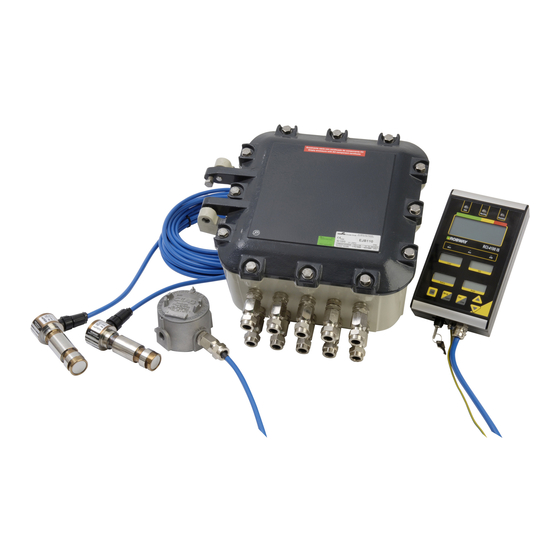
Page 11: System Description
This manual contains general information, installation, operation, calibration, maintenance and fault- finding information for the RCI-4100 Rated Capacity Indicating System to suit a Strut Boom Crane using Tension Based Load Measurement with one or more system components located in a hazardous area. -
Page 12: Limited Product Warranty
Any LSI-Robway product that has been repaired or altered in such a way, in LSI-Robway judgement, as to affect the product adversely, including installation methods and procedures, negligence, accident or improper storage or use will be judged solely by LSI-Robway in regard to any partial or full warranty claim. -
Page 13: Installation
POSITION. 2.2. Power Supply The RCI-4100 can be powered by a 10.5 VDC to 36 VDC supply. The selected power supply may be permanently connected, however for convenience it should be made via an ON/OFF switch or relay. If the Control Unit is located within a hazardous area, the power MUST be supplied via steel wire armoured cable in accordance with local installation standards. -
Page 14: Boom Angle Sensor (Eex D)
ANGES4130 IN A HAZARDOUS ZONE. LOCAL INSTALLATION GUIDELINES GOVERNING SAFE AREA CIRCUITS TRAVERSING HAZARDOUS ZONES MUST BE FOLLOWED. THE CABLE MUST BE PROTECTED FROM MECHANICAL DAMAGE; LSI-ROBWAY SUPPLIES AN ARMOURED CABLE WITH EPOXY EX D GLAND SEALING KITS FOR THIS PURPOSE. MAN-1111 Rev H ©Copyright 2015 LSI-Robway Pty Ltd... -
Page 15: Tension Cell Type
A tension plate-type load cell may be fitted at the hoist rope dead-end of the boom tip section to sense the hoist line-pull. LSI-Robway tension cells can be supplied with standard “side plates” (or “sister plates”) to provide extra protection against extreme twisting during crane operation. -
Page 16: Single Sheave Dynamometer With Load Pin
Max line-pull is 25 tonnes + test allowance = 25.0 + 15% = 32.5t Calculation: - Sin (2.7 deg) x 32.5t = 1.53t down force This is an intrinsically safe circuit so “blue sheathed” cable supplied by LSI-Robway is required. CAUTION: HIGH TENSILE BOOMS REQUIRE PROPER WELDING PROCEDURE SPECIFICATIONS. -
Page 17: Telescopic Boom Length Sensor
When booms deflect and pads wear the cable will take up a lower position in the eye. Stainless steel cable ties are also supplied with the installation kit and to be used where required. MAN-1111 Rev H ©Copyright 2015 LSI-Robway Pty Ltd Page 17... -
Page 18: Anti-Two-Block (Optional Item)
OPERATION AND INSTALLATION RCI-4100 SYSTEM This is an intrinsically safe circuit so “blue sheathed” cable supplied by LSI-Robway is required. Anti-Two-Block (Optional Item) 2.3.5. (Wired to Control Unit though an EEx ib Digital Switch Isolating Barrier) Fix the anti-two-block (ATB) switch mounting pin to the main boom head preferably so that the bob- weight (when suspended from the switch) can be fitted to the static hoist rope below the rope anchor. -
Page 19: Cabling (Sensors)
Blue jacketed cable must not be used for non I/S circuits. Boom Angle Sensor cable must be “LSI-Robway-supplied” 4 core steel wire armoured cable (not blue). UV shield socking may be fitted. -
Page 20: Display Unit (Ex Ib)
When opening the Controller housing it is critical that any water caught in the bolt holes is not allowed to enter the controller. This will likely lead to water damage which is not covered by LSI-Robway warranty. Wherever possible the Controller housing should be mounted vertically to prevent moisture pooling problems in the base of the controller. -
Page 21: Setting Dip Switches For Cable Length
If the cable length is greater than 5 metres up to 10 metres in length then the 10 meter switch (SW1) is set to “ON” and switches SW2 and SW3 are set to “OFF”. Figure 7 - DIP Switches for Cable Length - CIRPCB4163 MAN-1111 Rev H ©Copyright 2015 LSI-Robway Pty Ltd Page 21... -
Page 22: Cable Glands
The enclosure has overall outside dimensions of 275mm (H) x 350mm (W) x 200mm (D) with an environmental protection of IP65. The Control Unit contains the termination points for all modules within the RCI-4100 system. Terminate all connection cables at the Control Unit. -
Page 23: Cabling Instructions
Within the enclosure, ensure that a 50mm separation exists between “safe area circuit” terminals and “intrinsically safe circuit” terminals. Do not coil excess display cable outside or within the RCI-4100 enclosure – always cut off excess cable. Blue-jacketed cable commonly denotes an “intrinsically-safe circuit” when located in a hazardous zone. -
Page 24: Earthing
Reference the applicable drawing(s) in RCI System Configuration Documents in Attachments. 2.5. Relay Outputs The RCI-4100 Control Unit has three (3) safety relays on board the PCB and up to another eight (8) switching relays on the terminal block. The safety relays have voltage-free contact rated to 5A and are only used to energise the coils of external high-power SLAVE relays such as motion cut, slack rope detect output, boom up motion cut (minimum radius limit), etc. -
Page 25: Installing Slew Ring Components
Refer to APPENDIX H, Restricted Slew Zone Monitoring Option Figure 7 - Slew encoder (NOTE: Encoder shown is for illustration only; actual encoder supplied may differ in model and type.) MAN-1111 Rev H ©Copyright 2015 LSI-Robway Pty Ltd Page 25... -
Page 26: Proximity Switch (For Optional Restricted Slew Zone Feature)
(see typical installation below). LSI-Robway recommends that this switch be located so that it corresponds with the rest position of the crane so that the slew system is reset on every crane start-up. -
Page 27: Installing Winch Components
Figure 10 - Winch encoder (NOTE: Encoder shown is for illustration only; actual encoder supplied may differ in model and type.) Refer APPENDIX M, Hook Height Option for further information and calibration instructions. MAN-1111 Rev H ©Copyright 2015 LSI-Robway Pty Ltd Page 27... -
Page 29: Operating Instructions
The following sections explain how to operate the RCI-4100 and make best use of its capabilities. 3.1. Applying power to the RCI-4100 As soon as power is applied to the RCI-4100, its display and other indicators should light up and the RCI-4100 should go through its self-test operation. -
Page 30: Operating Screen
OPERATION AND INSTALLATION RCI-4100 SYSTEM 3.3. Operating Screen The following is the operating screen of the RCI-4100 showing the general display functions: LED Indicator Lamps for Safe, Warning and Overload/Fault Alphanumeric LCD Conditions screen showing various functions (SWL Bargraph, Duty... -
Page 31: Display Functions
RCI-4100 SYSTEM 3.4. Display Functions The RCI-4100 display is comprised of one 4x16 alphanumeric LCD, four 4-digit LCD’s, three alarm LED’s, three indicator LED’s and five push buttons. The functions of these are as follows: ALPHANUMERIC LCD SCREEN AND ALARM LED INDICATORS 3.4.1. - Page 32 Operation of this key is for authorized personnel only who shall be solely responsible for its use. Note: LSI-Robway recommends that the over-ride key switch be switched OFF at all times and the over-ride key switch be held by the site-supervisor or another authorized person.
-
Page 33: 4-Digit Lcd Screens
Illuminated when two-blocking condition is detected, at which point the Red-Overload LED at the top of the display will also illuminate, activating the continuous audible alarm and ATB motion cut relay. MAN-1111 Rev H ©Copyright 2015 LSI-Robway Pty Ltd Page 33... -
Page 34: Function Push Buttons
3.6. Wind Speed Monitoring – Optional Feature Wind Speed Monitoring is an optional feature that can be integrated into the RCI-4100 system if required. If this option is supplied, please refer to APPENDIX I, Wind Speed Monitoring Option for usage information and details. -
Page 35: Tilt Sensing - Optional Feature
3.9. Tilt Sensing - Optional Feature Tilt sensing option is an optional feature that can be integrated into the RCI-4100 system if required. This option provides a tilt indication and can also be configured to supply alarms at pre-determined points and/or switch load charts at pre-determined points. -
Page 37: Data Logging And Data Downloading
Where F-xx appears please determine relevant function code numbers. The RCI-4100 Control Unit has an on-board SD card to which data from the internal data logger can be downloaded and saved for reading on a PC. The internal logger records all data within the set parameters of the logger and system. The data are stored in the on-board flash memory chip. - Page 38 OPERATION AND INSTALLATION RCI-4100 SYSTEM MAN-1111 Rev H ©Copyright 2015 LSI-Robway Pty Ltd Page 38...
-
Page 39: Uploading Crane Software Using Sd Card
RCI-4100 SYSTEM Uploading Crane Software Using SD Card The crane software can be uploaded into the CPU of the RCI-4100 Control Unit using the SD card. Figure 12 - RCI-4100 Control Unit board showing the SD card slot During normal operation, the system reads and processes data from the CPU and not from the SD card. - Page 40 Complete recalibration of the system is now required. Refer to “Section 7 Calibration” for the • calibration procedure. Please contact LSI-Robway for further details and assistance on the dummy software. • CAUTION: CHANGING THE SOFTWARE WILL CHANGE THE OPERATION OF THE RCI- 4100 AND IT IS MOST IMPORTANT THAT THE CORRECT SOFTWARE CORRESPONDING TO THE CRANE IS USED ON EACH CRANE.
-
Page 41: Function Code Descriptions
Refer to for Function Code numbers for the RCI-4100 system. Take great care to ensure that the function code numbers are checked against this Function Code List. Note: The following function codes are listed for explanation and may not be used in every RCI- 4100software. -
Page 42: Calibrate High Angle
What is offset? LSI-Robway analogue input channels are not designed to start at zero signal level, this is to allow for sensor error detection. Because of this offset, amplification factors would have to be limited to ensure that the high end doesn’t exceed available raw counts. So if a software offset is introduced to MAN-1111 Rev H ©Copyright 2015 LSI-Robway Pty Ltd... -
Page 43: Set Gain And Offset For Channels 1 To 8
Software gain level is settable via function codes (as a number) from 1 (no amplification input=output) up to 1023 (maximum amplification). LSI-Robway uses different types of load sensors and they can have different levels of output. For example a load pin has 1mV/V output and tension plate cells generally have 2mV/V output. -
Page 44: Number Of Sensor Samples To Average
6.10. Load Chart View Mode This function code can be used to view the load charts programmed in the software. It is not part of the calibration or set-up procedures. It is mainly used by LSI-Robway for software checking. 6.11. View Digital Inputs This function code is used to view the state (i.e. -
Page 45: Erase Logger Contents
Figure 14 – Example Table to Record Calibration Data Restoring Calibration Data Restoring the calibration data requires entering the calibration data copied from the procedure above using the same function code. MAN-1111 Rev H ©Copyright 2015 LSI-Robway Pty Ltd Page 45... -
Page 46: Clear All Calibration Data - Use Extreme Caution
Repeat this procedure for other sensors as required. 6.18. Clear All Calibration Data – USE EXTREME CAUTION! Activating this function will clear all the calibration data. This must only be used by LSI-Robway-trained personnel for troubleshooting purposes. The display will prompt the operator to press ENTER if he wishes to erase the calibration data. -
Page 47: Main Winch Rigging Swl
The following variables are provided to ensure accurate counting of the slew encoder to provide correct slew angle. A proximity switch is normally used provide a reset position in the event that the crane is slewed when the RCI-4100 is switched off. View Slew Encoder Raw Counts 6.30.1. - Page 48 Note that all tension based systems have this feature. Two calibration procedures, one without friction compensation, and one using friction compensation (for both Main and Aux) are detailed in Section 7 Calibration. Refer Sections 7.4.6 to 7.4.9. MAN-1111 Rev H ©Copyright 2015 LSI-Robway Pty Ltd Page 48...
-
Page 49: Calibration
Make sure that the correct duty number (crane configuration, sea state) and falls (parts of line) • are selected, Insert the over-ride key into the RCI-4100 Display and turn it on, make sure that the over-ride • indicator (O/R) is shown on the display, Press and hold the SETUP button for about 2 seconds, •... -
Page 50: Tools/Items Required For Calibration
RCI-4100 will report an error and activate motion cut. To prevent this you can press the ENTER key, while in "VIEW UNCALIBRATED TRANSDUCER 2 function", to turn the auxiliary channel off. -
Page 51: Check/Set Year, Day/Month And Time
RCI-4100 at the time of manufacture. As this information may vary from crane to crane, even if they are of the same model, the RCI-4100 allows the installer to change these variables on site. These user variables include dimensions such as slew-offset, maximum falls for main/aux winches, maximum line- pulls, sheave diameters, etc. -
Page 52: Calibrating Boom Angle
Tip: raw counts should be approximately 2000 when boom is at 45 deg. If the sensors check out then you can continue with the calibration procedure. If any problems are found refer to Section 8. “Troubleshooting or seek help from your nearest LSI-Robway representative. Calibrating Boom Angle 7.4.5. -
Page 53: Calibrating Load On The Main Winch (Without Friction Compensation)
Use the UP/DOWN keys to ramp the display to the required value (calculated heavy load ). Press ENTER to accept value. Step 3) Verify that the AUX Load Calibration Use the “VIEW CALIBRATED AUX LOAD” function code. MAN-1111 Rev H ©Copyright 2015 LSI-Robway Pty Ltd Page 53... -
Page 54: Calibrating Load On The Main Winch (With Friction Compensation)
Use the UP/DOWN keys to ramp the display to the required value (i.e., calculated light load above). Start hoisting the load up slowly. Press ENTER to accept value. Stop hoisting. Select “Calibrate Light Aux Load”. MAN-1111 Rev H ©Copyright 2015 LSI-Robway Pty Ltd Page 54... -
Page 55: Using Load/Angle Correction Function
The correction factor is simply the difference between the two load values you have recorded. Enter the correction value against the appropriate Function Code and luff the crane through its operating range once again to ensure the correction was successful. Example: MAN-1111 Rev H ©Copyright 2015 LSI-Robway Pty Ltd Page 55... -
Page 56: Set Main Winch Rigging Swl
Aux block using the appropriate function code. This setting will enable the function to operate when the load on either block gets lower than its weight (i.e., slack condition). MAN-1111 Rev H ©Copyright 2015 LSI-Robway Pty Ltd Page 56... -
Page 57: Post Calibration Checks
PLEASE NOTE THAT ALL INDUCTIVE LOADS SUCH AS RELAYS AND SOLENOIDS REQUIRE SNUBBER DIODES FOR TRANSIENT SUPPRESSION. 7.5. Post Calibration Checks After completing the calibration check all functions of the RCI-4100 including: Displayed radius for accuracy. • Lift some test weights on main and aux winches to ensure accuracy. -
Page 59: Troubleshooting
The main purpose of this section is to help both us at LSI-Robway and you the reader to find the problem and solve it quickly. -
Page 60: Example Problems And Possible Causes
• The signal - is connected to the shield. • The signal + and the excitation + are swapped. • The signal - and the excitation - are swapped. • MAN-1111 Rev H ©Copyright 2015 LSI-Robway Pty Ltd Page 60... - Page 61 Error Code -999 This indicates an invalid calibration Possible causes: Low and high end of sensor calibrated to same raw counts. • Sensor needs to be re-calibrated to clear this error MAN-1111 Rev H ©Copyright 2015 LSI-Robway Pty Ltd Page 61...
-
Page 62: Error Codes Summary
00C0000000 would be a 240 and a 280 at the same time 00C0000000 would be a 240 and a 280 at the same time 00000F0000 would be a 301, 302, 304 and 308 at the same time. MAN-1111 Rev H ©Copyright 2015 LSI-Robway Pty Ltd Page 62... -
Page 63: Problems That Do Not Produce Error Codes
ENTER button again until the display gets into the normal initialisation/ set-up routine and then to normal operating mode. Note that this will clear the data log of all entries. MAN-1111 Rev H ©Copyright 2015 LSI-Robway Pty Ltd Page 63... -
Page 64: Problems With Digital Inputs, Digital Outputs And Relay Outputs
Description of Digital Inputs, Digital Outputs and Relay Outputs. 8.2.1. Digital Inputs Digital inputs provide switched inputs to the RCI-4100. Digital switched inputs can be used for a wide range of uses. Examples are (but not limited to): Proximity switches (slew reset, hoist direction, boom angle limit). -
Page 65: Troubleshooting Digital Inputs
Refer RCI System Configuration Documents in Attachments to identify digital inputs used on this crane. To confirm that a digital input is being switched, open the RCI-4100 controller and check that the applicable digital input LED on the controller PCB is illuminated. Figure 16 shows location of digital input LEDs. -
Page 66: Troubleshooting Digital Outputs
Refer RCI System Configuration Documents in Attachments to identify digital outputs used on this crane. To confirm the state of a digital output, open the RCI-4100 controller and check the applicable digital output LED on the controller PCB. Figure 17 shows location of digital output LEDs. -
Page 67: Troubleshooting Relay Outputs
Figure 18 - RCI-4100 Controller PCB showing location of Relay Outputs (RL) Connectors Relay LED indications: • If the applicable relay status indicates that the relay is in the incorrect state confirm that the RCI-4100 • operating conditions are correct (check applicable digital inputs, displayed radius, angle, main and aux load). -
Page 68: Sensor Replacement
Any other type of sensor should be checked for displayed accuracy at least at one reading, two if • possible and sensor re-calibration procedure should be completed if accuracy is not within (regulatory, site, operator or owner) acceptable accuracy. MAN-1111 Rev H ©Copyright 2015 LSI-Robway Pty Ltd Page 68... -
Page 69: Fuse Replacement
OPERATION AND INSTALLATION RCI-4100 SYSTEM 8.4. Fuse Replacement If a fuse is found to be blown refer to the picture below for fuse labels, locations and specifications: Figure 19 - RCI-4100 Controller PCB showing location of Fuses Fuse Specifications: Current/Voltage Rating Size... -
Page 71: Inspection
The certificate number of the system. 9.1.3. A list of all uncertified items used in the installation. With the RCI-4100 IS system, for example, uncertified items are loadcells, simple switches, junction boxes and potentiometer type sensors. All these items are classified by the standard as simple apparatus and do not require certification. -
Page 72: Post-Installation
Where these modifications were performed by a party other than LSI-Robway, these justifications must be supplied by those responsible for such modifications. LSI- Robway takes no responsibility for modifications done to the system that have not been authorised by LSI-Robway in written form. -
Page 73: Periodic Inspection
"Visual" column in the Inspection and Test Schedule, with an interval which must not exceed half the Periodic Inspection interval. For all inspections, the results must be recorded. MAN-1111 Rev H ©Copyright 2015 LSI-Robway Pty Ltd Page 73... -
Page 74: Inspection And Test Schedule
Equipment is adequately protected against corrosion, moisture, vibration, excessive temperature, and other adverse factors. Installation compliance with documentation. In the above chart, A=All, S=Sample and N=Not required by the standard, but sample is recommended. MAN-1111 Rev H ©Copyright 2015 LSI-Robway Pty Ltd Page 74... -
Page 75: Maintenance
10. Maintenance When maintenance is to be performed on the RCI-4100 system, care must be taken to ensure that the level of safety is not reduced. Such a reduction in the level of safety can easily be done by the careless use of tools or test equipment, either directly or by damage to safety components, wiring or clearances. -
Page 76: Maintenance Work In Hazardous Areas
Ensure that that dates of all inspections, tests, maintenance, and defects are recorded. 10.8. Printed Circuit Board (PCB) Handling If the RCI-4100 controller PCB is removed for any reason anti-static precautions must be employed. 10.9. CUFRCI4100 Flameproof Controller Mating Surfaces Precautions The mating surfaces between housing and cover of the CUFRCI4100 flameproof controller must be kept clean and damage free. -
Page 77: General Specifications
Audible Alarm: Piezo ceramic buzzer Intermittent – approach to SWL or over-ride active Continuous – overload and/or error(s) Text Messages: Alphanumeric Alarm/Error conditions Over-ride Feature Over-ride key switch on Display Unit MAN-1111 Rev H ©Copyright 2015 LSI-Robway Pty Ltd Page 77... - Page 78 Option for Ex ia, Zone 1 interface or safe area Configurable: State (e.g. proximity switch) Quadrature (e.g. slew) Accumulator (e.g. event counter) Frequency (e.g. wind speed) Open circuit switch voltage: approx. 3 VDC Closed circuit switch current: 3 mA MAN-1111 Rev H ©Copyright 2015 LSI-Robway Pty Ltd Page 78...
- Page 79 Up to 32 GByte can be accommodated Program upload/download Calibration upload/download Logged Data download System Microprocessor Watchdog Onboard Timekeeping with power backup Automatic System Diagnostics On-board Calibration System Calibration via Operator Console MAN-1111 Rev H ©Copyright 2015 LSI-Robway Pty Ltd Page 79...
- Page 80 Operating Temperature -20°C to +60°C Dust and Water Ingress, IP65 Control Unit with Ex d Housing: Operating Temperature -20°C to +60°C Dust and Water Ingress IP65 61000-6-4 61000-6-2 RoHS Compliant RoHS Compliant MAN-1111 Rev H ©Copyright 2015 LSI-Robway Pty Ltd Page 80...
- Page 81 SAFETY AND INSTALLATION INSTRUCTIONS RCI-4100 DISPLAY AND ISOLATING BARRIER SYSTEM APPENDIX A, Safety and Installation Instructions, Model 4120 RCI- 4100IS Display Barrier MAN-1111 Rev H ©Copyright 2015 LSI-Robway Pty Ltd Page 81...
- Page 83 SAFETY AND INSTALLATION INSTRUCTIONS RCI-4100 DISPLAY AND ISOLATING BARRIER SYSTEM Safety and Installation Instructions Model 4120 RCI-4100 Display Barrier LSI-Robway Pty Limited 32 West Thebarton Road Thebarton, SA 5031 Australia +61 8 8238 3500 www.lsiRobway.com.au MAN-1111 Rev H ©Copyright 2015 LSI-Robway Pty Ltd...
- Page 84 Although longer interconnecting cable runs may function satisfactorily LSI-Robway does not warrant the system working with a longer interconnecting cable than that supplied. In addition, if the interconnecting cable is to be extended beyond what is supplied the capacitance and inductance values must not exceed the limits given.
- Page 85 RCI-4100 DISPLAY AND ISOLATING BARRIER SYSTEM OPERATION The LSI-Robway Model 4100 Display is intended to be used with the Model 4120 Display Barrier. The Model 4120 Barrier provides isolated power to the Model 4100 display and also an isolated intrinsic safety barrier for I2C communications from a host data system located in a safe area.
- Page 86 SAFETY AND INSTALLATION INSTRUCTIONS RCI-4100 DISPLAY AND ISOLATING BARRIER SYSTEM 4100 Display Power/Data Wiring Detail 4100 DISPLAY TO BARRIER WIRING Barrier 4120 Isolating Conductor 4100 Display Display Description Barrier Terminal Colour Terminal Description Supply- Black Supply+. Green White STARTUP Before applying power to the system check that all wires are properly connected, particularly supply conductors and their polarity, and serial data wires.
- Page 87 SAFETY AND INSTALLATION INSTRUCTIONS RCI-4100 DISPLAY AND ISOLATING BARRIER SYSTEM INSTALLATION CONTROL DRAWING MAN-1111 Rev H ©Copyright 2015 LSI-Robway Pty Ltd Page 87...
- Page 89 SAFETY AND INSTALLATION INSTRUCTIONS RCI-4100 DISPLAY AND ISOLATING BARRIER SYSTEM 4100 Display Compliance IECEx Certificate Number ITA 08.0021X Ex ib, Group IIB ATEX Certificate Number NEMKO 08 ATEX 1433X Temperature Classification T4, -20°C < Tamb <+60°C RoHS Product Markings ATEX Ex ib IIB/IIA T4 -20°C <...
- Page 90 SAFETY AND INSTALLATION INSTRUCTIONS RCI-4100 DISPLAY AND ISOLATING BARRIER SYSTEM 4120 Isolating Barrier Compliance IECEx Certificate Number ITA 08.0020X Ex ib, Group IIB ATEX Certificate Number NEMKO 08 ATEX 1433X [EEx ib] IIB Temperature Classification T4, -20°C < Tamb <+60°C...
- Page 91 IECEx ITA 08.0020X IECEx Certificate of Conformity for Barrier Module Type BAREX4120 IECEx ITA 08.0021X IECEx Certificate of Conformity for Display Module Type RCI-4100 IS NEMKO 08 ATEX 1433 X ATEX Type Examination Certificate for Hazardous Areas NEMKO 09 ATEX 4069 Q...
- Page 93 DECLARATION OF CONFORMITY RCI-4100 SYSTEM APPENDIX B, Declaration of Conformity, RCI-4100IS Hazardous Area Rated Capacity Indicator System MAN-1111 Rev H ©Copyright 2015 LSI-Robway Pty Ltd Page 93...
- Page 95 DECLARATION OF CONFORMITY RCI-4100 SYSTEM MAN-1111 Rev H ©Copyright 2015 LSI-Robway Pty Ltd Page 95...
- Page 96 DECLARATION OF CONFORMITY RCI-4100 SYSTEM MAN-1111 Rev H ©Copyright 2015 LSI-Robway Pty Ltd Page 96...
- Page 97 DECLARATION OF CONFORMITY RCI-4100 SYSTEM MAN-1111 Rev H ©Copyright 2015 LSI-Robway Pty Ltd Page 97...
- Page 98 DECLARATION OF CONFORMITY RCI-4100 SYSTEM MAN-1111 Rev H ©Copyright 2015 LSI-Robway Pty Ltd Page 98...
- Page 99 DECLARATION OF CONFORMITY RCI-4100 SYSTEM MAN-1111 Rev H ©Copyright 2015 LSI-Robway Pty Ltd Page 99...
- Page 101 ATEX CERTIFICATE 4100 DISPLAY AND DISPLAY BARRIER APPENDIX C, ATEX EC Type-Examination Certificate MAN-1111 Rev H ©Copyright 2015 LSI-Robway Pty Ltd Page 101...
- Page 103 ATEX CERTIFICATE 4100 DISPLAY AND DISPLAY BARRIER MAN-1111 Rev H ©Copyright 2015 LSI-Robway Pty Ltd Page 103...
- Page 105 IECEX CERTIFICATE RCI-4100IS DISPLAY APPENDIX D, IECEX Certificate of Conformity, Display Module Type RCI-4100IS MAN-1111 Rev H ©Copyright 2015 LSI-Robway Pty Ltd Page 105...
- Page 107 IECEX CERTIFICATE RCI-4100IS DISPLAY MAN-1111 Rev H ©Copyright 2015 LSI-Robway Pty Ltd Page 107...
- Page 109 IECEX CERTIFICATE MODEL 4120 POWER SUPPLY AND I2C BARRIER APPENDIX E, IECEX Certificate of Conformity, Model 4120 Power Supply and I2C Barrier MAN-1111 Rev H ©Copyright 2015 LSI-Robway Pty Ltd Page 109...
- Page 111 IECEX CERTIFICATE MODEL 4120 POWER SUPPLY AND I2C BARRIER MAN-1111 Rev H ©Copyright 2015 LSI-Robway Pty Ltd Page 111...
- Page 113 DATA LOGGING DESCRIPTION APPENDIX F, Data Logging MAN-1111 Rev H ©Copyright 2015 LSI-Robway Pty Ltd Page 113...
- Page 115 Datalog Error Codes Introduction The RCI-4100 data logging occurs automatically whenever the driver lifts a load, whenever the RCI-4100 detects an error condition on the crane such as moving outside the load chart or whenever the over-ride key switch is operated. The installer has the option to set the percentage of SWL a load must reach before the load will be logged.
- Page 116 However, since the logger was recording during calibration it may be desirable to erase the logger contents after completing the angle and load calibrations on the RCI-4100 since the logger would have recorded some invalid information during the calibration of the sensors.
- Page 117 Code, or • The SWL drops to 0 initiating a Type 2 Log cycle. In either case, the currently performed log will be stored prior to initiating a new cycle. MAN-1111 Rev H ©Copyright 2015 LSI-Robway Pty Ltd Page 117...
- Page 118 Because the crane is now back in a safe condition, a new logging cycle begins. When the driver finally puts this load down (assuming he does not luff off the chart again) the normal log cycle completes and another log is written to the logger. MAN-1111 Rev H ©Copyright 2015 LSI-Robway Pty Ltd Page 118...
- Page 119 It should be noted that if motion cut is connected and the display is not in over-ride, luffing to the outer radius limits of the load chart could cause the crane to oscillate as motion cut activates. In this case many logs may be recorded. MAN-1111 Rev H ©Copyright 2015 LSI-Robway Pty Ltd Page 119...
- Page 120 DATA LOGGING DESCRIPTION Example Lift Cycles MAN-1111 Rev H ©Copyright 2015 LSI-Robway Pty Ltd Page 120...
- Page 121 The operator can use two more Function codes for accessing the information stored in the data logger. These Function codes are used for: • Downloading the data logger records to a PC or to an SD card fitted to the RCI-4100 controller SD card holder. Erasing the content of the data logger •...
- Page 122 “LDATA” If this occurs the user must erase the logger contents. To erase contents in this event the over-ride key switch must be switched and “Enter” button pressed until normal display start-up resumes. MAN-1111 Rev H ©Copyright 2015 LSI-Robway Pty Ltd Page 122...
- Page 123 DATA LOGGING DESCRIPTION Detailed Instructions to Download Data Log using SD Card. The RCI-4100 Control Unit has an on-board SD card to which data from the internal data logger can be downloaded and saved for reading on a PC. First, the internal logger records all data within the set parameters of the logger and system. The data is then stored in the on-board flash memory chip.
- Page 124 Radio Receiver not responding Radio Rx Comms Radio Transmitter not responding Tx Comms Fail Radio Transmitter battery failure Tx Low Battery Radio Transmitter short-circuit Tx ATB Short IIC device error IIC Device Error MAN-1111 Rev H ©Copyright 2015 LSI-Robway Pty Ltd Page 124...
- Page 125 D=13, E=14, F=15 etc. Eg: 00C0000000 would be a 240 and a 280 at the same time 00000F0000 would be a 301, 302, 304 and 308 at the same time. MAN-1111 Rev H ©Copyright 2015 LSI-Robway Pty Ltd Page 125...
- Page 127 EX D BARRIER GLAND INSTALLATION INSTRUCTIONS APPENDIX G, Cable Gland Installation Instructions MAN-1111 Rev H ©Copyright 2015 LSI-Robway Pty Ltd Page 127...
- Page 129 EX D BARRIER GLAND INSTALLATION INSTRUCTIONS MAN-1111 Rev H ©Copyright 2015 LSI-Robway Pty Ltd Page 129...
- Page 131 RESTRICTED SLEW ZONE MONITORING APPENDIX H, Restricted Slew Zone Monitoring Option MAN-1111 Rev H ©Copyright 2015 LSI-Robway Pty Ltd Page 131...
- Page 133 The following sections explain how to set and operate the Restricted Slew Zone Controller and make best use of its capabilities. This RCI-4100 has an integrated Restricted Slew Zone (RSZ) controller designed to warn the operator of an impending collision between the crane boom and a fixed structure/obstacle.
- Page 134 No-Go) Boom slew angle Press UP or DOWN arrow key again to enter RSZ setup mode (see next Section "Setting Up Zones). Press SETUP/CANCEL key to return to RCI mode MAN-1111 Rev H ©Copyright 2015 LSI-Robway Pty Ltd Page 134...
- Page 135 "over-ride" key. The temporary set can be accessed and edited by the operator freely. The system will monitor both sets continuously and will work out combined safety restrictions. MAN-1111 Rev H ©Copyright 2015 LSI-Robway Pty Ltd Page 135...
- Page 136 Unite left Merge an unsafe zone to the adjacent unsafe zone to the left "Unite R" Unite right Merge an unsafe zone to the adjacent unsafe zone to the right MAN-1111 Rev H ©Copyright 2015 LSI-Robway Pty Ltd Page 136...
- Page 137 E310 will also be shown on screen. Error Code The RSZ controller has its own error code "E310" which will be shown if the boom is positioned in a "No Go" zone. MAN-1111 Rev H ©Copyright 2015 LSI-Robway Pty Ltd Page 137...
- Page 138 In the example, the operator only needs to position the boom as the broken line shows and execute "Set Left" zone boundary" ("Set L") command. MAN-1111 Rev H ©Copyright 2015 LSI-Robway Pty Ltd Page 138...
- Page 139 WIND SPEED MONITORING OPTION APPENDIX I, Wind Speed Monitoring Option MAN-1111 Rev H ©Copyright 2015 LSI-Robway Pty Ltd Page 139...
- Page 141 Operating Instruction (Wind Speed Monitoring) General Information The RCI-4100 system can be used to monitor and display wind speed by integrating a wind speed sensor (LSI- Robway Part No. ANEMOMETER3). Refer to the Wind Speed Sensor specifications at the end of this section.
- Page 142 WIND SPEED MONITORING OPTION MAN-1111 Rev H ©Copyright 2015 LSI-Robway Pty Ltd Page 142...
- Page 143 WIND DIRECTION MONITORING APPENDIX J, Wind Direction Monitoring Option MAN-1111 Rev H ©Copyright 2015 LSI-Robway Pty Ltd Page 143...
- Page 145 Operating Instruction (Wind Direction Monitoring) General Information The RCI-4100 system can be used to monitor and display wind direction by integrating a wind direction sensor (LSI-Robway Part No. ANEMOMETER4). Refer to the Wind Direction Sensor specifications at the end of this section.
- Page 146 After installation is complete remove the locking bolt (and retain for future use). The wind direction sensor is now free to rotate. The sensor will now face into the prevailing wind and is fully operational. Periodic System Testing There is no periodic testing required. MAN-1111 Rev H ©Copyright 2015 LSI-Robway Pty Ltd Page 146...
- Page 147 WIND DIRECTION MONITORING MAN-1111 Rev H ©Copyright 2015 LSI-Robway Pty Ltd Page 147...
- Page 149 AUTOMATIC GROSS OVERLOAD PROTECTION APPENDIX K, Automatic Gross Overload Option MAN-1111 Rev H ©Copyright 2015 LSI-Robway Pty Ltd Page 149...
- Page 151 (on-board), and at all times during a personnel lift. Several conditions must be met in order for the LSI-Robway system to output an AGOP Active output. These are: a) Duty Selector knob in “OFF-BOARD”...
- Page 152 The operator console has two indicator lamps which gives the operator an AMBER lamp indicating that AGOP is armed and a RED lamp warning that AGOP has been activated. These indicator lamps are driven by the RCI-4100 controller based upon conditions above. Additional System Components Required 1.
- Page 153 By having two relays in series the RCI-4100 can test one relay at a time without generating an AGOP active output. This is only performed when the system starts or is reset and only if there is no load on either the main or aux hook.
- Page 154 By default the encoder will count in a CCW direction and direction can be changed to CW by connecting pins 1 to 8 in the junction box. NOTE: The RCI-4100 CPLD versions for AGOP application are non-standard and must be specially programmed for AGOP system operation. MAN-1111 Rev H ©Copyright 2015 LSI-Robway Pty Ltd...
- Page 155 5. Select the appropriate RCI-4100 function code to enter number of teeth on slew gear. 6. Use appropriate RCI-4100 function code to enter the number of teeth on the encoder cog. Once these steps are performed the encoder will read from 0.0 to 359.9 degrees as the crane slews.
- Page 157 TILT SENSING OPTION APPENDIX L, Tilt Sensing Option MAN-1111 Rev H ©Copyright 2015 LSI-Robway Pty Ltd Page 157...
- Page 159 OPERATION OVERVIEW The RCI-4100 system may be fitted with an optional dual-axis tilt sensor which may be used to monitor the tilt of a crane in any direction. Software revision is required to add a tilt sensor to an installed RCI-4100 system.
- Page 160 CALIBRATION The tilt sensor is pre-calibrated in the RCI-4100 firmware to a range of +/- 10 degrees in each axis. A single slope value is computed from the X and Y axis vectors. There is no RCI-4100 system programmability; however the sensor must be zeroed according to the following: 1) Tilt Sensor must be zeroed upon initial installation.
- Page 161 -20C to +70C Ingress IP68 Humidity Shock 30 g, 11 ms Vibration 55 Hz (1 mm) Compliance RoHS EMC Emissions EN 61362-2-3 Power, zero teach, and 2 axis Interconnection M12-5 male outputs MAN-1111 Rev H ©Copyright 2015 LSI-Robway Pty Ltd Page 161...
- Page 162 TILT SENSING OPTION MAN-1111 Rev H ©Copyright 2015 LSI-Robway Pty Ltd Page 162...
- Page 163 HOOK HEIGHT DISRCI4100 DISPLAY OPTION APPENDIX M, Hook Height DISRCI4100 Display Option MAN-1111 Rev H ©Copyright 2015 LSI-Robway Pty Ltd Page 163...
- Page 165 The Hook Height controller works independently from the norm al Rated Capacity Indicator mode of the RCI-4100 system . It is com prised of the following com ponents integrated into the system : Winch Encoder. The winch encoder is used to monitor the winch and hook height. The •...
- Page 166 Periodic System Testing Hook height should be re-calibrated whenever boom length is changed. Hook height should be reset whenever crane tower height is changed. There is no periodic testing or re-calibration required. MAN-1111 Rev H ©Copyright 2015 LSI-Robway Pty Ltd Page 166...
- Page 167 Termination Type: Compression type, UL recognized. Accepts load. AWG 14 to 22, stranded wire, strip 1/4" Maximum RPM: 10,000 RPM Moment of Inertia: 4.1 X 10⁻⁴ oz-in-sec2 Weight: 64 oz typical (approx 4 lbs) MAN-1111 Rev H ©Copyright 2015 LSI-Robway Pty Ltd Page 167...
- Page 168 HOOK HEIGHT DISRCI4100 DISPLAY OPTION MAN-1111 Rev H ©Copyright 2015 LSI-Robway Pty Ltd Page 168...
- Page 169 SYSTEM DRAWINGS APPENDIX N, System Drawings MAN-1111 Rev H ©Copyright 2015 LSI-Robway Pty Ltd Page 169...
- Page 171 SYSTEM DRAWINGS MAN-1111 Rev H ©Copyright 2015 LSI-Robway Pty Ltd Page 171...
- Page 172 SYSTEM DRAWINGS MAN-1111 Rev H ©Copyright 2015 LSI-Robway Pty Ltd Page 172...
- Page 173 SYSTEM DRAWINGS MAN-1111 Rev H ©Copyright 2015 LSI-Robway Pty Ltd Page 173...
- Page 174 SYSTEM DRAWINGS MAN-1111 Rev H ©Copyright 2015 LSI-Robway Pty Ltd Page 174...
- Page 175 SYSTEM DRAWINGS MAN-1111 Rev H ©Copyright 2015 LSI-Robway Pty Ltd Page 175...
- Page 176 SYSTEM DRAWINGS MAN-1111 Rev H ©Copyright 2015 LSI-Robway Pty Ltd Page 176...
- Page 177 SYSTEM DRAWINGS MAN-1111 Rev H ©Copyright 2015 LSI-Robway Pty Ltd Page 177...
- Page 178 SYSTEM DRAWINGS MAN-1111 Rev H ©Copyright 2015 LSI-Robway Pty Ltd Page 178...
- Page 179 SYSTEM DRAWINGS MAN-1111 Rev H ©Copyright 2015 LSI-Robway Pty Ltd Page 179...
- Page 181 Hook Height and Winch Speed Monitoring RCI1550 Display Option APPENDIX O, Hook Height and Winch Speed RCI1550 Display Option MAN-1111 Rev H ©Copyright 2015 LSI-Robway Pty Ltd Page 181...
- Page 183 Hook Height and Winch Speed Monitoring RCI1550 Display Option INTRODUCTION The RCI-4100 system may be fitted with a winch speed monitoring system to provide winch speed and hook height information. Both the main winch and the aux winch can be monitored. This option is only available for safe cabin cranes.
- Page 184 • The two signals from each winch drum are cabled back to the RCI-4100 controller quadrature digital inputs. The up/down counting is done in the 4100 controller on-board CPLD logic which the application software reads with every software cycle.
- Page 185 Hook Height and Winch Speed Monitoring RCI1550 Display Option INSTALLATION NOTE The system may only be used in safe-cabin installations. NOTE See relevant system GA for wiring details. Winch Proximity Switch Installation Customer Detail MAN-1111 Rev H ©Copyright 2014 LSI-Robway Pty Ltd Page 185...
- Page 186 • If the winch ropes are altered then the hook zero must be reset. • If the system is powered off and the crane is operated the hook height zero must be reset. MAN-1111 Rev H ©Copyright 2014 LSI-Robway Pty Ltd Page 186...
- Page 187 SYSTEM CONFIGURATION DOCUMENTS ATTACHMENTS, RCI System Configuration Documents MAN-1111 Rev H ©Copyright 2014 LSI-Robway Pty Ltd Page 187...
Need help?
Do you have a question about the RCI-4100 and is the answer not in the manual?
Questions and answers