Sign In
Upload
Manuals
Brands
Roberts Gorden Manuals
Gas Heater
Energytube EM-80
Roberts Gorden Energytube EM-80 Manuals
Manuals and User Guides for Roberts Gorden Energytube EM-80. We have
1
Roberts Gorden Energytube EM-80 manual available for free PDF download: Nstallation, Operation And Service Manual
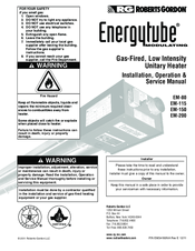
Roberts Gorden Energytube EM-80 Nstallation, Operation And Service Manual (82 pages)
Modulating Gas-Fired, Low Intensity Unitary Heater
Brand:
Roberts Gorden
| Category:
Gas Heater
| Size: 13.88 MB
Table of Contents
Table of Contents
3
SECTION 1: Heater Safety
7
Manpower Requirements
7
Safety Labels and Their Placement
7
Figure 1: Top and Bottom Panel Label Placement
8
Figure 2: Side and Back Panel Label Placement
9
SECTION 2: Installer Responsibility
10
Wall Tag
10
Brooder Wall Tag
10
Corrosive Chemicals
10
National Standards and Applicable Codes
11
SECTION 3: Clearances to Combustibles
12
Required Clearances to Combustibles
12
Figure 3: Standard Reflector
12
Figure 4: One Side Reflector
13
Figure 5: Two Side Reflectors
13
Figure 6: U-Tube, Standard Reflector
13
Figure 7: 2-Foot Deco Grille and Protective Grille
14
Figure 8: Lower Clearance Shield
14
Figure 9: Venting
14
SECTION 4: National Standards and Applicable Codes
15
Gas Codes
15
Aircraft Hangars
15
Public Garages
15
Electrical
15
Venting
15
High Altitude
15
SECTION 5: Major Components
16
Figure 10: Major Component Descriptions
16
Standard Parts List
17
Table 1: Contents of Burner Carton
17
Table 2: Contents of Core and Extension Packages
17
Table 3: EM-Series Component Package Guide
17
SECTION 6: Heater Installation
18
Figure 11: Critical Hanger Placement
19
Figure 12: Linear Heater Assembly Overview
20
Figure 13: Linear Heater Layout Overview
21
Burner Tube Installation
22
Tube Clamp Package Installation
22
Coupling and Tube Assembly
23
Turbulator Installation
24
Reflector Installation
25
Burner Installation
27
SECTION 7: Optional Heater Accessories
28
U-Tube Configuration
28
Figure 14: U-Tube Heater Assembly Overview
29
Figure 15: U-Tube Heater Layout Overview
30
Elbow Package Configuration
31
Figure 16: Reflector Joint Detail
32
Reflector Side Extension
33
Lower Clearance Shield Installation
34
Two-Foot Decorative Grille Installation
34
Protective Grille Installation
36
SECTION 8: Venting
37
Venting
37
Unvented Operation
37
Horizontal Venting
38
Vertical Venting
38
Unvented Operation Tube Termination
38
Length Requirements
38
Horizontal Ventilation 4" (10 CM) Pipe
38
Figure 17: Tube Termination
38
Vertical Ventilation 4" (10 CM) Pipe
39
Common Side Wall Venting
39
Common Vertical Venting
40
Outside Combustion Air Supply
41
SECTION 9: Gas Piping
43
Figure 18: Gas Connection with Flexible Gas Hose
44
SECTION 10: Wiring
45
Heater Wiring for Use with Brooder Controller
45
Figure 19: Line Voltage Power Wiring
45
Figure 20: Low Voltage Brooder Control Wiring
46
Standard Heater Configuration
47
Figure 21: Zone Sensor Wiring Diagram
47
Central and Satellite Heaters (Zoning Capability)
48
Figure 22: Central Heater Jumper Settings
48
Figure 23: Satellite Heater Jumper Setting
49
Communication Wiring Within a Zone of Heaters
50
Figure 24: Communication Wiring Within a Zone of Heaters
50
Communication Wiring Within a Zone of Heaters (Continued)
51
Figure 24: Communication Wiring Within a Zone of Heaters (Continued)
51
Heat Demand Control Wiring
52
Figure 25: Thermostat Control Wiring Diagram
52
Table 4: Cable Requirements
54
Figure 26: Analog Control Signal Wiring Diagram
55
Figure 27: Potentiometer Control Wiring Diagram
56
Figure 28: Modulating Thermostat Wiring Diagram
57
Figure 29: Modulating Thermostat Wiring Diagram (Lonworks [2-10Vdc with 500 Ohm Resistor] Optional)
58
Figure 30: Modulating Thermostat Wiring Diagram with Bacnet (Optional)
59
Internal Wiring
60
Ladder Diagram
61
Electrical Connection to the Burner
61
Low Voltage Control Wiring Installation
62
SECTION 11: Operation and Maintenance
63
Sequence of Operation
63
To Shut off Heater
63
To Start Heater
63
Pre-Season Maintenance and Annual Inspection
63
SECTION 12: Troubleshooting
66
Control LED
67
General LED Codes
67
Troubleshooting Flow Chart
69
Manifold Gas Pressure Measurement
71
Pneumatic Connections
72
SECTION 13: Replacement Parts
73
SECTION 14: General Specifications
76
Material Specifications
76
Heater Specifications
76
Suspension Specifications
76
Controls Specifications
76
SECTION 15: the ROBERTS GORDON
77
MODULATING Warranty
77
Energytube
77
Advertisement
Advertisement
Related Products
Roberts Gorden Energytube EM-150
Roberts Gorden Energytube EM-115
Roberts Gorden Energytube EM-200
Roberts Gorden EP-203
Roberts Gorden EP 200 Series
Roberts Gorden EP 301
Roberts Gordon Econo-Ray ER-80
Roberts Gorden EP-303
Roberts Gorden CoRayVac E-12
Roberts Gorden CoRayVac E-12a
Roberts Gorden Categories
Heater
Heating System
Electric Heater
Gas Heater
Water Pump
More Roberts Gorden Manuals
Login
Sign In
OR
Sign in with Facebook
Sign in with Google
Upload manual
Upload from disk
Upload from URL