Sign In
Upload
Manuals
Brands
Rittal Manuals
Industrial Equipment
3314.250
Rittal 3314.250 Liquid Cooling Package Manuals
Manuals and User Guides for Rittal 3314.250 Liquid Cooling Package. We have
1
Rittal 3314.250 Liquid Cooling Package manual available for free PDF download: Assembly And Operating Instructions Manual
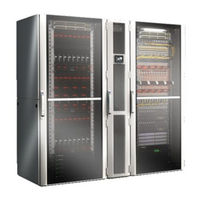
Rittal 3314.250 Assembly And Operating Instructions Manual (136 pages)
Brand:
Rittal
| Category:
Industrial Equipment
| Size: 31 MB
Table of Contents
Table of Contents
3
Notes on Documentation
5
CE Labelling
5
Storing the Documents
5
Symbols in These Operating Instructions
5
Other Applicable Documents
5
Normative Instructions
5
Legal Information Concerning the Operating Instructions
5
Copyright
5
Software Update
5
Safety Instructions
6
General Safety Instructions
6
Safety Instructions for Transportation
6
Safety Instructions for Assembly
6
Safety Instructions for Installation
6
Safety Instructions for Operation
6
Safety Instructions for Maintenance
7
Safety Instructions on Shutting down
7
Operating and Technical Staff
7
Personal Protective Equipment
7
Rohs Compliance
7
Safety Instructions
7
Measures for Products and Systems
7
Device Description
9
General Functional Description
9
Control Modes
10
General Information
10
Automatic Mode
10
Delta-T Mode
11
External Temperature Sensor
11
Ambient Conditions
11
Air Routing
14
General
14
LCP Rack
14
LCP Inline Protruding and LCP Inline Flush
15
Equipment Assembly
16
Schematic Design
16
Unit Components
16
Air/Water Heat Exchanger
17
Fan Module
18
Water Module with Cold Water Connection
18
Proper and Improper Usage
18
Supply Scope of a Liquid Cooling Package
19
Unit-Specific Instructions
19
Creation of Redundancy in the LCP Rack
19
Dewpoint Control
21
Type Code
21
Meaning of the Digits in the Type Code
21
Standard Versions
22
Transportation and Handling
23
Transportation
23
Unpacking
23
Assembly and Siting
26
General
26
Installation Site Requirements
26
Prepare the Room for Installation of the LCP Inline Protruding and LCP Inline Flush
26
Installation Regulations for the LCP Inline Protruding and LCP Inline Flush
27
Assembly Procedure with a VX IT Server Enclosure
28
General
28
Dismantle the Side Panels
28
Seal the Server Enclosure
28
Fit the Rear Adaptor on the LCP Inline
29
Installation and Baying of the Liquid Cooling Package
31
Mounting the Side Panel
33
Punch Outs
34
Fan Installation
34
Removing a Fan Module
34
Installing a Fan Module
35
Install the Optional Display (SK 3311.030)
37
Installing the Optional Condensate Pump (SK 3314.012)
38
Positioning the Pressure Sensors
41
Installation
42
Connecting the Liquid Cooling Package
42
Electrical Connection
42
Potential Equalisation
46
Cooling Water Connection
46
Connecting the Condensate Discharge
49
Bleeding the Air from the Heat Exchanger
50
Cooling Operation and Control Characteristics
50
Configuration
51
General
51
HTTP Connection
51
Making the Connection
51
Changing the Network Settings
51
Changing the Measurement Units
52
LCP Configuration
52
Settings
56
Operation
57
Description of Operating and Display Components
57
Control Unit Hardware for the Liquid Cooling Package
57
Description of Operation
58
General
58
Acknowledging Messages
59
Operation in Stand-Alone Mode
59
Automatic Door Opening, LCP Rack
62
Extended Options by Connecting the Liquid Cooling Package to a Network
64
General Operation
64
Layout of Screen
64
Navigation Area in Left-Hand Section
64
Index Tabs in the Configuration Area
65
Message Display
65
Other Displays
66
Changing Parameter Values
66
Logging off and Changing the Password
67
Reorganising the Connected Components
68
Monitoring Index Tab
68
Device
69
Air Temperature
69
Fans
70
Coolant
70
Valve
71
Cooling Capacity
72
Leakage Sensor
72
Condensate
72
Setup
73
Operating Data
73
Remote
73
Features
74
Configuration Index Tab
77
Door Opening
77
Tasks
78
Updates and Data Backup
80
Troubleshooting
81
General Faults
81
Messages on the Display
83
Inspection and Maintenance
84
Storage and Disposal
85
Technical Specifications
86
Output Class 30 Kw
86
LCP Rack Flush CW and LCP Inline Protruding CW (CW = Chilled Water)
86
LCP Inline Flush CW (CW = Chilled Water)
86
Output Class 35 Kw
87
LCP Inline Flush CWG (CWG = Chilled Water Glycol)
87
Output Class 44 Kw
87
LCP Rack Flush CWG and LCP Inline Protruding CWG (CWG = Chilled Water Glycol)
87
Output Class 53 Kw
88
LCP Rack Flush CW and LCP Inline Protruding CW (CW = Chilled Water)
88
Spare Parts
89
Accessories
90
Further Technical Information
92
Information Concerning the Filling and Additive Water
92
Characteristic Curves
93
Pressure Loss
98
Overview Drawings
100
Circuit Diagram
106
Wiring Diagram
119
Water Circulation Diagram
120
Rittal Liquid Cooling Package
120
Declaration of Conformity
121
The Cooling Medium
122
Glossary
130
Customer Service Addresses
131
Advertisement
Advertisement
Related Products
Rittal 3314.130
Rittal 3314.230
Rittal 3314.260
Rittal 3314.530
Rittal 3314.550
Rittal 3314.560
Rittal 3314.540
Rittal 3314.542
Rittal 3314.570
Rittal 3375.544
Rittal Categories
Industrial Equipment
Enclosure
Accessories
Racks & Stands
Control Unit
More Rittal Manuals
Login
Sign In
OR
Sign in with Facebook
Sign in with Google
Upload manual
Upload from disk
Upload from URL