Sign In
Upload
Manuals
Brands
Rigol Manuals
Power Supply
DP900 Series
Rigol DP900 Series Manuals
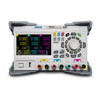
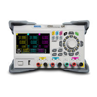
Manuals and User Guides for Rigol DP900 Series. We have
5
Rigol DP900 Series manuals available for free PDF download: Programming Manual, User Manual, Manual, Quick Manual
Rigol DP900 Series Programming Manual (141 pages)
Programmable Linear DC Power Supply
Brand:
Rigol
| Category:
Power Supply
| Size: 2 MB
Table of Contents
Table of Contents
3
Document Overview
9
SCPI Introduction
11
SCPI Status Register
14
Questionable Status Register
16
Table 3.1 Definitions of the Bits in the Questionable Status Register and the
17
Decimal Values Corresponding to Their Binary Weights
17
Table 3.2 Definitions of the Bits in the Channel Questionable Status Register and
18
The Decimal Values Corresponding to Their Binary Weights
18
Table 3.3 Definitions of the Bits in the Channel Questionable Status SUMMARY
18
Register and the Decimal Values Corresponding to Their Binary Weights
18
Standard Event Register
19
Table 3.4 Definitions of the Bits in the Standard Event Register and the Decimal
19
Values Corresponding to Their Binary Weights
19
Status Byte Register
20
Table 3.5 Definitions of the Bits in the Status Byte Register and the Decimal
20
Command System
21
Analyzer Commands
21
Analyzer:common:measure:type
21
Analyzer:current:measure:type
22
Analyzer:current:thre
22
Analyzer:save:route
23
Analyzer:save:state
24
Analyzer:state
25
Analyzer:type
26
Apply Commands
26
Table 4.9 Ranges and Default Values of Voltage/Current Corresponding to each
26
Channel of Different Models of DP900 Series
26
Apply
27
IEEE488.2 Commands
28
Cls
28
Esr
29
Values Corresponding to Their Binary Weights
29
Ese
30
Idn
31
Opc
31
Opt
32
Psc
33
Rcl
34
Rst
35
Sav
35
Sre
36
Stb
37
Trg
38
Tst
38
Wai
39
Instrument Commands
39
Instrument:nselect
39
Instrument[:Select]
40
Instrument[:Select]
41
LIC Commands
41
Lic:set
41
Lic:install
42
Measure Commands
43
Measure[:Scalar]:All[:DC]
44
Measure[:Scalar]:Current[:DC]
44
Measure[:Scalar]:Power[:DC]
45
Measure[:Scalar][:Voltage][:DC]
46
Memory Commands
47
Memory:catalog
47
Memory:cdirectory
48
Memory:delete
48
Memory:disk
49
Memory:load
50
Memory:lock
50
Memory:mdirectory
51
Memory:store
52
Memory:valid
53
Output Commands
53
Table 4.33 Range and Default Value of Overvoltage/Overcurrent Protection
53
Output:CVCC
54
Output:mode
54
Output:ocp:alar
55
Output:ocp:ques
56
Output:ocp:clear
57
Output:ocp:delay
57
Output:ocp[:State]
58
Output:ocp:value
59
Output:ovp:alar
60
Output:ovp:ques
60
Output:ovp:clear
61
Output:ovp[:State]
62
Output:ovp:value
63
Output:pair
64
Output[:State]
64
Output:track[:State]
65
Source Commands
66
Source[<N>]]:Current[:Level][:Immediate][:Amplitude]
66
Source[<N>]]:Current[:Level]
67
[:Immediate]:Step[:Increment]
67
Source[<N>]]:Current:protection:clear
68
Source[<N>]]:Current:protection[:Level]
69
Source[<N>]]:Current:protection:state
70
Source[<N>]]:Current:protection:tripped
71
Source[<N>]]:Voltage[:Level][:Immediate][:Amplitude]
72
Source[<N>]]:Voltage[:Level]
73
[:Immediate]:Step[:Increment]
73
Source[<N>]]:Voltage:protection:clear
74
[:Source[<N>]]:Voltage:protection[:Level]
75
[:Source[<N>]]:Voltage:protection:state
76
[:Source[<N>]]:Voltage:protection:tripped
77
Status Commands
77
Status:operation:condition
78
Status:operation:enable
78
Status:operation[:Event]
79
Status:preset
79
Status:questionable:enable
80
Status:questionable[:Event]
81
Status:questionable:instrument:enable
81
Status:questionable:instrument[:Event]
82
Status:questionable:instrument:isummary[<N>]:Condition
83
Status:questionable:instrument:isummary[<N>]:Enable
84
Status:questionable:instrument:isummary[<N>][:Event]
85
System Commands
86
System:beeper:immediate
86
System:beeper[:State]
86
System:brightness
87
System:communicate:lan
87
System:communicate:lan:apply
88
System:communicate:lan:autoip[:State]
88
System:communicate:lan:dhcp[:State]
89
System:communicate:lan:dns
90
System:communicate:lan:ipaddress
91
System:communicate:lan:gateway
92
System:communicate:lan:mac
92
System:communicate:lan:manualip[:State]
93
System:communicate:lan:smask
94
System:communicate:rlstate
95
System:error[:Next]
96
System:klock:state
96
System:language:type
97
System:local
98
System:poweron
98
System:print
99
System:remote
99
System:rwlock
100
System:saver
101
System:sync[:State]
101
System:tmode
102
System:tlock
103
System:version
104
Timer Commands
104
Timer:cycles
104
Timer:channel
105
Timer:endstate
106
Timer:groups:num
106
Timer:group:index
107
Timer:group:parameter
108
Timer:group:delete
109
Timer:run
110
Timer[:State]
110
Timer:templet:construct
111
Timer:templet:fallrate
112
Timer:templet:interval
112
Timer:templet:invert
113
Timer:templet:maxvalue
114
Timer:templet:minvalue
115
Timer:templet:object
116
Timer:templet:period
117
Timer:templet:points
117
Timer:templet:riserate
118
Timer:templet:select
119
Timer:templet:symmetry
120
Timer:templet:width
120
Timer:templet:stair
121
Timer:trig
122
Trigger Commands
122
Trigger:in[:Enable]
123
Trigger:in:immediate
123
Trigger:in:response
124
Trigger:in:source
125
Trigger:in:type
125
Trigger:out:polarity
126
Trigger:out:source
127
Trigger:out[:Enable]
128
Programming Examples
129
Programming Preparations
129
Labview Programming Example
129
Visual Basic Programming Example
134
Visualc++ Programming Example
136
Advertisement
Rigol DP900 Series User Manual (101 pages)
Programmable linear DC power supply
Brand:
Rigol
| Category:
Power Supply
| Size: 4 MB
Table of Contents
Table of Contents
3
Safety Requirement
9
General Safety Summary
9
Safety Notices and Symbols
11
Measurement Category
11
Ventilation Requirement
12
Working Environment
12
Care and Cleaning
14
Environmental Considerations
14
Product Overview
16
Document Overview
18
Quick Start
20
General Inspection
20
Appearance and Dimensions
21
Front Panel
21
Figure 4.1 Front View
21
Figure 4.2 Side View
21
Figure 4.3 DP900 Front Panel
22
Figure 4.4 DP900 Output Terminals
24
Rear Panel
25
Figure 4.5 DP900 Rear Panel
25
Table 4.1 DP900 Rear Panel Description
25
User Interface
26
Figure 4.6 User Interface
27
Table 4.2 User Interface Description
27
Connecting to Power
28
Table 4.3 AC Input Power Specifications (Including AC Selector Setting)
28
Power-On Inspection
29
Connecting the Outputs
30
Replacing the Fuse
30
Using the Built-In Help System
31
Table 4.4 Fuse Rating
31
Figure 4.7 Help Interface
32
Using the Protection Function
33
Figure 5.1 CH1 Output Settings Interface
33
Constant Voltage Output
35
Constant Current Output
38
Series/Parallel Connections
39
Series Connections
39
Figure 8.1 Series Output Interface
40
Parallel Connections
41
Figure 8.2 External Series Circuit
41
Figure 8.3 Parallel Output Interface
42
Figure 8.4 External Parallel Circuit
43
Arb Function
44
Figure 9.1 Arb Main Interface
44
Setting Arb Properties
45
Figure 9.2 Arb Settings Interface
45
Arb Editor
47
Figure 9.3 Arb Editor Interface
47
Inserting a Single Point
48
Editing Waveform Templates
48
Figure 9.4 Template Editing Menu
48
Table 9.1 Arb Parameters (Template)
52
Delete
54
Import and Export
54
Enabling the Arb Output
55
Figure 9.5 Arb Output Interface
55
Analyzer
56
Common Analysis
56
Figure 10.1 Analyzer Main Interface
56
Selecting Analysis Object
57
Figure 10.2 Common Analysis Setting Interface
57
Figure 10.3 Analysis Object Setting Menu
57
Selecting Statistical Method
58
Pulse Current Analysis
59
Figure 10.4 Pulse Current Analysis Setting Interface
59
Data Logging
60
Figure 10.5 Pulse Current Analysis Interface
60
Figure 10.6 Log Setting Interface
60
Print Screen
61
Label Control
61
Trigger
62
Figure 11.1 Digital Port Connections
62
Trigger Input
63
Figure 11.2 Trigger Setting Interface
63
Figure 11.3 Trigger Input Setting Interface
64
Trigger Output
65
Figure 11.4 Trigger Output Setting Interface
65
Store and Recall
67
Figure 12.1 Disk Interface
67
Select
68
Save
68
Read
69
Delete
69
Copy and Paste
70
Utility
71
System Settings
71
Instrument Settings
71
Figure 13.1 Utility Interface
71
Figure 13.2 Instrument Settings Interface
72
Table 13.1 Factory Default Values
72
Display Options
74
Output Settings
75
Figure 13.3 Display Options Interface
75
Track Mode
76
Safe Mode
76
Figure 13.4 Output Settings Interface
76
Output Connection
77
Output off Mode
77
Interface Settings
78
LXI Status
78
Figure 13.5 Interface Settings
78
Figure 13.6 LXI Status Interface
79
LXI Setting
80
Figure 13.7 LXI Settings Menu
80
USB Configuration
82
Option Settings
83
Figure 13.8 USB Configuration Interface
83
Figure 13.9 Option Settings Interface
84
Locking/Unlocking the Front Panel
86
Remote Control
88
Remote Control Via USB
88
Remote Control Via LAN
89
Troubleshooting
91
Specifications
93
Appendix
99
Appendix A: Accessories and Options
99
Appendix B: Warranty
100
Rigol DP900 Series User Manual (101 pages)
Brand:
Rigol
| Category:
Power Supply
| Size: 2 MB
Table of Contents
Table of Contents
3
Safety Requirement
9
General Safety Summary
9
Safety Notices and Symbols
11
Measurement Category
11
Ventilation Requirement
12
Working Environment
12
Care and Cleaning
14
Environmental Considerations
14
Product Overview
16
Document Overview
18
Quick Start
20
General Inspection
20
Appearance and Dimensions
21
Front Panel
21
Figure 4.1 Front View
21
Figure 4.2 Side View
21
Figure 4.3 DP900 Front Panel
22
Figure 4.4 DP900 Output Terminals
24
Rear Panel
25
Figure 4.5 DP900 Rear Panel
25
Table 4.1 DP900 Rear Panel Description
25
User Interface
26
Figure 4.6 User Interface
27
Table 4.2 User Interface Description
27
Connecting to Power
28
Table 4.3 AC Input Power Specifications (Including AC Selector Setting)
28
Power-On Inspection
29
Connecting the Outputs
30
Replacing the Fuse
30
Using the Built-In Help System
31
Table 4.4 Fuse Rating
31
Figure 4.7 Help Interface
32
Using the Protection Function
33
Figure 5.1 CH1 Output Settings Interface
33
Constant Voltage Output
35
Constant Current Output
38
Series/Parallel Connections
39
Series Connections
39
Figure 8.1 Series Output Interface
40
Parallel Connections
41
Figure 8.2 External Series Circuit
41
Figure 8.3 Parallel Output Interface
42
Figure 8.4 External Parallel Circuit
43
Arb Function
44
Figure 9.1 Arb Main Interface
44
Setting Arb Properties
45
Figure 9.2 Arb Settings Interface
45
Arb Editor
47
Figure 9.3 Arb Editor Interface
47
Inserting a Single Point
48
Editing Waveform Templates
48
Figure 9.4 Template Editing Menu
48
Table 9.1 Arb Parameters (Template)
52
Delete
54
Import and Export
54
Enabling the Arb Output
55
Figure 9.5 Arb Output Interface
55
Analyzer
56
Common Analysis
56
Figure 10.1 Analyzer Main Interface
56
Selecting Analysis Object
57
Figure 10.2 Common Analysis Setting Interface
57
Figure 10.3 Analysis Object Setting Menu
57
Selecting Statistical Method
58
Pulse Current Analysis
59
Figure 10.4 Pulse Current Analysis Setting Interface
59
Data Logging
60
Figure 10.5 Pulse Current Analysis Interface
60
Figure 10.6 Log Setting Interface
60
Print Screen
61
Label Control
61
Trigger
62
Figure 11.1 Digital Port Connections
62
Trigger Input
63
Figure 11.2 Trigger Setting Interface
63
Figure 11.3 Trigger Input Setting Interface
64
Trigger Output
65
Figure 11.4 Trigger Output Setting Interface
65
Store and Recall
67
Figure 12.1 Disk Interface
67
Select
68
Save
68
Read
69
Delete
69
Copy and Paste
70
Utility
71
System Settings
71
Instrument Settings
71
Figure 13.1 Utility Interface
71
Figure 13.2 Instrument Settings Interface
72
Table 13.1 Factory Default Values
72
Display Options
74
Output Settings
75
Figure 13.3 Display Options Interface
75
Track Mode
76
Safe Mode
76
Figure 13.4 Output Settings Interface
76
Output Connection
77
Output off Mode
77
Interface Settings
78
LXI Status
78
Figure 13.5 Interface Settings
78
Figure 13.6 LXI Status Interface
79
LXI Setting
80
Figure 13.7 LXI Settings Menu
80
USB Configuration
82
Option Settings
83
Figure 13.8 USB Configuration Interface
83
Figure 13.9 Option Settings Interface
84
Locking/Unlocking the Front Panel
86
Remote Control
88
Remote Control Via USB
88
Remote Control Via LAN
89
Troubleshooting
91
Specifications
93
Appendix
99
Appendix A: Accessories and Options
99
Appendix B: Warranty
100
Advertisement
Rigol DP900 Series Manual (58 pages)
Brand:
Rigol
| Category:
Power Supply
| Size: 2 MB
Table of Contents
Table of Contents
3
Safety Requirement
5
General Safety Summary
5
Safety Notices and Symbols
7
Document Overview
8
Overview
9
Test Preparations
9
Voltage and Current Values
10
Recommended Test Equipment
10
Recommended Model
11
Specification
11
Test Precautions
11
Test Result Record
12
Constant Voltage (CV) Tests
13
Preparations
13
CV Load Regulation Rate (CV Load Effect)
13
CV Linear Regulation Rate (CV Source Effect)
15
CV Ripple and Noise
18
Transient Response Time
22
CV Programming and Readback Accuracy
24
Constant Current (CC) Tests
29
Preparations
29
CC Load Regulation Rate (CC Load Effect)
29
CC Linear Regulation Rate (CC Source Effect)
31
CC Programming and Readback Accuracy
34
Appendix
38
Appendix A: Test Record Form
38
DP932A Performance Verification Test Record Form
38
DP932U Performance Verification Test Record Form
43
DP932E Performance Verification Test Record Form
47
Specifications
52
Rigol DP900 Series Quick Manual (29 pages)
Programmable linear DC power supply
Brand:
Rigol
| Category:
Power Supply
| Size: 2 MB
Table of Contents
Safety Requirement
3
General Safety Summary
3
Safety Notices and Symbols
3
Measurement Category
4
Ventilation Requirement
5
Working Environment
5
Care and Cleaning
6
Environmental Considerations
7
Document Overview
8
General Inspection
9
Production Introduction
10
Appearance and Dimensions
10
Front Panel
11
User Interface
15
To Prepare for Use
18
Connecting to Power
18
Power-On Inspection
19
Connecting the Outputs
19
Replacing the Fuse
20
Using the Built-In Help System
22
Troubleshooting
24
Remote Control
26
Advertisement
Related Products
Rigol DP932A
Rigol DP932U
Rigol DP932
Rigol DP932E
Rigol DP700 Series
Rigol DP821
Rigol DP831A
Rigol DP811A
Rigol DP822A
Rigol DP813
Rigol Categories
Test Equipment
Measuring Instruments
Portable Generator
Power Supply
Multimeter
More Rigol Manuals
Login
Sign In
OR
Sign in with Facebook
Sign in with Google
Upload manual
Upload from disk
Upload from URL