Sign In
Upload
Manuals
Brands
Rievtech Manuals
Control Unit
EXM-12DC-DA-RT-WIFI
Rievtech EXM-12DC-DA-RT-WIFI Manuals
Manuals and User Guides for Rievtech EXM-12DC-DA-RT-WIFI. We have
2
Rievtech EXM-12DC-DA-RT-WIFI manuals available for free PDF download: User Manual
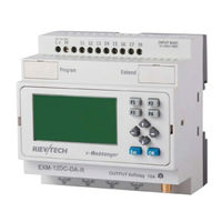
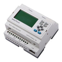
Rievtech EXM-12DC-DA-RT-WIFI User Manual (443 pages)
Applied to EXM series CPU& Extensions.
Brand:
Rievtech
| Category:
Control Unit
| Size: 12 MB
Table of Contents
Table of Contents
7
Contents
7
Chapter 1 General Introduction to X-Messenger
12
Overview
12
Highlight Feature
13
Chapter 2 Applications
14
Application Overview
14
Application Architecture
14
Chapter 3 Hardware Models and Resources
18
Naming Rules of EXM Series
18
Hardware Model Selection
18
Resources
20
GSM /GPRS Module Built- in
20
How to Establish the Connection between X-Messenger and PC Via GPRS
21
E-Mail and How to Set
26
How to Change the Register Value(F,Q,AQ,AF,REG) or Phonebook Via SMS
28
How to Modify the PIN Via SMS
39
How to Modify the GPRS Parameters and Email Parameters Via SMS
40
How to Modify the Email Address of the Receiver Via SMS
45
Voice Alarm
47
Ethernet Module with Built-In Webserver
61
How to Separate the New Version and Old Version
61
How to Configure the Network Parameters through Program Software
62
How to View and Configure the Ethernet Parameters through LCD Panel
67
How to Create the Communication between the CPU and PC through Ethernet
71
How to Log on the Built-In Web Server
82
How to Establish the Communication between New Ethernet Cpus
94
How to Configure the Ethernet Modem(Old Series)
122
SD Card Data Logging
149
Communication Interface
150
6Multiple Modbus Communication Protocol
151
LCD Panel Instruction
154
Antenna
157
Structure & Dimension
157
Chapter 4 Installing/Removing EXM
159
DIN Rail Mounting
159
Wall-Mounting
161
Wiring EXM
162
Connecting the Power Supply
162
Connecting X-Messenger Inputs
163
Connecting EXM Outputs
165
Chapter 5 Configuring & Software-Standard Mode
167
System Requirements
167
General
168
Create Connection
169
Edit Telephone Book
169
Standard Mode Settings
169
Device Types
170
Automatic Provider Search
170
Manual Provider Search
170
Status Messages
171
Input Configuration
171
General
171
Digital Inputs
172
Parallel Message Handling
172
Time Delayed Message for Input on
173
Time Delayed Message for Output off
174
Analogue Inputs
174
Scaling and Units
174
Message Delay
178
Message Block
178
Output Configuration
179
General
179
Timer Function
179
CALL-IN Function
180
I/O Status Remote Request
180
Digital Inputs
181
Analogue Inputs
181
Outputs
181
Chapter 6 Configuring & Software-Customized Mode
182
X-Messenger Functions
183
General Input & Output Functions
183
Inputs
183
Cursor Keys
184
Outputs
184
Permanent Logical Levels HI and lo
184
Open Connector
185
Panel Key
185
Shift Register Bits
186
Analog Inputs
186
F (Digital Flag)
187
AF (Analog Flag)
187
SMS Message Input
188
SMS Message Output
190
Sms Message Input Output
195
GPRS Connect
199
GPRS Data Upload
201
Basic Functions List - GF
207
And
208
AND with Edge Evaluation
209
Nand
210
NAND with Edge Evaluation
211
Nor
213
Xor
214
Not
214
Basics on Special Functions
215
Designation of the Inputs
215
Time Response
216
Backup of the Real-Time Clock
217
Retentivity
217
Parameter Protection
217
Calculating the Gain and Offset of Analog Values
217
Special Functions List - SF
220
On-Delay
222
Off-Delay
224
On-/Off-Delay
225
Retentive On-Delay
227
Wiping Relay (Pulse Output)
228
Edge Triggered Wiping Relay
229
Asynchronous Pulse Generator
231
Random Generator
232
Stairway Lighting Switch
234
Multiple Function Switch
235
Weekly Timer
237
Yearly Timer
240
Up/Down Counter
246
Hours Counter
248
Threshold Trigger
251
Latching Relay
252
Pulse Relay
254
Message Text
255
How to Change Parameters of Blocks in Displayed Message
262
Softkey
264
Shift Register
265
Analog Comparator
267
Analog Threshold Trigger
270
Analog Amplifier
273
Analog Differential Trigger
276
Analog Multiplexer
278
System Cover
280
Pulse Width Modulator (PWM)
281
Analog Ramp
285
Analog Math
287
Analog Math Error Detection
289
Modbus Read
291
Modbus Write
298
Modbus Read Write
302
Data Latching Relay
309
PI Controller
311
Memory Write
323
Memory Read
329
Word to Bit
333
Bit to Word
335
Device Reset
338
Comport Status
339
Analog Filter
343
Max/Min
344
Average Value
348
Astronomical Clock
349
Stopwatch
351
Cam Control
353
Angular Cam Timer
354
Pumps Management
355
Defrost
357
Comparison of 2 Values
359
Multicompare
360
Compare in Zone
361
Conversion Word Bits
362
Conversion Bits Word
363
Demultiplexer
363
Multiplexing
364
Multiplexer
365
Square Boot
366
Sin Cos
366
Enter into "Customized Mode
367
Main Functions
369
Operation Instructions of Customized Mode
370
Menu Bar
370
File
370
Edit
371
Tools
371
Sms
372
View
374
Help
374
Toolbar
375
Programming Toolbar
376
Simulation Tool and Status Window
377
Basic Operation
380
Open File
380
Open New File
380
Open Existed Document
381
Edit Function Diagram Program
382
Place Function Block
382
Edit Property of Function Block
383
Setup Link
384
Delete Function Block or Delete Link
386
Simulation Running
386
Save and Print
388
Modify Password and Transfer the Program
389
How to Prevent Your Program from Being Copied/Stolen
391
On-Line Monitoring/Test Circuit Program
393
Chapter 7 Description of the WIFI Module Built-In the EXM WIFI CPU
399
Functional Description
400
Operation Guideline
405
10/100M Ethernet Interface
414
HF-A11 Ethernet Interface Networking (as AP)
415
How to Configure the Wifi Module by the Esmsconfig.exe
417
How to Configure WIFI Connection (TCP Protocol) Among EXM WIFI Cpus
426
Appendix
437
A Technical Data
437
Advertisement
Rievtech EXM-12DC-DA-RT-WIFI User Manual (355 pages)
Micro PLC Programmable Relay
Brand:
Rievtech
| Category:
Relays
| Size: 20 MB
Table of Contents
Table of Contents
5
Products Covered
15
Product Safety
15
Qualified Personnel
15
Trademarks
15
Copyright Rievtech 2015 All Rights Reserved
15
Disclaim of Liability
15
Additional Support
16
Overview
17
Feature Highlights
17
Some of the Things Xlogic Can Do for You
17
Xlogic Devices
18
Communication / Network
18
ELC and PR-Series CPU Naming Convention
21
ELC, EXM and PR-Series Expansion Unit Naming Convention
23
Range of Hardware
24
Non-Expandable CPU Range
24
Expandable CPU Range
24
Expansion Modules
28
Accessories
28
Structure & Dimensions
29
Series CPU and EXM-E Expansion Modules
29
PR-12 Series with LCD
29
PR-12 Series Without LCD
29
PR-14 and PR-18 Series
29
PR-24 Series
30
PR-E Expansion Modules
30
EXM GSM/GPRS Built-In Module
31
How to Establish Connection between CPU and PC Using GPRS
31
Configuration of E-Mail Settings
38
Changing CPU Information Via SMS
39
Dimensions
45
DIN Rail Mounting
45
Mounting Your Hardware
45
Removing Your Hardware
45
Wall Mounting
46
Drilling Templates for Wall Mounting
46
Wiring
47
Connecting Power
47
Connecting Input Signals
48
DC Type Digital Input Connections
49
AC Type Digital Input Connections
49
Analogue Input Connections (0 to 10 VDC)
49
Analogue Input Connections (0 to 20 Ma)
49
Analogue Input Connections (PT100)
50
Connecting Output Signals
50
Communication Port Instructions
51
Overview of CPU Menu Structure
54
Parameter Assignment Mode
54
LCD Panel Instructions
54
Selecting a Function Page
57
Function
57
How to Switch between RUN and STOP
57
Set Parameter
58
Set Password
61
How to Set the Address of a CPU and Expansion Modules
63
Setting LCD Backlight and Contrast
65
Set Communication Parameters
66
Setting System Date and Time
67
Xlogicsoft Functions
69
General Input and Output Functions
70
Advertisement
Related Products
Rievtech EXM-12DC-DA-R-N-HMI
Rievtech EXM-12DC-DAI-R-HMI
Rievtech EXM-12DC-DA-R-HMI
Rievtech EXM-12DC-DA-R-VN-HMI
Rievtech EXM-12DC-DA-RT-GWIFI
Rievtech EXM-8AC-R-HMI
Rievtech EXM-8DC-PT100-R-HMI
Rievtech EXM-12DC-DA-R
Rievtech EXM-12DC-DA-R-N
Rievtech EXM-12DC-DAI-R
Rievtech Categories
Relays
Control Unit
More Rievtech Manuals
Login
Sign In
OR
Sign in with Facebook
Sign in with Google
Upload manual
Upload from disk
Upload from URL