
Related Manuals for Rievtech x-Messenger Series

Summary of Contents for Rievtech x-Messenger Series
- Page 1 U p d a t e d : F e b r u a r y 22 , 2 0 10 x-Messenger User’s Manual Applied to EXM series CPU& Extensions. Rievtech Electronic Co., Ltd Version:V 1.5...
- Page 2 Contents Introduction Getting started Applications x-Messenger functions Installation and wiring Configuring &software Technical data ...
- Page 3 Introduction Congratulations with your x-Messenger SMS/GSM/GPRS Micro-PLC provided by Rievtech Electronic Co., Ltd. The x-Messenger is a compact and expandable telemetry module combining industrial grade GSM/GPRS modem, PLC controller, data logger, Ethernet module, and multiple communication capability (1RS232&1RS485 ,MODUS ASCII/RTU/TCP, Mater/Slave).
- Page 4 The manual applies to devices of EXM series modules. For more information about expansion module or accessories, please refer to the correlative model instruction files. Safety Guideline This manual contains notices you have to observe in order to ensure your personal safety, as well as to prevent damage to property.
- Page 5 Copyright rievtech 2015 all rights reserved The distribution and duplication of this document or the utilization and transmission of its contents are not permitted without express written permission.
- Page 6 Please consult our website at www.rievtech.com for your closest point of contact or email us at sales@xlogic-relay.com...
-
Page 7: Table Of Contents
Contents Contents ........................................7 Chapter 1 General Introduction to x-Messenger ........................12 1.1 Overview ......................................12 1.2 Highlight feature ..................................13 Chapter 2 Applications ................................14 2.1 Application overview ................................. 14 2.2 Application architecture ................................14 Chapter 3 Hardware models and resources ..........................18 3.1 Naming Rules of EXM Series .............................. - Page 8 4.3 wiring EXM ....................................162 4.3.1 Connecting the power supply ..........................162 4.3.2 Connecting x-Messenger inputs ..........................163 4.3.3 Connecting EXM Outputs ............................165 Chapter 5 Configuring & Software-standard mode ......................167 5.1 System requirements ................................167 5.2 General ......................................168 5.3 Create connection ..................................
- Page 9 6.2.7 Shift register bits ................................. 186 6.2.8 Analog inputs ................................. 186 6.2.9 F (digital flag) ................................187 6.2.10 AF (Analog flag) ................................. 187 6.2.11 SMS message input ..............................188 6.2.12 SMS message output ............................... 190 6.2.13 Sms message Input Output ..........................195 6.2.14 GPRS Connect ................................
- Page 10 6.5.16 Latching relay ................................252 6.5.17 Pulse relay ..................................254 6.5.18 Message text ................................255 6.5.18.1 How to change parameters of blocks in displayed message ? ............ 262 6.5.19 Softkey ..................................264 6.5.20 Shift register ................................265 6.5.21 Analog comparator ..............................267 6.5.22 Analog threshold trigger ............................
- Page 11 6.5.57 Demultiplexer ................................363 6.5.58 Multiplexing ................................. 364 6.5.59 Multiplexer ................................... 365 6.5.60 Square Boot ................................. 366 6.5.61 Sin Cos ..................................366 6.6 Enter into “Customized mode” ............................367 6.7 Main Functions ..................................369 6.8 Operation Instructions of Customized Mode ......................... 370 6.8.1 Menu Bar ..................................
-
Page 12: Chapter 1 General Introduction To X-Messenger
Chapter 1 General Introduction to x-Messenger 1.1 Overview Rievtech x-Messenger SMS/GSM/GPRS Micro-PLC with built-in GSM modem is a device dedicated for remote monitoring, diagnostics and control of objects via short text messages (SMS) , E-mail or CLIP calls. Configurable messages sent from the device with static (text) or dynamic (text and measured values) content are a convenient way of passing important information to the monitoring center, or directly to the defined phone numbers. -
Page 13: Highlight Feature
1.2 Highlight feature Support Quad-band 850/900/1800/1900 MHz frequency Change the bit flag status and register value in the program via SMS Max. 64 different short messages and voice alarms Max. 70 Unicode Characters in one short message Time-based and event-based SMS, Call-IN, Call-Out, Ring. -
Page 14: Chapter 2 Applications
Data logging (ELC-MEMORY is required) Chapter 2 Applications 2.1 Application overview Heating control Pump control Irrigation installations Alarm transmission Level monitoring Temperature monitoring Pressure monitoring Valve control Voltage monitoring Building Automation Factory Automation Machine Automation Remote Maintenance Remote diagnosis Testing Equipment HVAC &... - Page 15 Application 2: Home Security Application 3: Remote monitoring of product level in a tank...
- Page 16 Application 4: Water Pressure Gauge, Fluid Gauge Data Centre, Power substation, Machinery plant unattended, Sites with expensive Application 5: equipment Freezer Warehouse, Walk-in Cold Room, Medical Storage, Data Centre, Power substation, Application 6:...
- Page 17 Laboratory Application 7 Vending/Gaming Machine Monitoring & Reporting System Application 8 Bridge Alarm System Application 9 Farmland Sprinkler System...
-
Page 18: Chapter 3 Hardware Models And Resources
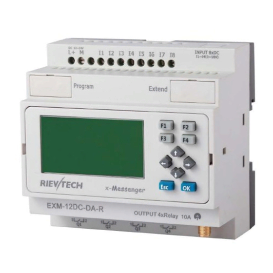
Chapter 3 Hardware models and resources 3.1 Naming Rules of EXM Series EXM : series name 1. Points of total IOs 2. Power Supply ( DC 12~24V, AC 110~240V ) 3. Digital/Analog( D :digital,DA : digital &analog configurable, DAI: digital,(0…10V)&(0/4…20mA)) 4. - Page 19 Model EXM-8AC-R-HMI EXM-12DC-DA-R-HMI EXM-12DC-DA-R-N-HMI Supply Voltage 110~240VAC DC 12-24V DC 12-24V Inputs 6 digital 4 digital/analog+4 digital 4 digital/analog+4 digital Analog Input signal 4 DC (0..10V) 4 DC (0..10V) Outputs 2 relay(10A) 4 relay(10A) 4 relay(10A) High Speed Count(I7,I8) (I7,I8)60kHz (I7,I8)60kHz Yes (64 different short message configuration) GPRS...
-
Page 20: Resources
Note: A. RS485 port can be used as either expansion or communication port, while serving as communication port, EXM-E-RS485 communication module would be required as such port is not photo electricity-isolated. Model EXM-12DC-DA-RT-WIFI EXM-12DC-DA-RT-GWIFI Supply Voltage DC 12-24V DC 12-24V Inputs 4 digital/analog+4 digital Analog Input signal... -
Page 21: How To Establish The Connection Between X-Messenger And Pc Via Gprs
3.3.1.1 How to establish the connection between x-Messenger and PC via GPRS? A. Here under is GPRS network connection’s sketch map: x-Messenger CPU(EXM) shall work as client at Internet and PC shall act as SERVER . Meanwhile, Internet service provider would automatically assign one dynamic IP address to SIM card inserted into the x-Messenger CPU(EXM). - Page 22 2. LAN Address Disposal User shall assign x-Messenger CPU’s communication port for GPRS to IP address of server PC. e.g. “5002” is just x-Messenger CPU’s communication port for GPRS, and “5001” had been assigned to computer 1 as well, further let’s suppose 192.168.0.119 is just IP address for server PC(computer1, in above sketch map), then Port “5002”...
- Page 23 take a look at below demonstration configure as example for your better understanding. C. Hereunder is a demonstration example illustrating GPRS connection establishment between remote x-Messenger and eSmsConfig installed in the server PC(or other server software). Step1: A static IP address shall be required, for example, it is 221.226.189.74, and you can refer to the forementioned A&B for the detailed explanation on static IP address.
- Page 24 Fig 3 You can set the IP address and the port number in the above dialog box. (It is based on your server(fixed IP address). Step6: Click the “ ” button. After set successfully, you can establish the connection via GPRS between x-Messenger and eSmsConfig (your server).
- Page 25 the device name and the IP address will displayed. Step8: After the connection is established successfully, Program download/upload and data remote monitoring can be realized in a wireless way all over the world. Application: 1.x-Messenger is client with a dynamic IP address,(SIM card) 2.Server software ( With a static IP address) Option A: The server software can ask for some information such as temperature(analog inputs), level (digital inputs)
-
Page 26: E-Mail And How To Set
3.3.1.2 E-mail and how to set? This chapter is only available under the customized programming mode! Step A: Enable the GPRS function via the menu SMS->Set GPRS param.(The communication port must be opened, and then this step would be available.) Configure the APN(Access Point Name) based on your SIM card and then click "Write"... - Page 27 Click "Write" button to download the parameters into x-Messenger The receiver email address and the alarm text can be edited in the "sms message output" function block.
-
Page 28: How To Change The Register Value(F,Q,Aq,Af,Reg) Or Phonebook Via Sms
1. Set the email address of the receivers, there are 3 receiver E-mail addresses can be set. 2. E-mail caption configuration box. 3. Email contents can be text message and parameters message Text message can be edit in the message editor( 4 in the above figure) Parameters message including such as IO status, analog IO values, kinds of parameters(counters, timers, RTC etc). - Page 29 AF1=2; AQ02=100; Q01=1;Q12=0; F1=1;F2=0; AM1=10; REG1=100; REG100=300; TEL,B002,1,B002,2,B003,1,B003,5:13851448223; RTC=89-01-09,01:32:09,0; Message Parameters: ##** Start characters: (These 4 characters must be included at the start of your message) End character: (This symbol must be used to terminate each line of your message ) Parameters: AF1= 2;...
- Page 30 If you send the short message contents as the ##** TEL,B002,1,B002,2,B003,1,B003,5:13851428396; ,consequently, the receiver1 & receiver2 of the B002 function block and receiver1 & receiver5 of B003 shall turn to 13851428396. (Note: This command is only for 2G version unit, it is unavailable for 4G version unit)
- Page 31 How to modify the all the receiver number of sms message output blocks in the program ? If you want to modify the receiver number in all the sms message output block, you can edit the short message format like this: ##** ALL:TELQ,1:13851448223;...
- Page 32 (Note: This command is only for 2G version unit, it is unavailable for 4G version unit) MsgI01: MsgI02:...
- Page 33 MsgI03: How to modify the all the receiver number of sms message input blocks in the program ? If you want to modify the receiver number in all the sms message input block, you can edit the short message format like this: ##** ALL:TELI,1:13851448223;...
- Page 34 RTC=89-01-09,01:32:09,0; This is used to change the Real time clock of x-Messenger, Year-month-day,hour:minute:second,week; 0: Sunday 1: Monday….. Note: The parameters can include one or more items as above shows, for example, you want to modify the phone number, you only need to edit message as follows: ##** Msg,I01,1,I01,2,I01,3,I01,4,I01,5,I02,1,I02,5,I03,2,I03,4,I03,5:10987654321;...
- Page 35 How to change the phone book(include phone number and Email address)?(Only for 4G version)
- Page 36 When you download program, the xlogic will ask you if wish download the phonebook with program, you need select yes, if the phone book is already changed!
- Page 37 Then we can edit below SMS contents to change the phonebook user1 phone number to “123456789”. ##**PB,cnf,1234∶123456789; ##** Start characters; it means phonebook(includes the phone number and email address) the user name you used(if you use andy in the phone number, here you need edit with andy) 1234 this is password when you want to change the phone number(if you did not set it in the phone book, here you can keep it blank or any other characters).
-
Page 39: How To Modify The Pin Via Sms
3.3.1.4 How to modify the PIN via SMS Note: 1.The PIN code of SIM card must be set on cell-phone, here PIN is only for the x-Messenger. 2.Only when the PIN you set into x-Messenger is the same as the one of SIM CARD, and then the SIM CARD would be in service in normal. -
Page 40: How To Modify The Gprs Parameters And Email Parameters Via Sms
Send an SMS message formatted like the example below ##** PIN:1234; Message Parameters: ##** Start characters: (These 4 characters must be included at the start of your message) End character: (This symbol must be used to terminate each line of your message ) Parameters: PIN:1234;... - Page 41 Send an SMS message formatted like the example below ##** PGPRS: TIMEOUT"60", IPORDOMAIN"0", POWCONNECT"0", APN"CMNET", TADR"221.226.189.74", TPORT"5005", SNUMB"12345678", DOMAIN"www.wyl.com"; Message Parameters: Start characters: ##** (These 4 characters must be included at the start of your message) Parameters interval characters: (This symbol must be used to differentiate each parameter of your message ) End character: (This symbol must be used to terminate each line of your message )
- Page 42 IPORDOMAIN"0", This is to change network mode. IPORDOMAIN"0", means IP address option shall be ticked: And if IPORDOMAIN"1", means Domain Name option shall be ticked. POWCONNECT"0", This command is used to change the option “Connect to ethernet when power on”, POWCONNECT"0", if the contents is this option shall be un-ticked:...
- Page 43 SNUMB"12345678", This command is used to modify the Device Name(serial number) 8 characters in maximum. DOMAIN"www.wyl.com"; This command is used to modify the Domain name. 2.Email parameters and modifications via SMS. Email parameters can be viewed from menu “SMS-> Set email params” Send an SMS message formatted like the example below ##** PEMAIL:...
- Page 44 SMTPPORT"25", SMTPUSER"xLogic@163.com", SMTPPWD"12345678", SENDNAME"chen", SENDEMAIL"xLogic@163.com"; Message Parameters: ##** Start characters: (These 4 characters must be included at the start of your message) Parameters interval characters: (This symbol must be used to differentiate each parameter of your message ) End character: (This symbol must be used to terminate each line of your message ) Parameters: PEMAIL :...
-
Page 45: How To Modify The Email Address Of The Receiver Via Sms
##** RPGPRS; RPEMAIL; Parameters RPGPRS; This command is used to check the settings of GPRS. GPRS information would be sent to the user who want to check. RPEMAIL; This command is used to check the settings of GPRS. GPRS information would be sent to the user who want to check. - Page 46 B003(Sms Message Output): How to modify the all the receiver E-mail address of sms message output blocks in the program ? If you want to modify the receiver E-mail address in all the sms message input block, you can edit the short message format like this: ##** ALL:EMALQ,1:xLogic@163.com;...
-
Page 47: Voice Alarm
This is to change receiver 1 for all the sms message output block in the program. EMALQ, means the the receiver email address in the sms message output block. means the receiver 1 in the block, this number can be 1 to 3. xLogic@163.com;... - Page 48 Step A. Establish the connection between x-Messenger programming port and the COM port of your PC(RS232/USB) with the download cable(ELC-USB,ELC-RS232, EXM-USB-B ) and the connection between the audio input interface of x-Messenger and the audio output interface of your PC with audio wire(see below figure). Free audio wire accessory, to connect the voice audio input and PC audio output.
- Page 49 Step C. Download voice section. Click menu Tool-> Record Click "Hardware Detect" button.
- Page 50 1. Sound format selection: There are 3 options : 4m ,6m and 8m. In total length range of the recording, the recording of the voice module can be divided into 0-99 sections . (Note: Option1: 4 minutes, the voice sampling frequency is 3.4 K Hz, Option2: 6 minutes, sampling frequency is 2.3 KH z, 8 minutes sampling frequency is 1.7KHz, if you want better sound quality, use a higher sampling frequency.
- Page 51 Relative voice function block description Sound play Description of function The relative voice message would be played if this block were enabled. There are 3 optional ways for sound playing:A. built-in speaker B. External speaker C. Phone alarm voice Connection Description Input En You enable/disable the sound play with the signal at input En.
- Page 52 B.External Speaker External acoustics Sound message : Voice section selection. Sound message: 0 means the voice section 0 from the record manage dialog box.
- Page 53 Voice alarming via phone In your program, you must use the "sms message output'' function block(Refer to the relative chapter in the user manual). Select the "Sms Dial" option, you can choose the receiver phone number from the Phone book. If this block were enabled, x-Messenger would dial to the corresponding user's cell phone.
- Page 54 Telephone key Description of function There are 9 bit flags based on the 1--9 key of the telephone. After you enter into the telephone control mode, and enter # 0, the P0 block would give off one trigger. If you enter # 8, the P8 would give one trigger Operation Instructions of the Voice function for x-Messenger 1.The first five sections (section 0, section 1, section 2, section 3, section 4) are for the voice system.
- Page 55 Section 3: the voice prompt for the wrong password. It will be broadcasted when the wrong password is used. Normal broadcasting can be carried out with this section. Section 4: the voice prompt for dialing to an external telephone. It will be broadcasted when x-Messenger dials an external telephone.
- Page 56 connection set point time, the x-Messenger voice system will stop dialing and cease to broadcast the voice message. The x-Messenger will then redial automatically according to the settings in the "Sms message output block. 2. User must enter a # before entering the password. The broadcasting will then stop and the user should enter a four-digit password within 10 seconds.
- Page 57 Examples of Voice Module Preparations: 1.Connect the x-Messenger to your PC as detailed above. 2.Record message. (The first five messages must be recorded and the other four messages recorded according to the user's needs.) Message 0: Press key #0 and listen to the message. Message 1: Please enter the password.
- Page 58 When programming, requirements are as follows: ① Correct password. ② Set related function block. Program is as follows: MsgI01 "sms message input' function block property box settings: x-Messenger can only answer a call from user1,user2,user3,user4 phone number, other users calls cannot be answered.
- Page 59 Actual Demonstration: ① Dial the telephone No. 1234567 of the voice module from user1--4.. ② It will play Message 1 “Please enter the password.” ③ Enter the preset password via the telephone keys. A. Correct password. It will play Message 2 “Correct password.” If I1 is not triggered, it will play Message 4 “Run normally.
- Page 60 B002 "sms message output' function block settings: Actual Demonstration: ① x-Messenger system detects that the door is not closed. (I1 connected to the switch testing the door status.) I1 is triggered and B002 is activated by I1. Then the x-Messenger will dial user1 11111111 the preset telephone of B002.
-
Page 61: Ethernet Module With Built-In Webserver
There are 2 different Ethernet configuration method for old and new series Ethernet CPU. For the new one, you can refer to chapter 3.3.1--3.3.6. For the old one, please refer to chapter 3.3.7 3.3.1 How to separate the new version and old version? New functions for Ethernet PLC from Rievtech is released. Included CPU models: ELC-12DC-DA-R-N... -
Page 62: How To Configure The Network Parameters Through Program Software
Items New version Old version Network parameters Program software(xlogicsoft or DeviceManager software configuration software eSmsconfig) The menu is Transfer-> Web server config TCP Server/client Work as TCP server or clients at Only one mode can be applied the same time. ( tcp server or Tcp client) TCP Connections. - Page 63 Default Gateway Web Port MAC Address Protocol The option: Enable web Server 2.TCP server Port : This port is for TCP server. Keep alive: (This settings is no used) Max Clients: Total TCP connection numbers is 8, so you can set all the connections for clients, if you set 8, then the PLC cannot work as TCP server anymore.
- Page 64 If you has no USB cable there, you can use the Ethernet connection. First check the PLC address with LCD menu Get the IP address from: >Network -> IP Config.. -> Local IP ADDR.. -> Local IP (192.168.0.201) Get the TCP server port from: >Network ->...
- Page 65 After the connection is created, you can click get the clock icon to confirm the communication is ok. Now you can configure the Network parameter by the menu Tools-> transfer->Web server Config...
- Page 66 You can read the parameters from the PLC.
-
Page 67: How To View And Configure The Ethernet Parameters Through Lcd Panel
3.3.3 How to view and configure the Ethernet parameters through LCD panel? You can view and modify the network parameter through the LCD menu. - Page 69 You can modify the Local IP address, subnet mask, gateway from the LCD menu : Web server port also can be modified and the web server also can be disabled or enabled: You can view the MAC address from here, but it cannot be modified: TCP server port settings and allowed tcp clients settings: View and modify the UDP server from here: Set the Target server IP address and port number:...
- Page 70 You can make the IP settings to factory by the menu “RST IP Config”, the IP address will return to 192.168.0.201, and the tcp server port number will be 6400. “RST Log on” the webserver log on name and password will be back to “admin”. Modify the IP address: Press ok to enter into the modification mode, the cursor will flash at the address position.
-
Page 71: How To Create The Communication Between The Cpu And Pc Through Ethernet
You need select “Yes” and press ok, the the CPU will restart, now the new settings will be available. 3.3.4 How to create the communication between the CPU and PC through Ethernet? To communicate with the CPU, you can use the TCP/IP protocol. The CPU can work as TCP server and TCP client at the same time, and also it can work as UDP server or UDP Client as well. - Page 72 All the 8 clients can monitor and control the CPU at the same time. Com with xlogicsoft(PC is client) First check the PLC IP address with LCD menu Get the IP address from: >Network -> IP Config.. -> Local IP ADDR.. -> Local IP (192.168.0.146)
- Page 73 After the connection is established, you can download/upload the program and monitor the program like the usb cable connection.
- Page 74 Com with easySCADA(PC is client) You need set the correct IP address and com port in the device configure of the easySCADA. Our xLogicApp(Smart phone is tcp client) Interface configure...
- Page 75 Modbus Poll works as TCP client...
- Page 76 CPU works as TCP Client The maximum TCP connection is 8, so one CPU allow maximum 8 TCP clients to connect with the CPU at the same time. And each TCP connection is totally separately. For example: All the 8 Servers can connected, and the data transmission can be processed separately.
- Page 77 If we set Max clients 0, then the CPU will only play as tcp clients, then there are 8 tcp servers can be connected at the same time. Xlogicsoft works as TCP server and wait the CPU log on(The PC IP address is 192.168.0.227):...
- Page 78 TCP Sever 192.168.0.227, port:8004 is ok. TCP Sever 192.168.0.227, port:8005 is ok.
- Page 79 TCP Sever 192.168.0.227, port:8006 is ok. TCP Sever 192.168.0.227, port:8007 is ok.
- Page 80 TCP Sever 192.168.0.227, port:8008 is ok. TCP Sever 192.168.0.227, port:8009 is ok.
- Page 81 CPU works as UDP Server CPU can work as UDP server, you can use your software to connect with it through UDP or make several CPUs communication through UDP as well.
-
Page 82: How To Log On The Built-In Web Server
After the connection is created, the CPU and the software can communicate based on MODBUS TCP protocol. 3.3.5 How to log on the built-in Web server... - Page 83 Only the new series ELC-12DC-DA-R-N has built-in web server. So you can use PC or mobile phone to control PLC. Supported browser ·Chrome ·IE ·Please ensure that your browser is the latest version. Supported devices ·PC ·iPhone ·iPad ·Android mobile phone ·Android pad Supported language ·English...
- Page 84 (3)Click Read button to read web server configure. The default configuration is as follows:...
- Page 85 The webserver is enabled in default, if you want to disable the webserver access, you just only cancel the option “Enable webserver” then the webserver would be not allowed to access. How to log on the webserver? 1.You have to get IP address of PLC,then input IP address of PLC to the browser,Web server interface will appear.The default IP of PLC is 192.168.0.245, the Default port of PLC is 8008.So you can use the default IP address to log on web server,you can also use the IP and port of PLC to connect the xlogic software to the PLC and configure web server parameters.
- Page 86 Language:Our web server supports six kinds of languages.You can choose your language. Keep me logged on:When you choose “Keep me logged on” ,then you click on“Log on” and you log on to the web server successfully.You will always stay in the login state.If you close the browser,then you open the browser again,input the IP address ,you will still stay in the login status.You can click on the “Log off”to exit the login status.
- Page 87 Display CPU model. Firmware Ver: Display Firmware Version. Hardware Ver: Display Hardware Version. GPRS connection: (For EXM series CPU) Display “connected” or “Not connected”. GSM signal:(For EXM series CPU) Display GSM signal. Variable Configure “Variable config” interface You can click on “Add Variable” to add variable. And you can change or delete the variable as well. Up to 16 variables can be configured Name: You can define a name for variable.(8 characters can be input)
- Page 88 Address Type: Data length of variable.Include: BIT,WORD,DWORD.If you use timer or counter,you should choose TIMER or COUNTER. Display Format: Display format, include: BOOL,SIGNEO, UNSIGNED,HEX,BINARY. DEL: Click on to delete variables . Save Variable: After finished configuration variables,you have to click on“Save Variable”,then you can monitor and control variables at “Monitor&Control”.
- Page 89 The web server refreshes the current value of variables every 0.3s-5s.The default auto refresh time is 1 second. Name: Display the name of variable. Address: Display the address of variable. Status/Value: Display the current status or value of variables. Change: Change the current status of variable.When you change the current Status: status of variable,you have to click on the corresponding “Set”...
- Page 90 When the input pin of output block Q is not connected,you can change the status of variable Q. If the input pin of output block Q is already connected with other blocks,you can’ t change the status of variable Q anymore. Variable AI: You can’t change the value of variable AI.
- Page 91 Variable HEG: Cannot be set, only can be read. Variable M: You can’t change the status of variable M, it only can be read. Variable AM: You can’t change the value of variable AM, it only can be read. Cursor key: You can’t change the status of cursor key, it only can be read.
- Page 92 Panel key: You can’t change the status of panel key, it only can be read. Shift register bit: You can’t change the status of shift register bit, it only can be read. User Management User management interface You can set a new user name and new password at this page. If you have set a new user name and password,the old user name and password can’t be used.A web server just has a user name and a password.
- Page 93 After you reset the log on, the user name and password will be back to the default “admin”. RIEVTECH On-line RIEVTECH On-line Interface You can monitor and operate the LCD panel remotely. The CPU only can get a trigger from the virtual keys, it cannot get a continuous signal, that means if you press the OK key for 3 seconds, the CPU cannot know it pressed down 3 seconds, it only get a trigger signal.
-
Page 94: How To Establish The Communication Between New Ethernet Cpus
3.3.6 How to establish the communication between new Ethernet CPUs? We can make the Ethernet connection based on the TCP connection or UDP connection. We can see the communication with 2 steps operation. Step 1: Configure and create the connection(TCP pr UDP) Each CPU has 8 TCP connections, it can be work both tcp server and tcp client, so a lot of CPUs can be connected in a network. - Page 95 Requirement: 1.If I1 of Master is ON/OFF, the Q1 of slave1---slave3 are ON/OFF. 2.Read the AI2 value from the slave1--slave3 to master and display. Step1: Configure the IP configuration of the PLCs. Master IP: 192.168.0.100 TCP port: 8000 Slave1:...
- Page 96 IP:192.168.0.101 Target server: 192.168.0.101 port:8000 Slave2: IP:192.168.0.102 Target server: 192.168.0.101 port:8000 Slave3: IP:192.168.0.103...
- Page 97 Target server: 192.168.0.101 port:8000 Step2 Programming for the master and slave Master program. In the master program, you need read and write data to the slaves, the function block is “Modbus Read Write”.\ Note: Even if the MODBUS READ and MODBUS WRITE block also have the Ethernet interface, but they only can be used for the old version Ethernet CPU, it cannot be applied to the new one built-in web server.
- Page 98 If B001 is enabled, the I1 status of master will transferred to the F1(Modbus address is 0x 1536)slave1(IP:192.168.0.101). If B002 is enabled, the I1 status of master will transferred to the F1(Modbus address is 0x 1536)slave2(IP:192.168.0.102).
- Page 99 If B003 is enabled, the I1 status of master will transferred to the F1(Modbus address is 0x 1536)slave3(IP:192.168.0.103). If B004 is enabled, the master will read the AI1 value(modbus address 4x 1024) of slave1 and save into local AF1.
- Page 100 If B005 is enabled, the master will read the AI1 value(modbus address 4x 1024) of slave2 and save into local AF2. If B006 is enabled, the master will read the AI1 value(modbus address 4x 1024) of slave3 and save into local AF3.
- Page 101 Example2: One master CPU(TCP Client) connect with 3 slave CPUs(TCP Servers) The connection sketch: Requirement: 1.If I1 of Master is ON/OFF, the Q1 of slave1---slave3 are ON/OFF. 2.Read the AI2 value from the slave1--slave3 to master and display. Step1: Configure the IP configuration of the PLCs. Master IP: 192.168.0.100 Target server 1 IP :192.168.0.101 port 8001...
- Page 102 Slave1: IP:192.168.0.101 TCP server port:8001 Slave2: IP:192.168.0.102 TCP server port:8002...
- Page 103 Slave3: IP:192.168.0.103 TCP server port:8003 Step 2 Program in master and slave...
- Page 104 Master program B001 is used to write I1 status to F1 of slave1, the Remote 1 is the target1 in the network parameter settings.
- Page 105 B002 is used to write I1 status to F1 of slave1, the Remote 2 is the target2 in the network parameter settings. B003 is used to write I1 status to F1 of slave1, the Remote 3 is the target3 in the network parameter settings.
- Page 106 B004 is used to read AI1 value of slave1 then save into AF1 , the Remote 1 is the target1 in the network parameter settings.
- Page 107 B005 is used to read AI1 value of slave2 then save into AF2 , the Remote 2 is the target2 in the network parameter settings. B006 is used to read AI1 value of slave3 then save into AF3,the Remote 3 is the target3 in the network parameter settings.
- Page 108 Slave1--Slave3 Program would be same. Example3: One master CPU(UDP Server) connect with 3 slave CPUs(UDP clients) The connection sketch: Requirement: 1.If I1 of Master is ON/OFF, the Q1 of slave1---slave3 are ON/OFF. 2.Read the AI2 value from the slave1--slave3 to master and display.
- Page 109 Step1: Configure the IP configuration of the PLCs. Master IP: 192.168.0.100 UDP Server port 8000 Slave1: IP:192.168.0.101 UDP Port 8001 Target1 IP address:192.168.0.100. UDP port 8000 Slave2:...
- Page 110 IP:192.168.0.102 UDP port: 8002 Target1: 192.168.0.100 UDP port:8000 Slave3: IP:192.168.0.103 UDP port: 8003 Target1: 192.168.0.100 UDP port:8000 Step 2 Program in master and slave Master program...
- Page 111 B001 is used to transfer the I1 status to the F1 of slave1(slave1 IP 192.168.0.101, UDP port is 8001) B002 is used to transfer the I1 status to the F1 of slave2(slave2 IP 192.168.0.102, UDP port is 8002)
- Page 112 B003 is used to transfer the I1 status to the F1 of slave3(slave3 IP 192.168.0.103, UDP port is 8003) B004 is used to read the AI1 value from slave1, then save it into AF1 of master(slave1 IP 192.168.0.101, UDP port is 8001)
- Page 113 B005 is used to read the AI1 value from slave2, then save it into AF2 of master(slave1 IP 192.168.0.102, UDP port is 8002) Slave1--Slave3 Program would be same.
- Page 114 Example4: One master CPU(UDP Client) connect with 3 slave CPUs(UDP Servers) Requirement: 1.If I1 of Master is ON/OFF, the Q1 of slave1---slave3 are ON/OFF. 2.Read the AI2 value from the slave1--slave3 to master and display. Step1: Configure the IP configuration of the PLCs. Master IP: 192.168.0.100 UDP Server port 8000...
- Page 115 Slave1 IP: 192.168.0.101 UDP Server port 8001 Slave2 IP: 192.168.0.102 UDP Server port 8002...
- Page 116 Slave3 IP: 192.168.0.103 UDP Server port 8003 Step 2 Program in master and slave Master program...
- Page 117 B001 is used to transfer I1 status to the F1 of slave1 by UDP connection. The Remote1 is the target UDP server setting in the network parameter:...
- Page 118 B002 is used to transfer I1 status to the F1 of slave2 by UDP connection. The Remote2 is the target UDP server setting in the network parameter:...
- Page 119 B003 is used to transfer I1 status to the F1 of slave3 by UDP connection. The Remote3 is the target UDP server setting in the network parameter:...
- Page 120 B004 is used to read AI1 value from slave1 and save the value into AF1 by UDP connection. The Remote1 is the target UDP server setting in the network parameter:...
- Page 121 B005 is used to read AI1 value from slave2 and save the value into AF2 by UDP connection. The Remote2 is the target UDP server setting in the network parameter: B006 is used to read AI1 value from slave3 and save the value into AF3 by UDP connection. The Remote3 is the target UDP server setting in the network parameter:...
-
Page 122: How To Configure The Ethernet Modem(Old Series)
Slave1--Slave3 Program would be same. 3.3.7 How to configure the Ethernet modem(old series) This chapter is applied to the CPU built-in the Ethernet module, the model with “-N”. If the application requires a system where more than one CPU is required and these CPUs have to communicate, each CPU will be connected over an Ethernet Module box to the Ethernet. - Page 123 Software part: Device IP factory setting The default IP address of Ethernet module is:192.168.0.250 Network segment check of PC and Ethernet module’s Users need ensure that PC has Ethernet cards,and that the network settings of PC and Ethernet module’s must keep in the same network segment before establishing communication between PC and Ethernet module.
- Page 124 software. How to configure Ethernet module built-in EXM address? Start Ethernet module IP address configuration software. Step one: Double click the file “DeviceManager” in CD and then the following contents will pop out: Step two: Select “DeviceManagement.exe” file, and start it with double-click the left key of your mouse.
- Page 125 In order to enable your Ethernet module to link to Ethernet, you are required to connect the LAN port of the CPU to your computer by net router. You are allowed to connect the LAN port of the CPU to Ethernet directly by common net cable.
- Page 126 You are required to set as following way, otherwise the Ethernet module may fail to work , please take some time to study the below instruction carefully : Power on CPU and click to search Ethernet module. At the same time the searching Process will be showing.
- Page 127 Input the username and password to login. The default is Username: admin; Password is admin. If the username and the password are both correct, you can click the button. And the configuration dialog box would pop out. Basic Settings: You can rename the Device name, default is NB-L After you click the “OK”...
- Page 128 Network settings: You can view the network parameters in such table.
- Page 129 Serial Settings: This item is very important, you must set as the above figure shows Note: Baudrate can be set “4800” ,”9600”,”19200” and the corresponding communication port must be set the same as baudrate , namely , the COM3 of CPU. The default baudrate is 9600 in CPU.
- Page 130 Connection settings: ELC/EXM-12DC-DA-R-N /ELC-12AC-R-N can work as either server or client. Net Protocol: TCP Worked As: Server/Client Remote Host: The remote PC IP address (while working as client, CPU will automatically get connected to such remote host.) Active connect : Auto Start Remote Port: the remote port (while working as client, CPU will get connected to remote host with such port.) Local Port: the local port (while working as server, the client shall be connected with the CPU...
- Page 131 Password setting Password can be changed in such dialog box. Password is required for accessing the Ethernet port. You must enter at least one character or number.
- Page 132 Apply Settings/Reset Merely “Save and reboot “ option can be selected among those options shown in above page. Export you settings: Click to export the settings...
- Page 133 The configuration would be saved as a .xml file. You also can import the existed configuration by the menu Tools->Import Config...
- Page 134 Second part: Communication and monitor with eSmsConfig. 1.Connect the ELC-12DC-DA-R-N as the first part, and configure as the first part. 2. Here are two options to open “COM PORT”: A. click symbol B. select menu Tools->Configuration Option 1: Ethernet module in CPU works under TCP client mode, eSmsConfig software acting as server .
- Page 135 Select “Ethernet” option 4. To search “PLC’s IP” by clicking “Search” button...
- Page 136 eSmsConfig Com port setting dialog box LAN port setting in Device manager Port number and PLC’s IP pre-configure in Device manager shall be configured as above figure shows Notes: 1.The remote host IP address is the same as that of the PC in which the eSmsConfig being installed . 2.Modbus Type in x-Messenger shall be MODBUS TCP 3.
- Page 137 Click "Connect to PLC" button, and then the Ethernet module and PC will be linked. How to establish the communication between EXM CPUs via Ethernet ? Hardware connection.
- Page 138 Step A. First you need use the device manger to configure the LAN connection. Example: Master PLC works as server. Its IP address is 192.168.0.16 and the local port shall be set as 5001. As below configure shows : Work as: server Local port: 5001...
- Page 139 The items with red circle marked must be the same as the above figure. Slave 1 settings: IP address is 192.168.0.17 Work as : Client Remote Host: 192.168.0.16 Remote port: 5001...
- Page 140 The items with red circle marked must be the same as the above figure. PLC address need be changed to 1 (default is 1). Change the CPU address with the panel key Press ,and then press Press Press Press Change address with UP or DOWN button and confirm with OK.
- Page 141 Work as : Client Remote Host: 192.168.0.16 Remote port: 5001 PLC address need be changed to 2 (default is 1). Change the CPU address with the panel key Press ,and then press Press Press Press Change address with UP or DOWN button and confirm with OK. Regarding the program.
- Page 142 2. Read the Inputs I1--I4 status of slave 1 to control the F11--F14 in master; Read the Inputs I1--I4 status of slave 2 to control the F21--F24. 3. Read the AF1 value of slave1 to be saved in the AF1 of master; Read AF1 value of slave2 to be saved in AF2 of master.
- Page 143 B001: Transfer the I1--I4 status from the master to the Q1-Q4 of the slave1. Setting as follows:...
- Page 144 B002: Transfer the I1--IA status from the master to the Q1-QA of the slave2. Setting as follows:...
- Page 145 B005: Read the I1--I4 status from the slave1 to the F11-F14 of the master. Setting as follows:...
- Page 146 B006: Read the I1--IA status from the slave2 to the F21-F24 of the master. Setting as follows:...
- Page 147 B009: Read the AF1 value from the slave1 to the AF1 of the master. Setting as follows:...
- Page 148 B010: Read the AF1 value from the slave2 to the AF2 of the master. Setting as follows:...
-
Page 149: Sd Card Data Logging
Notes: 1. When you do not use the MODBUS blocks in your program, then EXM CPU shall work as slave, in this case, you can use the SCADA or touch screen to communicate with EXM via the LAN port. However, if MODBUS BLOCKS had been used in your program, moreover, the communication type (comm Type) is Ethernet, then EXM can not work as slave through Ethernet port 2. -
Page 150: Communication Interface
refer to the function block “MEMORY WRITE” instruction, then you may know how to save the data into the SD card) 3.3.5 Communication Interface 1. Programming port/RS232 port(ELC-RS232 ,ELC-USB,ELC-Copier,ELC-MEMORY should be inserted in this port) When the programming port is to be used as the standard RS232 port (D-shape 9 pin header) ,the ELC-RS232 cable is needed. -
Page 151: 6Multiple Modbus Communication Protocol
1------RS485 A1 6------RS485 B1 2------ 3------ 4------GND 5------Battery Communication between CPU and expansion module will use pin 1, 6. This is COM1. EXM-E-RS485 module is required when EXM-12 CPU needs to communicate with third party devices via RS485 bus and then these pins (1 and 6) will be used by EXM-E-RS485 module .This is COM1. So if you had use any extension module with EXM-12 CPU, EXM-E-RS485 shall be unavailable. - Page 152 Digital quantity input switch EXM-12 0~7 Block in xlogicsoft: Type: (1x) 4 cursors (Cursor key) 256~259 (1x) EXM-12/ELC-12(CPU): 0~7 Coils outputs ELC12-E-8(EXT1) 8~15 ELC12-E-8(EXT2) 16~23 24~31 (0x) ELC12-E-8(EXT3) Middle coil EXM-12 256~767 (0x)
- Page 153 F outputs EXM-12 1536~1599 (0x) Holding register(timer、 LONG counter value) EXM-12 0~511 (4x) Analog quantity input (1024~1279) Signed short register CPU:1024~ EXM-12 1031 EXT1:1032~ 1039 (4x) EXT2:1040~ 1047 ………… Analog quantity output (1280~1535) Signed short buffer EXM-12 CPU:1280~1281 EXT1:1282~1283 EXT2:1284~1285 (4x) Analog quantity buffer Signed short...
-
Page 154: Lcd Panel Instruction
Analog quantity buffer Signed short EXM-12 3072~3135 (4x) frequency value Word buffer threshold trigger EXM-12 2560~3071 (4x) 3.3.7 LCD panel instruction 1. Display area: 4x16 characters can be displayed 2. 4 X Function key: operate the program by pressing down these key 3. - Page 155 8. Manual programming 9. Backlight can be controlled via programming(Light on Alarm) 10. System cover message can be customized 11. Up to 64 different alarming messages is allowed. 12. The CPU address can be modified 13. Set password protection …….. Menu shows:...
- Page 156 Manual programming menu: How to program via keypad? Please refer to the chapter 5 for more detail.
-
Page 157: Antenna
3.3.8 Antenna The x-Messenger comes together with the EXM-ANT 3 meters adhesive antenna. The location of installation must be taken into account and the right antenna has to be selected to ensure reliable connection with the network. Following antennas is are also available for use: Penta-band GSM Antenna EXM-ANT(standard accessory with x-Messenger CPU) The antenna with magnetic base... - Page 158 1. Power supply & Inputs terminals 2. Output terminals (Relay/Transistors) 3. RS232 / Programming interface (TTL signal) 4. Expansion/RS485 port 5. LCD panel (4X16 chars display & 10 panel keys) 6. GSM antenna socket 7. Socket of telephone crystal plug 8.
-
Page 159: Chapter 4 Installing/Removing Exm
Chapter 4 Installing/removing EXM 4.1 DIN rail mounting Mounting x-Messenger How to mount a module and a expansion module onto a DIN rail: 1. Hook the x-Messenger Basic module onto the rail. 2. Push down the lower end to snap it on. The mounting interlock at the rear must engage. - Page 160 Repeat the expansion module steps to mount further expansion modules. Notes: 1. EXM-E extensions connect with EXM-12 CPU by EXM-CB-A connector or EXM-CB-B connection cable (3 meters) Removal To remove x-Messenger: ..if you have installed only one x-Messenger Basic: 1.
-
Page 161: Wall-Mounting
4.2 Wall-mounting For wall-mounting, first slide the mounting slides on the rear side of the devices towards the outside. You can now wall-mount x-Messenger by means of two mounting slides and two ØM4 screws (tightening torque 0.8 to 1.2 Nm). Drilling template for wall-mounting Before you can wall-mount x-Messenger, you need to drill holes using the template shown below. -
Page 162: Wiring Exm
All dimensions in mm Bore hole for Ø M4 screw, tightening torque 0.8 to 1.2 Nm 1. x-Messenger CPU 2. EXM-E series extensions 4.3 wiring EXM Wire the x-Messenger using a screwdriver with a 3-mm blade. You do not need wire ferrules for the terminals. You can use conductors with cross-sections of up to the following thicknesses: 1 x 2.5 mm ... -
Page 163: Connecting X-Messenger Inputs
4.3.2 Connecting x-Messenger inputs 1. Requirements At the inputs you connect sensor elements such as: momentary switches, switches, light barriers, daylight control switches etc. EXM-8AC EXM-12DC EXM-6DC EXM-3DC ELC-E-16AC ELC-E-16DC <40VAC <3VDC Signal status <0.24mA <1.5mA Input current >85VAC >8VDC Signal status Typical... - Page 164 Note: . For EXM-12DC-DA Series versions. That can receive analog input. They can be set to analog input or digital input as either may be used in the program. They will be recognized as analog inputs when the input terminal is connected with an analog function block, and they will be recognized as switching inputs when the input terminal is not connected with an analog function block.
-
Page 165: Connecting Exm Outputs
* EXM-Analog Inputs (DC 0…10V) *EXM current Inputs (0…20mA) The above figure shows how to make a four-wire current measurement. Connect two-wire sensor to EXM which has the current(0/4…20mA) input. Two-wire sensor wiring is as follows: 1. Connect the output of the sensor to the “AI3” terminal (0…20mA current measurement) of x-Messenger module. - Page 166 2. Requirement for the electronic transistor output: The load connected to x-Messenger must have the following characteristics: * The maximum switch current cannot exceed 0.3A. * When the switch is ON (Q=1), the maximum current is 0.3A. Notes (PNP): * The load connecting voltage must be ≤60VDC and it must be DC. * The “+”...
-
Page 167: Chapter 5 Configuring & Software-Standard Mode
Chapter 5 Configuring & Software-standard mode 5.1 System requirements The “eSMSConfig.exe” configuration software runs on the current Microsoft operating systems. The following minimum system requirements must be met in order that the software functions properly: Operating system: Windows2000 Windows XP Windows Vista Windows7 CPU computer capacity:... -
Page 168: General
5.2 General The x-Messenger is configured and prepared for use with the “eSmsConfig.exe” configuration software. The x-Messenger configuration (telephone book creation, message definitions, default settings, etc.) can be done on a PC and saved in a respective file without connection to the device. In order to do this, the software is started, a new or existing file opened and edited. -
Page 169: Create Connection
5.3 Create connection 1.Cut off the power supply of the x-Messenger SMS Relay 2.Insert the SIM card 3.Connect the x-Messenger module and PC via the following optional methods: Option A . EXM-RS232 /EXM-USB Option B . EXM-USB-B Option C . Ethernet (Only available for the model which has Ethernet interface ) 4. -
Page 170: Device Types
inserted into a mobile phone. Now the card can be unblocked according to the details of the network providers. 5.5.1 Device types Depending on the device type, the correct type has to be selected. The selection has an influence on the configuration of the inputs and outputs. -
Page 171: Status Messages
5.6 Status messages The receiver of the status messages can be chosen from the telephone book. In order to do this click with the mouse pointer onto the expand arrow and select the required entry. The SMS relay can send the following status messages: Remote enquiry of all inputs and outputs The device offers the possibility to interrogate all input and output states by SMS. -
Page 172: Digital Inputs
5.7.2 Digital inputs Each one of these inputs can activate an SMS message to a predefined telephone number either in case of HIGH or LOW input signal (up to 5 various numbers). Basically two events can trigger an SMS message: the change from LOW-to-HIGH and the inverse, the change from HIGH-to-LOW. -
Page 173: Time Delayed Message For Input On
5.7.2.2 Time delayed message for input ON If there is an input signal, the respective message transmission can be time delayed, i.e. the SMS relay only sends the pre-defined message after the preset time has elapsed and if the signal has remained ON constantly during that time. -
Page 174: Time Delayed Message For Output Off
5.7.2.3 Time delayed message for output OFF If an input changes from HIGH to LOW, i.e. there is no longer an input signal, a delayed message can also be activated here. The SMS relay sends the predefined message after the preset time has elapsed and if the signal is no longer present respectively the input signal was constantly OFF during the selected time delay. - Page 175 (20 mA), a minimal and a maximum value of the selected unit is assigned. With this two values, a linear function is interpolated (straight line between 2 points) and displayed in the configuration window. The linear function is adapted automatically in accordance to the set values.
- Page 176 Inserted values higher than MaxValue are corrected automatically by the software. The minimum Lower Level lLevmin ≥ MinValue Inserted values lower than MaxValue are corrected automatically by the software Example: Max. value 600m3/h 10V of the analog signal Min. value 150m3/h 0V of the analog signal The above example allows monitoring the scenario as seen below: The actual measured value is higher than the defined upper limit.
- Page 177 On this example the actual measured value is below the set Lower Level The system is not in its normal status. The value is below the lower limit. A message is sent (if this is activated ). The message text can be freely configured. A certain difference between the actual value and the last sent value is exceeded The SMS Relay monitors the analogue value.
-
Page 178: Message Delay
Confirmation If the SMS Relay does not receive a confirmation SMS within a certain preset time from the receiver, the event message will be sent to the next receiver. This means that the device runs through the 5 allocated receiver numbers and restarts afterwards with the first number again (The number of running loops can be pre-defined). -
Page 179: Output Configuration
5.8 Output configuration 5.8.1 General The x-Messenger SMS Relay has max.4 relay outputs (NO 10A, 250V). The outputs can be controlled by a message i.e. they can be switched ON and OFF. Each output can be activated individually. The message text can be edited individually. -
Page 180: Call-In Function
immediately. The default of that timing function is normally inactive and therefore must be activated. WARNING This device is not suitable for monitoring sensitive installations or time critical processes. GSM network failure or power interruptions cannot guarantee a secure monitoring. 5.8.3 CALL-IN function The CALL-IN function allows the user to activate the outputs by phone call for a certain time as described in chapter 6.9.2. -
Page 181: Digital Inputs
Digital IO status and analog input value can be displayed. 5.8.5 Digital inputs Digital input ON Digital input OFF 5.8.6 Analogue inputs The measuring bar always displays the input value 0 to 1000 ,which represents the analog input signal 0 to 10V DC(0…20 mA). -
Page 182: Chapter 6 Configuring & Software-Customized Mode
The states of the outputs are displayed with ON and OFF. Chapter 6 Configuring & Software-customized mode Users who are familiar with the logic boxes of Boolean algebra can use the customized mode. In fact customized mode adapts the function block programming way. eSmsConfig is available as a programming package for the PC. -
Page 183: X-Messenger Functions
You start by developing the circuit program on your desktop. You simulate the circuit program on your computer and verify its functions, before you actually implement it in your system. You can add comments to the circuit program and create hardcopies. You save a copy of your circuit program to the file system on your PC, to make it directly available for any modifications. -
Page 184: Cursor Keys
6.2.2 Cursor keys Up to four cursor keys are available to you. Cursor keys are programmed for the circuit program in the same ways as other inputs. Cursor keys can save switches and inputs, and allow operator control of the circuit program. -
Page 185: Open Connector
Set the block input to logical lo (lo = low) to set it permanently to logical '0' or 'L' state. 6.2.5 Open Connector Interconnect the output of an unused block with the "open connector" block. Up to 512 can be used in one program. -
Page 186: Shift Register Bits
6.2.7 Shift register bits x-Messenger provides the shift register bits S1 to S8, which are assigned the read-only attribute in the circuit program. The content of shift register bits can only be modified by means of the Shift register special function 6.2.8 Analog inputs You can use up to 36 analog inputs. -
Page 187: F (Digital Flag)
6.2.9 F (digital flag) Flags are used when x-Messenger works in a communication system. F is digital flag which is used to save /transfer signal 1 or 0(data format is Bit) and AF is analog flag which is used to save /transfer analog values (data format is Signed short) between the master and slave devices. -
Page 188: Sms Message Input
64 for x-Messenger CPU can be used when programming. In your block configuration, you can assign a new number to the analog flag, provided this flag number does not already exist in your circuit program. The output always carries the signal of the previous program cycle. This value does not change if the communication were failed. - Page 189 1. Phonebook: click this button, you can edit the phonebook You are allowed to edit Phone book by clicking the button in the toolbar as shown below : 2. Incoming Message configuration 3. Incoming Call configuration 4. Receiver selection...
-
Page 190: Sms Message Output
There are two option control modes for the SMS message input: A.Incoming message B.Incoming Call Incoming Message mode means that you can send a pre-set short message to control the state of “ SMS message input“ Number identification: If the box were ticked, only the short messages from the telephone settings(Up to 5 user’s phone number can be selected from the phone book) can be recognized by the x-Messenger, only when the contents is the same as the pre-set one,then the SMS message input state would be changed correctly. - Page 191 The output would not be high until all the pre-defined short messages were successfully sent out. Connection Description Input Trg Start sending short message out (Trigger) Input R Only reset the output signal to 0. Output Q Q is switched on after all the short message sent out successfully.
- Page 192 repetition. 4. Phonebook: click this button, you can edit the phonebook You are allowed to edit Phone book by clicking the button in the toolbar as shown below: 5. Receiver selection 6. On message delay Time delayed message for input ON If there is an input signal, the respective message transmission can be time delayed, i.e.
- Page 193 Select “I/O”, hereunder “Block” section consists of “Main CPU”, 8 pieces extensions, hence any of “Main”,“Ext 01”,“Ext 02”,… can be selected,as below configuration shows: After that, Main CPU’s I/O will appear in “Parameter” section, so you can select “Input” or ”output”, further click “Insert”...
- Page 194 Select “Analog I/O”, hereunder “Block” section consists of “8-route analog inputs of Main CPU”, “ 2-route analog inputs for 31 pieces expansion modules respectively,… can be selected,“Analog I/O” insertion method is same as you do with “I/O” above, as below configuration shows: Select “Params”, hereunder “Block”...
-
Page 195: Sms Message Input Output
When the En pin had been activated, x-Messenger would dial the phone number in the 5 pre-set receivers. With confirmation function activated: If the receiver does not answer the call from x-Messenger within a certain preset time from the receiver, the x-Messenger would dial next receiver. - Page 196 the message including the parameters to the phone which sent the message in. General description of parameter dialog box: 1.Message Format :TEXT or PDU (UCS2). TEXT is supposed to support ASCⅡ. PDU is supposed to support multi languages. 2. Short message content edit area: Up to 100 characters are available under TEXT mode and up to 70 characters under PDU (UCS2) This area is only for the “Text Message”...
- Page 197 If there is an input signal, the respective message transmission can be time delayed, i.e. the x-Messenger only sends the pre-defined message after the preset time has elapsed and if the signal has remained ON constantly during that time. In other words, the input signal is ignored during the set delay time. Time delays of 0.1 seconds to 99.9 hours are possible.
- Page 198 After that, Main CPU’s I/O will appear in “Parameter” section, so you can select “Input” or ”output”, further click “Insert” button, herewith the editing area will display the ”input” or “output” as below configuration shows, finally click "ok" button to finish and confirm your inserting : Certainly, you are also allowed to add text description in the blank area, as above configuration shows Select “Analog I/O”, hereunder “Block”...
-
Page 199: Gprs Connect
6.2.14 GPRS Connect Short description This block can be used to enable the GPRS connection or disable the connection. Connection Description Input Trg Enable the GPRS connection according to the settings in the property dialog box via trigger the input. Output Q Q is switched on after the GPRS connection is established. - Page 200 Timeout time settings: the timeout time of the GPRS connection. If there is no data transmission in the period more than the time of the settings value, the GPRS shall disconnect automatically. Network parameters settings. Here there are 2 options for you. EXM system: If this setting is selected, the IP and the port number of the server shall be the same as the settings in the menu “SMS->GPRS Param”...
-
Page 201: Gprs Data Upload
2. The data transmission between x-Messenger and the server is based on standard Modbus TCP protocol. 6.2.15 GPRS Data Upload Short description This block can be used to enable the GPRS connection and then transfer some information of the registers to the network server. - Page 202 1.Timeout Such time setting is for the GPRS connection. If the server software does not respond within 10 seconds, after x-Messenger transfer the data(pre-set, here is AF1 --AF3 values), then x-Messenger would repeat the data transmission for 3 times, and finally the GPRS connection shall disconnect automatically. 2.Network parameters settings.
- Page 203 B. Customize IP address: This option allows you to select another server. Note: 1.The connection of this block configuration has a higher priority than the menu setting, that means if this block is activated, the GPRS connection of the menu settings shall disconnect automatically. C.Domain Name This block as can be used to establish GPRS connection by domain name.
- Page 204 If you press F1 key, then the EXM will upload the AF1-AF3 value to the server(slave1) as follows: Server software get the data like this: 00 01 00 00 00 0D 01 10 00 00 00 03 06 00 64 03 E8 27 10 The request and response are prefixed by six bytes as follows byte 0: transaction identifier - copied by server byte 1: transaction identifier - copied by server...
- Page 205 Server software gets the data like this: 00 09 00 00 00 4c 01 8b 49 14 78 2d 4d 65 73 73 65 6e 67 65 72 20 73 74 61 74 69 6f 6e 31 01 01 01 02 01 0d 0b 08 00 80 00 88 00 00 00 00 0c 08 00 00 00 00 00 80 00 88 16 01 02 17 08 01 c2 00 00 02 26 00 00 07 01 04 0d 08 00 00 00 00 00 00 01 c2 Description:...
- Page 206 01 : length field = number of bytes of the digital outputs 0d : status of the digital outputs (Q1=1,Q2=0,Q3=1,Q4=1) 0b 08 00 80 00 88 00 00 00 00 0b : type code (0b means the Analog Input) 08 :length field = number of bytes of the analog inputs 00 80 00 88 00 00 00 00 : analog inputs value (AI1= 00 80 , AI2 = 00 88, AI3= 00 00,AI4= 00 00) 0c 08 00 00 00 00 00 80 00 88...
-
Page 207: Basic Functions List - Gf
07 : type code (07 means the M status) 01 : length field = number of bytes of M(Function block status(1/0)) 04: status of the M (M1=0,M2=10,M3=1,M4=0) 0d 08 00 00 00 00 00 00 01 c2 0d : type code (0d means the AM value) 08 : length field = number of bytes of AM 00 00 00 00 00 00 01 c2: AM value (AM1=00 00,AM2=00 00,AM3=00 00,AM4=01 c2) The server end need do response like this:... -
Page 208: And
NAND with edge evaluation (Not OR) (exclusive OR) (negation, inverter) BOOLEAN FUNCTION BOOLEAN FUNCTION 6.3.1 AND (Symbol in x-Messenger) The output of an AND function is only 1 if all inputs are 1, i.e. when they are closed. A block input that is not used (x) is assigned: x = 1. Logic table of the AND block: Input1 Input2... -
Page 209: And With Edge Evaluation
7.3.2 AND with edge evaluation (Symbol in x-Messenger) The output of an AND with edge evaluation is only 1 if all inputs are 1 and at least one input was 0 during the last cycle. The output is set to 1 for the duration of one cycle and must be reset to 0 for the duration of the next cycle before it can be set to 1 again. -
Page 210: Nand
6.3.3 NAND (Symbol in x-Messenger) The output of an NAND function is only 0 if all inputs are 1, i.e. when they are closed. A block input that is not used (x) is assigned: x = 1. Logic table of the NAND block: Input 1 Input 2 Input 3... -
Page 211: Nand With Edge Evaluation
6.3.4 NAND with edge evaluation The output of a NAND with edge evaluation is only 1 at least one input is 0 and all inputs were 1 during the last cycle. The output is set to 1 for the duration of one cycle and must be reset to 0 at least for the duration of the next cycle before it can be set to 1 again. - Page 212 6.3.5 OR (Symbol in x-Messenger) The output of an OR is 1 if at least one input is 1 (closed). A block input that is not used (x) is assigned: x = 0. Logic table of the OR function: Input 1 Input 2 Input 3 Input 4...
-
Page 213: Nor
6.3.6 NOR (Symbol in x-Messenger) The output of a NOR (NOT OR) is only 1 if all inputs are 0 , i.e. when they are open. When one of the inputs is switched on (logical 1 state), the output is switched off. A block input that is not used (x) is assigned: x = 0. -
Page 214: Xor
6.3.7 XOR (Symbol in x-Messenger) The XOR (exclusive OR) output is 1 if the signal status of the inputs is different. A block input that is not used (x) is assigned: x = 0. Logic table of the XOR function: Input 1 Input 2 Output... -
Page 215: Basics On Special Functions
6.4 Basics on special functions Because of their different input designation, you can see right away that there is a difference between the special functions and basic functions. SFs contain timer functions, retentive functions and various parameter assignment options, which allow you to adapt the circuit program to suit your own requirements. This section provides you with a brief overview of input designations and with some particular background information on SFs. -
Page 216: Time Response
Parameter inputs At some of the inputs you do not apply any signals. You configure the relevant block values instead. Examples: Par (Parameter): This input will not be connected. Here, you set the relevant block parameters (times, on/off thresholds etc.). No (Cam): This input will not be connected. -
Page 217: Backup Of The Real-Time Clock
When 0.02 % of the time T is smaller than 0.02 seconds, the maximum deviation is 0.02 seconds. Example: The maximum tolerance per hour (3600 seconds) is ±0.02%, which is proportional to ± 0.72 seconds. The maximum tolerance per minute (60 seconds) is ± 0.02 seconds. Accuracy of the timer (weekly/yearly timer) The maximum timing in accuracy is ±... - Page 218 analog input into digital values from 0 to 1000. A voltage of 0 to 10 V (or current signal 0/4…20mA) at input AI is transformed internally into range of values from 0 to 1000. An input voltage exceeding 10 V is shown as internal value 1000.
- Page 219 Example of analog values Process Voltage Internal Gain Offset Value variable value shown (Ax) –30 –30 –30 –30 1000 –30 1000 mbar 0 1000 1000 3700 mbar 6.75 1000 3700 5000 mbar 10 1000 1000 5000 0.01 0.01 1000 0.01 1000 1000 5000...
-
Page 220: Special Functions List - Sf
6.5 Special functions list – SF When you create your circuit program in eSmsConfig, you find the special function blocks in the SF list. You can invert the inputs of SFs individually, i.e. the circuit program converts a logical “1” at the input into a logical “0”;... - Page 221 Threshold trigger Analog Analog threshold trigger Analog differential trigger Analog comparator Analog value monitoring Analog amplifier Analog multiplexer Pulse Width Modulator(PWM) Analog math Analog ramp PI controller Analog math error detection Miscellaneous Latching relay Pulse relay Message texts Softkey Shift register...
-
Page 222: On-Delay
Data latching relay Modbus Read Modbus Write Memory Write Memory Read 6.5.1 On-delay Short description The output is not switched on until a configured delay time has expired. Connection Description Trg input The on delay time is triggered via the Trg (Trigger) input Parameter T represents the on delay time after which the output is switched on (output signal transition 0 to 1). - Page 223 Analog multiplexer: AQ Analog ramp: AQ Analog math: AQ PI controller:AQ Data latching relay: AQ Up/Down counter: Cnt You select the required function via the block number. Time-base can be adjusted. The value of "T" can be set/modified in parameter mode. For information on the validity and accuracy of the time base, refer to the x-Messenger time-base list as follows: Valid ranges of the time-base, if T = parameter Time-base...
-
Page 224: Off-Delay
6.5.2 Off-delay Short description The output with off delay is not reset until a defined time has expired. Connection Description Input Trg Start the off delay time with a negative edge (1 to 0 transition) at input Trg (Trigger) Input R Reset the off delay time and set the output to 0 via the R (Reset) input. -
Page 225: On-/Off-Delay
Description of the function Output Q is set to 1 momentarily with a 0 to 1 transition at input Trg. At the 1 to 0 transition at input Trg, x-Messenger retriggers the current time T, and the output remains set. The output Q is reset to 0 when T reaches the value specified in T (T =T) (off delay). - Page 226 The on-delay time and off-delay time set in parameter TH and TL can be provided by the actual value of another already-programmed function: Analog comparator: Ax – Ay Analog trigger: Ax Analog amplifier: Ax Analog multiplexer: AQ Analog ramp: AQ Analog math: AQ PI controller: AQ Data latching relay: AQ...
-
Page 227: Retentive On-Delay
6.5.4 Retentive on-delay Short description A one-shot at the input triggers a configurable time. The output is set upon expiration of this time. Connection Description Input Trg Trigger the on delay time via the Trg (Trigger) input. Input R Reset the time on delay time and reset the output to 0 via input R (Reset). -
Page 228: Wiping Relay (Pulse Output)
The current time Ta is triggered with a 0 to 1 signal transition at input Trg. Output Q is set to 1 when Ta reaches the time T. A further pulse at input Trg does not affect Ta. The output and the time Ta are only reset to 0 with a1 signal at input R. If retentivity is not set, output Q and the expired time are reset after a power failure. -
Page 229: Edge Triggered Wiping Relay
Timing diagram Description of the function With the input signal Trg = 1, output Q is set to 1. The signal also triggers the time Ta, while the output remains set. When Ta reaches the value defined at T (Ta=T), the output Q is reset to 0 state (pulse output). If the signal at input Trg changes from 1 to 0 before this time has expired, the output is immediately reset from 1 to 0. - Page 230 The pulse width TH and the interpulse width TL can be provided by the actual value of another already-programmed function: Analog comparator: Ax – Ay Analog trigger: Ax Analog amplifier: Ax Analog multiplexer: AQ Analog ramp: AQ Analog math: AQ PI controller:AQ Data latching relay: AQ Up/Down counter: Cnt...
-
Page 231: Asynchronous Pulse Generator
6.5.7 Asynchronous pulse generator Description of function The pulse shape at the output can be modified via a configurable pulse/pause ratio. Connection Description Input En You enable/disable the asynchronous pulse generator with the signal at input En. Input Inv The Inv input can be used to invert the output signal of the active asynchronous pulse generator.. -
Page 232: Random Generator
Timing diagram Description of the function You can set the pulse/pause ratio at the TH (Time High) and TL (Time Low) parameters. The INV input can be used to invert the output signal. The input block INV only inverts the output signal if the block is enabled via EN. - Page 233 Parameter The on-delay time TH and the off-delay time TL can be provided by the actual value of another already-programmed function: Analog comparator: Ax – Ay Analog trigger: Ax Analog amplifier: Ax Analog multiplexer: AQ Analog ramp: AQ Analog math: AQ PI controller: AQ Data latching relay: AQ Up/Down counter: Cnt...
-
Page 234: Stairway Lighting Switch
6.5.9 Stairway lighting switch Short description The edge of an input pulse triggers a configurable time. The output is reset when this time has expired. An off warning can be output prior to the expiration of this time. Connection Description Input Trg You trigger the time (off delay) for the stairway switch with a signal at input Trg (Trigger). -
Page 235: Multiple Function Switch
Changing the time base You can change the pre-warning time base and the period. Time base Pre-warning time Pre-warning period Seconds 750 ms 50 ms Minutes 15 s Hours 15 min 1 min * makes sense only for programs with a cycle time of < 25 ms Description of the function Output Q is set to 1 with a 0 to 1 signal transition at input Trg. - Page 236 (continuous light), or reset Q with off delay. Output Q can be reset with a signal at the Trg input. Input R You set the current time Ta, and reset the output to 0, with a signal at input R. Parameter T: The output is reset (1 to 0 transition) when the time T has expired.
-
Page 237: Weekly Timer
Output Q is set to 1 with a 0 to 1 signal transition at Trg. If output Q = 0, and input Trg is set hi at least for the duration of TL, the permanent lighting function is enabled and output Q is set accordingly. The off delay time T is triggered when the status at input Trg changes to 0 before the time T has expired. - Page 238 to modify, refer to chapter 4.2.2 please. Timing diagram (three practical examples) No1: Daily: 06:30 h to 08:00 h No2: Tuesday: 03:10 h to 04:15 h No3: Saturday and Sunday: 16:30 h to 23:10 h Description of the function Each weekly timer is equipped with three cams. You can configure a time hysteresis for each individual cam. At the cams you set the on and off hysteresis.
- Page 239 To set the on-/off-times: 1. Move the cursor to one of the Cam parameters of the timer (e.g. No1). 2. Press OK. x-Messenger opens the Cam parameter assignment screen form. The cursor is positioned on the day of the week. 3.
-
Page 240: Yearly Timer
Backup of the real-time clock The internal real-time clock of x-Messenger is buffered against power failure. The buffering time is influenced by the ambient temperature, and is typically 100 hours at an ambient temperature of 25°C. 6.5.12 Yearly timer Caution Your x-Messenger must be equipped with an internal real-time clock if you are going to use this SFB. - Page 241 Example 2: Yearly mode on, Monthly mode off, Pulse on, On Time = 2000-03-15, Off Time = 2099-**-**: Every year on March 15, the timer switches on for one cycle. Example 3: Yearly mode on, Monthly mode off, Pulse off, On Time = 2008-06-01, Off Time = 2010-08-31: On June 1 of 2008, 2009, and 2010 the timer output switches on and remains on until August 31.
- Page 242 Example 4: Yearly mode on, Monthly mode off, Pulse on, On Time = 2008-03-15, Off Time = 2010-**-**: On March 15 of 2008, 2009, and 2010, the timer output switches on for one cycle. Example 5: Yearly mode off, Monthly mode off, Pulse off, On Time = 2008-06-01, Off Time = 2008-08-31: On June 1, 2008 the timer output switches on and remains on until August 31, 2010.
- Page 243 Example 7: Yearly mode on, Monthly mode off, Pulse off, On Time = 2008-12-15, Off Time = 2010-01-07: On December 15 of 2008 and 2009, the timer output switches on and remains on until January 7 of the following year. When the timer output turns off on January 7, 2010 it does NOT turn on again the following December 15.
- Page 244 by the ambient temperature, and is typically 100 hours at an ambient temperature of 25°C. Special characteristics to note when configuring A click on the dialog box enables direct keyboard input of the month and day values. The values entered may not exceed the logical maximum of the relevant input boxes;...
- Page 245 Result Place two yearly timer switch SFBs on your programming interface and configure the blocks as specified. Create a logical link of the blocks via a standard OR block. The OR output is 1 if at least one of the yearly timer switches is set.
-
Page 246: Up/Down Counter
6.5.13 Up/Down counter Short description An input pulse increments or decrements an internal value, depending on the parameter setting. The output is set or reset when a configured threshold is reached. The direction of count can be changed with a signal at input Dir Connection Description... - Page 247 Value range: 0...99999999 StartVal: Initial value from which to begin counting either down or up. Retentivity set (on) = the status is retentive in memory. Output Q Q is set and reset according to the actual value at Cnt and the set thresholds. Parameter The on threshold On and the off threshold Off can be provided by the value of another already-programmed function:...
-
Page 248: Hours Counter
Q = 1, if Cnt >= On Q = 0, if Cnt < Off. If the on threshold < off threshold, then: Q = 1, if On <= Cnt < Off. Caution The function polls the limit value of the counter once in each cycle. Thus, if the pulses at the fast inputs (ELC-12) or IB/IC(ELC-18) are faster than the scan cycle time, the SFB might not switch until the so specified limit has been exceeded. - Page 249 OT: Expired total operation time. An offset can be specified. Range of values: 00000...99999 h When "R" is selected: Q = 1, if MN = 0; Q = 0, if R = 1 or Ral = 1 When "R+En" is selected: Q = 1, if MN = 0;...
- Page 250 Analog comparator: Ax – Ay Analog trigger: Ax Analog amplifier: Ax Analog multiplexer: AQ Analog ramp: AQ Analog math: AQ PI controller: AQ Data latching relay: AQ Up/Down counter: Cnt The value of "MI" can be set and modified in parameter mode. For information about how to modify, refer to chapter 4.2.2 please.
-
Page 251: Threshold Trigger
your circuit program. Right mouse click on the hours counter and select Block Properties > Parameters. The option Retentivity must be activated and not changeable (grayed out). If the Retentivity option is not available, then delete the block and insert a new special function hours counter at the same position. -
Page 252: Latching Relay
PI controller: AQ Up/Down counter: Cnt Data latching relay: AQ Analog Math AQ The value of "On","Off"can be set/modified in parameter mode. For information about how to modify, refer to chapter 5.2.2 please. Timing diagram fa = Input frequency Description of the function The trigger measures the signals at input Fre. - Page 253 Connection Description Input S Set output Q with a signal at input S (Set). Input R Reset output Q with a signal at input R (Reset). Output Q is reset if S and R are both set (reset has priority over set). Parameter Retentivity set (on) = the status is retentive in memory.
-
Page 254: Pulse Relay
6.5.17 Pulse relay Short description The output is set and reset with a short one-shot at the input. Connection Description Input Trg You switch output Q on or off with a signal at input Trg (Trigger) input. Input S A one-shot at input S (Set) sets the output to logical 1. Input R A one-shot at input R (Reset) resets the output to logical 0 Parameter... -
Page 255: Message Text
Either the input R takes priority over input S (i.e. the signal at input S has no effect as long as R = 1), or the input S takes priority over input R (i.e. the signal at input R has no effect as long as S = 1), depending on your configuration. - Page 256 higher than that of previously enabled message texts. After a message text is disabled or acknowledged, the function automatically shows the previously active message text that takes the highest priority. You can press the keys to step through multiple active message texts. Example This is how two message texts could be shown: Display field of x-Messenger in RUN mode...
- Page 257 "General" area Here you will find the following settings:· Priority of the message text Check box for message text acknowledgement "Blocks" area Shows a list of all the circuit program blocks and their parameters. "General parameters" area Shows general parameters such as the current date. "Block parameters"...
- Page 258 From the "Blocks" area, select the block whose parameters you want to output. Drag and drop the parameters required from the "Block parameters" to the "Messages" area. You may also use the "Insert" button to do so. In the "Mess ages"...
- Page 259 C. Analog input value of ELC-12 CPU and extensions D. Analog output value of CPU and extensions...
- Page 260 E. F (digital flag) status F. AF(analog flag) value...
- Page 261 G. M status H. AM value...
-
Page 262: How To Change Parameters Of Blocks In Displayed Message
6.5.18.1 How to change parameters of blocks in displayed message ? Parameters of blocks can be changed in displayed message if inserted into the “message text “ block by press “OK” key for 3 seconds. Step as follows: A. Insert the parameters of block into message text.(Here is On-delay). B. - Page 263 C. Press “ok” for 3 seconds and enter into edit mode. D. Modify value by pressing arrow keys and confirm with OK key.
-
Page 264: Softkey
6.5.19 Softkey Short description This SFB provides the action of a mechanical pushbutton or switch. Connection Description Input En Output Q is set with a 0 to 1 signal transition at input En (Enable) and if, in addition, 'Status=On' has been confirmed in configuration mode. -
Page 265: Shift Register
The status of this switch can be changed momentarily in parameter mode. For information about how to modify, refer to chapter 5.2.2 please. Factory state Default of 'Type' is 'momentary action switch'. Timing diagram Description of the function The output is set, when input En is set and the 'Status' parameter is set to 'On' and confirmed with OK. This action is performed irrespective of a configured switch or pushbutton function. - Page 266 The shift register function can be used to read an input value and to shift the bits. The output value corresponds with the configured shift register bit. The shift direction can be changed at a special input. Connection Description Input In The function when started reads this input value.
-
Page 267: Analog Comparator
Description of the function The function reads the value of input In with a positive edge (0 to 1 transition) at input Trg (Trigger). This value is written to shift register bits S1 or S8, depending on the set shift direction: ... - Page 268 Connection Description Inputs Ax, Ay Input the analog signals of which you want to determine the delta at the inputs Ax and Ay. Use the analog inputs AI1...AI8, the analog outputs AQ1 and AQ2. AI1..AI8: 0 - 10 V corresponds with 0 - 1000 (internal value).
- Page 269 Q for Ax - Ay > 200, On = Off = 200 Description of the function The function reads the value of the signal at the analog input Ax. This value is multiplied by the value of parameter A (gain). Parameter B (offset) is added to the product, hence (Ax ∙...
-
Page 270: Analog Threshold Trigger
supply and return line temperatures is greater than 15 °C. The control signal is reset when the difference is less than 5 °C. The process variable of the temperature is to be shown in parameter assignment mode. The thermocouples available have the following technical data: -30 to +70 °C, 0 to 10 VDC. Reducing the input response of the analog comparator You can selectively delay the output of an analog comparator by means of the "On-delay"... - Page 271 Connection Description Input Ax Input the analog signal to be evaluated at input Ax. Use the analog inputs AI1...AI8, the analog outputs AQ1 and AQ2. 0 - 10 V is proportional to 0 - 1000 (internal value). Parameter A: Gain Range of values: ±...
- Page 272 Description of the function The function reads the value of the signal at the analog input Ax. This value is multiplied by the value of parameter A (gain). Parameter B (offset) is added to the product, hence (Ax ∙Gain) + Offset = Actual value Ax. Output Q is set or reset depending on the set threshold values.
-
Page 273: Analog Amplifier
6.5.23 Analog amplifier Short description This SFB amplifies an analog input value and returns it at the analog output. Connection Description Input Ax Input the analog signal to be amplified at input Ax. Use the analog inputs AI1...AI8, the analog outputs AQ1 and AQ2. - Page 274 6.5.24 Analog value monitoring Short description This special function saves the process variable of an analog input to memory, and sets the output when the output variable exceeds or drops below this stored value plus a configurable offset. Connection Description Input En A positive edge (0 to 1 transition) at input En saves the analog value at input Ax ("Aen") to memory and...
- Page 275 PI controller: AQ Data latching relay: AQ Up/Down counter: Cnt Applies only to the display of Aen, Ax and Delta values in a message text. Timing diagram Description of the function A 0 to 1 transition at input En saves the value of the signal at the analog input Ax. This saved process variable is referred to as Aen".
-
Page 276: Analog Differential Trigger
6.5.25 Analog differential trigger Short description The output is set and reset depending on a configurable threshold and a differential value. Connection Description Input Ax You apply the analog signal to be analyzed at input Ax. Use the analog inputs AI1...AI8, the analog outputs AQ1 and AQ2. - Page 277 Timing diagram B: Function with positive difference Delta Description of the function The function fetches the analog signal at input Ax. Ax is multiplied by the value of the A (gain) parameter, and the value at parameter B (offset) is added to product, i.e.
-
Page 278: Analog Multiplexer
6.5.26 Analog multiplexer Short Description This special function displays 0 or one of 4 saved analog values on the analog output. Connection Description Input En 1 on input En (Enable) switches, dependent on S1 and S2, a parameterized analog value to the output 0 on input EN switches 0 to the output AQ. - Page 279 The values for V1…V4 can be provided by the value of another already-programmed function: Analog comparator: Ax – Ay Analog trigger: Ax Analog amplifier: Ax Analog multiplexer: AQ Analog ramp: AQ Analog math: AQ PI controller: AQ Data latching relay: AQ Up/Down counter: Cnt Timing Diagram Description of Function...
-
Page 280: System Cover
6.5.27 System cover This block cannot directly be found in the block list ,however, it is set as default by system of x-Messenger, hence system cover can be available if you follow the below procedures : use your mouse to left-click “Tools” menu->select “Edit Cover HMI”... -
Page 281: Pulse Width Modulator (Pwm)
6.5.28 Pulse Width Modulator (PWM) Short Description: The Pulse Width Modulator (PWM) instruction modulates the analog input value Ax to a pulsed digital output signal. The pulse width is proportional to the analog value Ax. connection Description A positive edge (0 to 1 transition) at input En enables the PWM function block. - Page 282 Parameter PT The periodic time PT can be provided by the actual value of another already-programmed function: Analog comparator: Ax – Ay Analog trigger: Ax Analog amplifier: Ax Analog multiplexer: AQ Analog ramp: AQ PI controller: AQ Analog math: AQ Data latching relay: AQ Up/Down counter: Cnt Parameter p (number of decimals)
- Page 283 Example 2 Analog input value: 300 (range 0...1000) Periodic time T: 10 seconds The digital output of the PWM function is 3 seconds high, 7 seconds low, 3 seconds high, 7 seconds low and continues in that pattern as long as parameter "En" = high. Calculation rule Q = 1, for (Ax –...
- Page 284 If the special output is selected in the property dialog box of PWM block, then the unit of “periodic time” will be changed from s:1/100s to s:1/1000s, so if you input 3 (1/1000s) , then its frequency is 1000/3 Hz. Notes: 1.
-
Page 285: Analog Ramp
6.5.29 Analog Ramp Short Description: The Analog Ramp instruction allows the output to be changed from the current level to a selected level at a specified rate. Connection Description Input A change in the status from 0 to 1 at input EN (Enable) applies the start/stop level (Offset "B" + StSp) to the output for 100 ms and starts the ramp operation to the selected level. - Page 286 (Current Level - Offset "B") / Gain "A" Note: When AQ is displayed in parameter mode or message mode, it is displayed as an un-scaled value (engineering units: current level). Value range for AQ: 0...+32767 Parameter p (number of decimal places) The level parameters Level1 and Level2 can be provided by the value of another already-programmed function: Analog comparator: Ax –...
-
Page 287: Analog Math
If the input En is set, then the function sets the value StSp + Offset "B" for 100 ms. Then, depending on the connection of Sel, the function runs from the level StSp + Offset "B" to either level 1 or level 2 at the acceleration set in Rate. If the input St is set, the function runs to a level of StSp + B at the acceleration set in Rate. - Page 288 P: number of decimals Range of values: 0,1,2,3 Output AQ The output AQ is the result of the equation formed from the operand values and operators. AQ will be set to 32767 if a divide by 0 or overflow occurs, and -32768 if a negative overflow (underflow) occurs.
-
Page 289: Analog Math Error Detection
Examples The following tables show some simple example analog math block parameters, and the resulting equations and output values: Operator1 Operator2 Operator3 +(M) /(H) -(L) Equation: (12 + (6 / 3)) - 1 Result: 13 Operator1 Operator2 Operator3 +(L) *(M) +(H) Equation: 2+ (3*(1+4)) Result: 17... - Page 290 The value for the Referenced FB parameter references the block number of an already-programmed analog math function block. Description of the function The analog math error detection block sets the output when the referenced analog math function block has an error. You can program the function to set the output on a zero division error, an overflow error, or when either type of error occurs.
-
Page 291: Modbus Read
Overflow Zero division OR Overflow Zero division OR Overflow Zero division OR Overflow Zero division OR Overflow If the Referenced Analog Math FB is null, then the output is always 0. 6.5.32 Modbus Read Short description: When there is a high level at En, the Modbus Read block will be activated and the x-Messenger shall communicate with a peripheral device as a master via RS232 or RS485 interface. - Page 292 Parameter Slave address: 1 is default . Communication protocol: Modbus(RTU) Communication parameter: baud rate (BPS),Data bits, Stop bits, Parity, Overtime (response time out) Comm Type: RS232 or RS485( Communication interface of x-Messenger ) Data register Index: High Low /Low High Command: 01 Read coils(0x) 02 Read Discrete Input(1x)
- Page 293 configurations, the function that x-Messenger serves as master will be realized. The Property in dialog box of “Modbus Read” shows as below figure: 1. Slave Address: 1 is default 2. Communication parameters: BPS is baud rate、 Stopbits、 Databits、 Communication type: RS232、RS485 .
- Page 294 Command Function description remark Read one group coil status(00000~0XXXX) Read Coil Status(output) Fetch one group data of the status of switch input Read input Status (input relay) (10000~1XXXX) Read data of multi-holding register(40000~4XXXX) Read Holding Registers (Output register) Read data of input registers (3000~3XXXX) Read Input Registers Note: Please use “03”...
- Page 295 If count was set 4, the Q1,Q2,Q3,Q4 of x-Messenger (station No.1) will be read and save to F1 to F4 F is bit type flag. It can be used to receive bit data from slave device. Example 2 : Get AI value from Slave 2(x-Messenger with station No.2) and save the data to AQ11...
- Page 296 The number setting of Q,I,AQ are continuous .AQ12 cannot be set as AQ 12 and should be set AQ 4 as above figure shows. The following table shows how to set. Note: this table also can be applied for the configuration of Modbus Write function block.
- Page 297 Model I,Q,AI,AQ Dialog box set I1-I8 I1-I8 Q1-Q4 Q1-Q4 AI1—AI8 AI1—AI8 AQ1—AQ2 AQ1—AQ2 Expansion1 I11-I14 I9-I12 (Address is 1) Q11-Q14 Q9-Q12 AI11-AI14 AI9—AI12 AQ11-AQ12 AQ3,AQ4 Expansion2 I21-I24 I18—I21 (Address is 2 Q21-Q24 Q17—Q19 AI21-AI24 AI17---AI24 AQ21-AQ22 AQ5--AQ6 ……………. Data format instruction...
-
Page 298: Modbus Write
6.5.33 Modbus Write Short description: When a high level in En, the Modbus Write block will be activated and the x-Messenger could communicate with peripheral as a master via RS232 or RS485 interface, further the output will be switched on when the communication is established successfully. - Page 299 The Property in dialog box of “Modbus Write” shows as below figure: 1. Slave Address: 1 is default 2.Communication parameters:BPS is baud rate、Stopbits、Databits、Communication type: RS232、RS485 . Actually RS232 or RS485 are just interface of x-Messenger. 3. Command, register address and register count Command Function description remark...
- Page 300 4. Where is to save the pre-configuration data that would be written to Slave. It contains 2 kind ways to pre-configuration. One is auto mode, this data uses the flags in the program, such as FM, AFM, I, Q and AQ. The manual mode is input a fixed value or bit status.
- Page 301 I1of master is used to control the communication .If I1 is high and the communication is established successfully, one alarm message (text message block) will be displayed on LCD. Then the Q1 of slave No.1 will be controlled by I2 of master. If I2 is high, Q1 of slave No.1 would be ON and if I2 is low, Q1 of slave would be OFF.
-
Page 302: Modbus Read Write
4. The following table shows how to set. Note: this table also can be applied for the configuration of Modbus Read function block Data format instruction For the detail information about I, AI, Q, AQ, registers address of x-Messenger ,refer to the RTU protocol file. 6.5.34 Modbus read write Short description: This function block is developed for the new Ethernet PLC which has web server built-in, if you need use the... - Page 303 When a high level in En, the Modbus Read Write block will be activated and the x-Messenger could communicate with peripheral as a master via RS232 , RS485 or Ethernet interface you selected, further the output will be switched on when the communication is established successfully. Otherwise the output (Q pin) is keep off it means communication is failed.
- Page 304 block. Here only explain how to use the Ethernet comm type. The Property in dialog box of Modbus Read Write shows as below figure: The CPU can be worked as client or server when you want to make it as a master. We only need make the TCP/IP connection successfully first, then enable the block, the configured data will be transferred through the Tcp connection.
- Page 305 You can get the network information by the Read button, and if you changed the information, you need click the "Write" button to download the settings into PLC. And click the "Confirm&Reset" button to active the settings. In above dialog you can see the Max Clients is 4. And the first remote target server is 192.168.227, port is 5001.
- Page 306 Select the Local CPU work as server. Then you need input a target client IP address which will be connected to this local CPU. If the client 192.168.0.214 is connected to the local CPU, and enable the B002, then the datas will be transferred to the device with IP address 192.168.0.214.
- Page 307 B. customize Modbus For example,configuration in program like this: Server software get the data like this: 00 09 00 00 00 4c 01 8b 49 14 78 2d 4d 65 73 73 65 6e 67 65 72 20 73 74 61 74 69 6f 6e 31 01 01 01 02 01 0d 0b 08 00 80 00 88 00 00 00 00 0c 08 00 00 00 00 00 80 00 88 16 01 02 17 08 01 c2 00 00 02 26 00 00 07 01 04 0d 08 00 00 00 00 00 00 01 c2 Description:...
- Page 308 01 : type code (01 means the digital inputs) 01 : length field = number of bytes of the digital inputs 01 : status of the digital inputs(I3=1,I4=0,I5=0,I6=0) 02 01 0d 02 : type code (02 means the digital outputs) 01 : length field = number of bytes of the digital outputs 0d : status of the digital outputs (Q1=1,Q2=0,Q3=1,Q4=1) 0b 08 00 80 00 88 00 00 00 00...
-
Page 309: Data Latching Relay
17 : type code (17 means the Analog flag) 08 : length field = number of bytes of the analog flag 01 c2 00 00 02 26 00 00 : analog flag value (AF1= 01 c2 , AF2 = 00 00, AF3= 02 26,AF4= 00 00) 07 01 04 07 : type code (07 means the M status) 01 : length field = number of bytes of M(Function block status(1/0)) - Page 310 Short description This special function saves the process variable of an analog input to memory, and returns it at the analog output. Connection Description Input S Save the Ax to memory and return it at the analog output with a signal at input S (Set).
-
Page 311: Pi Controller
When the I3 turns to HIGH, the value of this function block will be reset to 0. 6.5.36 PI controller Short Description It is proportional-action and integral-action controllers. You can use both types of controller individually or combined. Connection Description Input A/M Set the mode of the controller: 1: automatic mode... - Page 312 Input R Use the input R to reset the output AQ. As long as this input is set, the input A/M is disabled. The output AQ is set to 0. Input PV Analog value: process value, Influences the Output Parameter Sensor: Type of sensor being used Min.: Minimum value for PV value range: -10,000 to +20,000...
- Page 313 A disturbance causes the PV to drop, as Dir is positioned upwards, AQ increases until PV corresponds again to SP. A disturbance causes the PV to drop, as Dir is positioned upwards, AQ decreases until PV corresponds again to SP. Dir is coordinated to the basic conduct of a control loop.
- Page 314 Dir = upwards/+ (timing diagram numbers 1 and 3) If the updated value PV > SP, then the special function reduces the value of AQ. If the updated value PV < SP, then the special function increases the value of AQ. Dir = downwards/- (timing diagram number 2) ...
- Page 315 Full level 2 Vat and/or reservoir filling with drain Characteristics when configuring Observe the Control and regulate basics. Control and regulate In engineering, quantities can be both controlled and regulated. When controlling, a quantity is manipulated without being able to compensate for outside influences. When regulating, a quantity is maintained at a specific value in order to compensate for outside influences.
- Page 316 temperature) and uses the actuator (changeable resistance) to manually regulate the manipulated variable (heating current), in order to compensate for the disturbance variable (temperature drop from opening the window). The person is therefore the controller. The control device is formed from the actuator and the control. The control and controller together form the regulating device.
- Page 317 Control loop The process value x influences the manipulated variable M by means of the regulating device. This creates a closed circuit that is also known as a control loop. If, in the example above, the window is opened, the temperature in the room drops. The person must increase the heat output of the heater.
- Page 318 The comparing element and the controller function describe the conduct of the controller. The following describes the most important types of controller. A controller's step response tells us a lot about its conduct. The step response describes how a controller reacts to the erratic change in the process value. There are 3 important basic types of controller: Proportional-action controller (P controller) Integral-action controller (I controller)
- Page 319 It is stable. I Controller An integral-action controller (I controller) changes the manipulated variable M proportional to the loop error and to the time. The I controller works by delayed action. It completely remedies a loop error. In order to calculate the value of the manipulated variable at a period of time n, the time up until this period of time must be divided into small time slices.
- Page 320 It requires more time to carry out the control action than the P controller . PI controller A PI controller reduces the loop error immediately and will eventually drive the loop error to zero. : Manipulated variable at the time n : Proportional part of the manipulated variable : Integral part of the manipulated variable : Manipulated variable of the I controller at the time n-1;...
- Page 321 Summary The PI controller has the following characteristics: The P controller components quickly intercept an occurring loop error. The I controller components can then remedy the remaining loop error. The controller components supplement each other so that the PI controller works quickly and precisely. Description of the individual parameters Controller parameters Portrayed in x-Messenger...
- Page 322 Loop error at the time n; generally applies: e = SP – The parameter SP is the set-value -10,000 to +20,000 assignment w. For this parameter you can use the analog output of a different special function. PV is the process value x and is "...
-
Page 323: Memory Write
The Dir parameter gives the action - or + direction of the controller. Positive means: If set value > process value then the process value is increased; if set value < process value then the process value is reduced. Negative means: If set value > process value then the process value is reduced;... - Page 324 (Reset) input. Reset has priority over Trg Output Q Q switches on only after Write function had been executed correctly. Description of Memory write block’s property dialog box : 1. File name Place where you can set the name of the file used to save the registers’ data 2.
- Page 325 File write mode Two options available: Option A. Append (This option would be selected if a certain file is already existed in the Mini SD card inserted in ELC -MEMORY) B . Create ( This option shall be chosen, if no any file existed or existed file has different name from that pre-set in the “file name”...
- Page 326 Q21-Q24 16…23 ….. …… F digital flag Name Address: F1-F64 0….63 D. M Name Address: M1-M512 0….511 AI analog inputs Name Address: AI1-AI8 0….7 AI11-AI14 8---15 AI21-AI24 16…23...
- Page 327 ….. …… G. AQ analog outputs Name Address: AQ1-AQ2 0….1 AQ11-AQ12 2---3 AQ21-AQ22 4…5 ….. …… AF analog flag Name Address: AF1-AF64 0….63 I. AM Name Address: AM1-AM512 0….511...
- Page 328 EXAMPLE: Please refer the property dialog box of B003, it can record the output status .The start address is from 0 and it must record the 20 outputs with continuous addresses. And the record file shows below: Per the program, every 6 seconds the record will do once, and the Q1, Q2, Q3, Q4, Q11 will be all “ON”. You can see the record file and you’ll see the recording time and the status of the output.
-
Page 329: Memory Read
Note: 1.The ELC-MEMORY only can be inserted into the RS232 port ( programming port) of EXM series CPU. 2.If this function block is working ,the RS232 port ( programming port) will be occupied ,some data will be being transferred , if you want to use the programming port for some purposes (for example download or upload program) , you must make sure the Trg pin of this block keeps at Low status or stop the CPU by panel key. - Page 330 1. File name The name of the file which you want to access is stored in the mini-SD card of the EXM-MEMORY module. 2. Record Title Below is an example in the “OUTPUT.TXT” 3. Data Type: Two options available: Option A. BIT (0 or 1, this is used to be set the status of Q or F ) Option B .
- Page 331 Name Address: Q1-Q4 0….7 Q11-Q14 8---15 Q21-Q24 16…23 ….. …… F: digital flag Name Address: F1-F64 0….63 WORD data can be used to set the register “AQ” and “AF” AQ analog outputs Name Address: AQ1-AQ2 0….1 AQ11-AQ12 2---3 AQ21-AQ22 4…5 …..
- Page 332 For example If the Memory Read block had been triggered, the Q1 of ELC-12 CPU will be set “1”.
-
Page 333: Word To Bit
6.5.39 Word to Bit Short description This special function is used to transfer the word type data (AI, AF or AQ) to 16 bit status (0 or 1)(F or Q) Connection Description Input En Enable this function. Input R Reset output Q with a signal at input R (Reset). Parameter Retentivity set (on) = the status is retentive in memory. - Page 334 Convert the AQ11 (2012) to Q1,Q2 and F1--F14(0000011111011100) Example2: Convert the counter value (5) to Q1,Q2 and F1--F14(0000000000000101)
-
Page 335: Bit To Word
6.5.40 Bit to Word Short description This special function is used to transfer the 16-Bit status(0 or 1)(F or Q) to word type data (AF or AQ). Connection Description Input En Enable this function. Input R Reset output AQ with a signal at input R (Reset). Parameter Retentivity set (on) = the value is retentive in memory when power lost. - Page 336 AQ1 value...
- Page 337 Notes: 1.The Bit4--Bit15 was not ticked, they are all recognized as 0. 2. With such block you can realize to modify one bit of the word register in the slave devices together with the code 06/16 in Modbus network.
-
Page 338: Device Reset
6.5.41 Device Reset Short description This function block is used to reset the device (Ethernet modem or WIFI modem built-in) in the CPU, if there is a trigger at the Trg pin. It merely can be applied to the CPU with Ethernet module or Wifi module built-in. Available in below CPUs: EXM series type: EXM-12DC-DA-R-N... -
Page 339: Comport Status
Just as below program shows, after the CPU running, we can push down the digital input1(just need a short trigger to reset the Ethernet modem), after the Reset period(here is 5s) is reached, the Ethernet modem will start up and this block will output a short trigger at the same time. Example2 We also can use such “device reset”... - Page 340 Connection Description Enable the function block if a HI level at En input pin and if a trigger from HI to LOW, the function would be disabled. Parameter Channel: RS232 RS485 Ethernet/WIFI Timeout:1—100s Monitor type: TX TX+RX Output When a HI level at the En pin and the timeout is reached the output will be HI, and it will be reset when the En is switched.
- Page 341 ELC-MEMORY ELC-Copier RS485: This channel is the RS485 port, it can be used to monitor or display the communication status of the below accessories: EXM-12 Series EXM-E-RS485 Ethernet/WIFI: This channel is the Ethernet/WIFI port, it can be used to monitor or display the communication status of the LAN port built-in in the CPU: EXM Series EXM-12DC-DA-R-N...
- Page 342 Select “BLOCKS” in the text message property block. select TX or Rx and insert into the screen. You can edit the text in the screen, such as TX:,RX: So, you can view the communication status on the LCD, even if there are no indicators on the ELC-RS232/ELC-USB/PRO-RS485.
-
Page 343: Analog Filter
If there is data transmission, the status of the com port on the LCD will be flashing. 6.5.43 Analog filter Short Description Connection Description Input Ax Analog Inputs Analog Outputs Analog Flags The block number of a function with analog output Parameter Sn (Number of samples): determines how many analog values are sampled within the program cycles that are determined by the set number of samples. -
Page 344: Max/Min
After you set the parameter, the analog filter calculates the average value of the samples and assigns this value to AQ. Timing diagram Description of function The function outputs the average value after sampling the analog input signal according to the set number of samples. - Page 345 Short description The Max/Min function block records the maximum or minimum value. Connection Description Input En The function of input En (Enable) depends on the settings of parameter Mode and the selection of check box "when En = 0, reset Max/Min". Input S1 This input is enabled when you set Mode =2: A positive transition (0 to 1) at input S1 sets the output AQ to the maximum value..
- Page 346 Analog filter : AQ Average value : AQ You can select the required function by the block number. Timing diagram *) If you select the check box "when En = 0, reset Max/Min" Description of the function If you select the check box "when En = 0, reset Max/Min": En = 0: The function sets the AQ value to 0.
- Page 347 If you do not select the check box "when En = 0, reset Max/Min": En = 0: The function holds the value of AQ at the current value. En = 1: The function outputs a value at AQ, depending on the settings of Mode and S1. Mode = 0: The function sets AQ to the minimum value Mode = 1: The function sets AQ to the maximum value Mode = 2 and S1 = 0: The function sets AQ to the minimum value...
-
Page 348: Average Value
6.5.45 Average value Short description The average value function samples the analog input signal during configured time period and outputs the average value at AQ Connection Description Input En A positive edge (0 to 1 transition) at input En (Enable) sets the output AQ to the average value of input Ax after the configured time. -
Page 349: Astronomical Clock
Timing diagram Description of the function When En = 1, the average value function calculates the average value of the samples during the configured time interval. At the end of the sampling time, this function sets output AQ to this calculated average value. When En = 0, the calculation stops, and AQ retains the last calculated value. - Page 350 In the astronomical clock dialog, you can select the location of the x-Messenger device. You can select one of following pre-defined time zone locations: Beijing Berlin London Rome Moscow Tokyo Washington Ankara Madrid Amsterdam If you select one of these locations, eSmsConfig uses the latitude, longitude, and time zone of your selection. Alternatively, you can configure a specific latitude, longitude, and time zone for your location, and provide a name for this custom location.
-
Page 351: Stopwatch
Timing diagram Description of function The function calculates the value at the input and sets or resets Q depending on the sunrise time and sunset time at the configured location and time zone of the module. 6.5.47 Stopwatch Short description The stopwatch records the time elapsed since it was enabled. - Page 352 The time base for the elapsed time can be in hours, minutes, seconds, or 1/100ths of seconds (units of 10 milliseconds). The smallest time base, and therefore the resolution, is 10 milliseconds, or 1/100ths of seconds. Timing diagram...
-
Page 353: Cam Control
Description of the function When En = 1, the current time increases. When En = 0, the current time counting pauses. When En = 1 and Lap = 0, the output AQ outputs the value of the current elapsed time. When En = 1 and Lap = 1, the current time continue increasing, but the output AQ outputs the value of the Lap time. -
Page 354: Angular Cam Timer
Position analog output corresponding to the current cam position (0 to 49). Parameters From the property dialog box, you may adjust: The number of program steps: Its value is between 1 and 50, Output status [1..8]: for each position of the shaft. The following figure shows an example of a part of parameters window: Notes: 1.The FORWARD input takes priority over the BACKWARD input. -
Page 355: Pumps Management
the analog input. The number of steps can be selected and each step corresponds 2 configurable outputs. Connection Description Input Enables the function. If this input is not activated, the function remains inactive. VALIDATION: Activated implicitly if it has not been connected. Input ANGLE: Timer command input (from 0°... - Page 356 OUTPUT NUMBER: 1 for OUTPUT 1, 2 for OUTPUT 2, 3 for OUTPUT 3 and 4 for OUTPUT 4. For example, if the "outputs controlled" parameter has the value 4, if PILOT OUTPUT NUMBER has the value 3 and just one input is set to ON, only the OUTPUT 3 output will be set to ON.
-
Page 357: Defrost
The "number of outputs controlled" parameter is fixed at 4. On initialization, PILOT OUTPUT NUMBER has the value 1. On initialization, if the tank is in the state indicated and if a sensor above the water is in the ON state, when the user program is executed, the INPUT 1 and INPUT 2 inputs are ON, INPUT 3 and INPUT 4 are OFF and OUTPUT 1 and OUTPUT 2 are ON. - Page 358 rises to higher than the maximum temperature during the defrost cycle, the defrost output reverts to OFF even if it has not finished. This output can be triggered and stopped by means of the corresponding inputs. Connection Description Input function validation input. The function remains inactive for as long as this input is not VALIDATION activated.
-
Page 359: Comparison Of 2 Values
6.5.52 Comparison of 2 values Short Description The COMPARE function is used to compare two analog values. -
Page 360: Multicompare
Connection Description Input an ENABLE FUNCTION Discrete-type input ENABLE FUNCTION Input VALUE 1 Integer-type input Input VALUE 2 Integer-type input Function If the VALUE 1 or VALUE 2 input is not connected, the value is set to 0. The function provides a discrete-type OUTPUT. The output is active if the result of the comparison between VALUE 1 and VALUE 2 is true and if the ENABLE FUNCTION input is active or not connected. -
Page 361: Compare In Zone
Input VALUE Value to be compared. Outputs VALUE N: Output ON if Value = Value N. VALUE N + 1: Output ON if Value = Value N + 1. VALUE N + 2: Output ON if Value = Value N + 2. VALUE N + 3: Output ON if Value = Value N + 3. -
Page 362: Conversion Word Bits
Parameters From the Parameters window, you can select the state of the output according to the result of the comparison: ON in the zone: the output will be active if the input value is between the two setpoints (MIN and MAX), OFF in the zone: the output will be inactive if the input value is between the two setpoints (MIN and MAX). -
Page 363: Conversion Bits Word
Inputs/Outputs This function supports 1 integer type 16-bit input: This function supports 16 discrete outputs: BIT01 (least significant byte) ... BIT16 (most significant byte). 6.5.56 Conversion bits Word Short Description When the "En" is high, the BIN/DEC function produces a 16-bit integer-type output from 16 inputs of the following type: Bit Inputs/Outputs This function supports 16 discrete inputs: BIT01 (least significant byte) ... -
Page 364: Multiplexing
A VALUE copied to an output does not revert to 0 when a VALUE is written to another ADDRESS. The BASE ADDRESS parameter allows several blocks to be used at the same time to multiply outputs. The Parameters tab contains: BASE ADDRESS: Contains the address of the ADDRESS 1 output. -
Page 365: Multiplexer
CHANNEL B Input this input is used to choose the input channel to apply to the output. SELECTION Output this is the multiplexer output. This value depends upon the state of the SELECTION input. If the SELECTION input is: inactive: the OUTPUT corresponds to CHANNEL A, active: the OUTPUT corresponds to CHANNEL B. -
Page 366: Square Boot
6.5.60 Square Boot Short Description: This function is used to calculate the square root of the number present as an input with accuracy to two decimal points. Connection Description Input Validation Function validation input. Until this input is activated, the function remains inert. Validation is active implicitly if it has not been connected. -
Page 367: Enter Into "Customized Mode
This function is used to calculate the cos and sin of an angle between 0° and 90°. Connection Description Input Validation Function validation input. Until this input is activated, the function remains inert. Validation is active implicitly if it has not been connected. Input Angle Represents the angle in degrees. - Page 368 To help you to maintain an overview of large circuit programs, the right side and the bottom of the programming interface contains scroll bars, which you can use for vertical and horizontal scrolling of the circuit program. 1. Menu bar 2.
-
Page 369: Main Functions
6.7 Main Functions 1. Edition function The main function of eSmsConfig is programming for x-Messenger. By using the Logical Function Edition window of eSmsConfig, you can create and edit your desired x-Messenger programs using various function blocks of x-Messenger and can also perform file operations such as save, print, program management etc. -
Page 370: Operation Instructions Of Customized Mode
6.8 Operation Instructions of Customized Mode 6.8.1 Menu Bar When eSmsConfig is used to edit x-Messenger programs under customized mode, some basic operations including files management, opening and closing of the Tool Bar and Status Bar access to Help information are completed by using pull-down menu under File, Edit, Tools, SMS, View and Help. -
Page 371: Edit
Exit Exit the eSmsConfig 6.8.1.2 Edit Fig. 10.2 Edit Menu ※ Undo: Undo the previous step operation and support consecutive operations. ※ Redo: Recover the contents undone by the previous step of operation and support consecutive operations. ※ Cut: Cut the contents in the area highlighted with the cursor. ※... -
Page 372: Sms
Fig. 10.3 Tools Menu ※ Configuration: Select and open the Com port. ※ Disconnect Line: Cancel the connection of PC and x-Messenger. ※ Transfer: Transfer the following data between PC and x-Messenger. PC-> PLC: Download the program to x-Messenger PLC->PC: Upload the program from x-Messenger. Password set: Set Password protection to x-Messenger Get PLC Version: Get the current x-Messenger hardware version Set Clock: Set RTC for x-Messenger... - Page 373 Fig. 10.4 SMS Menu ※ General Settings: set PIN code and gsm provider selected Generally, you are not required to fill out the GSM provider, because the x-Messenger unit can automatically search it. But the GSM servers centre number need manually input and the x-Messenger also can save it. The SIM card can be protected with a PIN code just like for normal cell phone use.
-
Page 374: View
6.8.1.5 View This instruction is to display the status bar, workspace and the Information window and so on. The pull down menu is shown as the following: Fig. 10.5 View Menu ※ Status bar: state bar displaying instruction ※ Workspace: workspace displaying instruction ※... -
Page 375: Toolbar
※ Content Index: Help index and detailed contents ※ About eSmsConfig 6.8.2 Toolbar The icons of the standard toolbar provide quick access to commands that are also available on the menu. Standard Toolbar Zoom In Open Zoom Out Save Align Left Save All Align Right Align Top... -
Page 376: Programming Toolbar
6.8.3 Programming Toolbar The programming toolbar contains integral icons for creating, editing and testing programs. Each one of these tools represents a programming mode, in which mouse operations have different effects. The editing tools are not available as menu commands. Catalog of the elements of a circuit program open / close Selection Tool... -
Page 377: Simulation Tool And Status Window
This tool is used to insert or edit user-defined text objects in the programming interface. You can specify the font type, font size and font color for each individual label. Text figures can be set in Wrap Text format. You can adjust the size of a text figure typically by dragging the rectangle handles. - Page 378 Time control If you have programmed a time-sensitive circuit, you should use the time control to monitor the reaction of your circuit program. Start simulation for a specific time or number of cycles. Set the period and the number of cycles using the following icons.
- Page 379 Icon for pushbutton I2, not actuated open input Icon for pushbutton I2, actuated closed input Layout of the outputs The status of an output is indicated by a light or dark bulb icon. The name of the output in your circuit program is displayed below this icon.
-
Page 380: Basic Operation
6.9 Basic Operation This chapter will tell you how to write logic function graph Program with eSmsConfig, how to simulate the Program you write with eSmsConfig, how to communicate between PC and x-Messenger with eSmsConfig, how to copy system document of x-Messenger with eSmsConfig, and how to complete the update of application and system Program code. -
Page 381: Open Existed Document
Fig.7. 9.2 Hardware type selection Page layout set and hardware selection before programming In the Page Layout tab, you can specify how and on how many pages to print your circuit program. You can preview the pagination in this tab. If you choose more than one program page, the page breaks are indicated by white lines on the programming interface. -
Page 382: Edit Function Diagram Program
2. Click ‘Open’, find the path of saving file, dialogue box as follows: Fig7.9.4 Dialogue Box of Existed Document 3. Click the file you want to open with left button of mouse, then click button “Open”. After opening the document, you can modify or print the document. 6.9.2 Edit Function Diagram Program 6.9.2.1 Place Function Block While you set up a new document, you can write your control Program in the new program interface. -
Page 383: Edit Property Of Function Block
Fig 7.10.1 Place block 6.9.2.2 Edit Property of Function Block After put all function block in edit box, it’s necessary to setup property of every function block. This is the most important step to write function block Program. Operation Method: 1. -
Page 384: Setup Link
Fig 7.10.3 property box Note: Different block has different property setup, especially the property of special function module. Please read chapter 6, the explanation to refer the detailed setup. 6.9.2.3 Setup link After put all the blocks needed in protracting function graph, and set up properties as needed, it’s necessary to set up link according to logic control relation and make it an integrated function diagram. - Page 385 Fig. 7.10.4 eSmsConfig offers you a further option of connecting blocks when you right-click on the input or output of a block. In the shortcut menu, click the Connect with block menu command. This calls a selection list that contains all blocks available for your connection. Click on the relevant target block. eSmsConfig Comfort then draws the connecting line.
-
Page 386: Delete Function Block Or Delete Link
Rules for connecting blocks The following rules apply to the connection of blocks: 1. You can connect a single input to multiple outputs. 2. You cannot connect multiple inputs to a single output. You cannot interconnect I/O in the same path of a circuit program. Recursion is not permitted. Interconnect a flag or output if necessary. - Page 387 Fig. 7.10.6 Start simulation 2. Click input block with mouse. It can change the state of input, state displays “ON” and “OFF” in the output point of the module, so you can observe the state of input or output. 3. Click button again, to terminate the operation function of the module.
-
Page 388: Save And Print
Attn: In above graph, you can see “ON” or “OFF” state of input and output, and the output state and the current state of timing and counting of all blocks. Through this simulation operation graph, you can exam the program to see if it performs control requirement or not. 6.11 Save and Print Operation method of file saving 1.To save a Program, click option “save”... -
Page 389: Modify Password And Transfer The Program
Fig. 7.10.9 File Print 6.12 Modify Password and transfer the Program Operation Method: a. First of all, link x-Messenger with your PC through the optional way: RS232 cable, USB cable (need install driver first), Ethernet connection. b. Open application software eSmsConfig, set up a new document, then open computer com. Click option “Configuration”... - Page 390 1. Setup Password and Time I. x-Messenger permits you to set up password for your Program. Only after input of right password, you can write, read and modify your Program. Operation method of setup password a. Click “Tools->transfer-> Password set” with left button of mouse, dialog box shown as Fig.7.10.11 appears: Fig.
-
Page 391: How To Prevent Your Program From Being Copied/Stolen
following process. Operation Method of read-in Program a. First of all, link x-Messenger with your PC through the optional way: RS232 cable, USB cable(need install driver first), Ethernet connection. b. Open application software eSmsConfig, set up a new document, then open computer com. Click option “Configuration”... - Page 392 The listed below is just detailed procedures on how to make such configuration: 1. While a new program being made or a ready program being opened,open the property dialog box of program via the menu File->Properties, or click the icon ,and switch over to Parameter tab.
-
Page 393: On-Line Monitoring/Test Circuit Program
2. Click download icon to download program to CPU , in this case, the program in the CPU shall be protected completely, in other words, such protected program can not be uploaded by anyone in any way anymore. Note:Merely CPU with firmware version no less than V35 can support such function. Moreover, such “disable read program”... - Page 394 the x-Messenger with "live" inputs rather than testing the program on the PC with simulated inputs. Multiple registers can be accessed individually by clicking “Tools->Set Monitor Config”. Monitor mode: Under monitor mode, user can change the spare output (the input pin of Q is not connected to other blocks) state via eSmsConfig.
- Page 395 Right click "Q2" and then click "Set Output State". Click "OK" button and the Q2 of x-Messenger will be turned off.
- Page 396 How to transfer monitoring data (AI/AQ) to an Excel file ? Example program: 1. Select Tools-> Set Monit Config and further click it.
- Page 397 As below configuration shows, all history data of AI/AQ under monitor mode can be automatically saved to one EXCEL file for user’s reference. Caution: If the “clear previous data” is selected as well, then the history data cannot be saved, and then only the current monitor data can be saved, furthermore, the history data (previous monitor data) would be simultaneously cleared.
- Page 398 4. Click to transfer data into one excel file (it contains AI1/AQ number, value and the corresponding time.).
-
Page 399: Chapter 7 Description Of The Wifi Module Built-In The Exm Wifi Cpu
Chapter 7 Description of the WIFI module built-in the EXM WIFI CPU There is a WIFI module named “HF-A11” built-in the EXM WIFI CPU, before establishing the communication between EXM WIFI CPU and other devices(including PC EXM WIFI CPU or the device can be connected to the Ethernet network), you need do some configurations via the web sever built-in the HF-A11 module. -
Page 400: Functional Description
These two indicators is for the wifi module, not for the LAN port. 1.Indicator the WIFI module status of power on process: “1”-Finish WIFI module boot up process; “0”-WIFI module boot up not finish. 2.WIFI status indicator: “1”- WIFI connection available. “0”-No WIFI connection 7.1 Functional description Wireless Networking... - Page 401 Basic Wireless Network Based On AP (Infrastructure) Infrastructure: it’s also called basic network.It built by AP and many STAs which join in. The characters of network of this type are that AP is the center, and all communication between STAs is transmitted through the AP. The figure following shows such type of networking. External Antenna If user select external antenna, HF-A11 modules must be connected to the 2.4G antenna according to IEEE 802.11b/g/n standards.
- Page 402 HF-A11 modules support serial interface transparent transmission mode. The benefit of this mode is achieves a plug and play serial data port, and reduces user complexity furthest. In this mode, user should only configure the necessary parameters. After power on, module can automatically connect to the default wireless network and server.
- Page 403 Wireless Network Based On Adhoc Network (Adhoc) Adhoc: It’s also called independent basic service set, and it’s built by two or more STAs without AP, this type of network is a loose structure, all the STAs in the network can communicate directly. As showing in the figure below, HF-A11 (1) can be treat as an AP, and HF-A11 (2), HF-A11 (3) and the laptop are STAs connected to HF-A11 (1).
- Page 404 Security HF-A11 module supports multiple wireless encryption mechanisms, and enables to protect the security of user’s data transmission, the mechanisms include: WAP-PSK/TKIP WAP-PSK/AES WAP2-PSK/TKIP WPA2-PSK/AES ...
-
Page 405: Operation Guideline
Address Binding HF-A11 module supports the feature of binding the BSSID address of target network. According to the provisions of 802.11 protocol, different wireless networks can have a same network name (ie SSID / ESSID), but must correspond to a unique BSSID address (ie MAC address). - Page 406 Figure 22. Open Web Management page The HF-A11 web management page support English and Chinese language. User can select language environment at the top right corner and click “Apply” button. The main menu include five pages: “Mode Selection”,” AP Interface Setting”,”STA Interface Setting”,”Application Setting”, and “Device Management”...
- Page 407 This page use to setting the module working mode (Transparent Transmission or Agreement Transmission) and wireless networking mode (AP and STA mode). AP Interface Setting Page This page use to setting the parameters when HF-A11 module works as AP.
- Page 408 Figure 24. AP Interface Setting Page STA Interface Setting Page This page use to setting the parameters when HF-A11 module works as STA. Such as SSID of AP which module need to connected, and also select the networking type: DHCP or static IP address.
- Page 409 Application Setting Page This page use to setting the parameters of serial port communication, such as UART setting and high layer network protocol setting which used support serial communication.
- Page 410 Notes: 1.Generally, Network protocols support three modes: TCP Server, TCP Client, and UDP. UDP has no server and client requirement according to standard. Besides module working as TCP Server (IP address not required in this mode). User must set the IP address of the device which need communicate with HF-A11 module.
- Page 411 Establish the communication between eSmsConfig and EXM WIFI Unit.
- Page 412 Two communication modes available: A. EXM WIFI unit works as server, eSmsConfig works as client.
- Page 413 B. EXM WIFI unit works as client, eSmsConfig works as server. eSmsConfig com settings Web page settings of wifi module...
-
Page 414: 10/100M Ethernet Interface
Device Management Page This page use to manage HF-A11 module general setting, such as administrator setting, restart module button, restore factory default setting button, and update firmware through webpage. Notes: If you click the “Load Default” button, you must change the baud rates to 9600, otherwise the the HF-A11 module cannot establish communication with EXM WIFI CPU. -
Page 415: Hf-A11 Ethernet Interface Networking (As Ap)
eSmsConfig.exe If you recovery the settings of the HF-A11 module, the Ethernet port would be closed, if you still want to use the LAN port, you must open it in the eSmsConfig.exe from the menu:Tools->wifi parameters 7.4 HF-A11 Ethernet Interface Networking (As AP) HF-A11 Ethernet Interface Networking (As AP) For above networking, HF-A11 module works as AP and also the center of this network. - Page 416 Notes: 1.After the Ethernet port opened, you can directly connect the PC to the LAN port of CPU by net wire, and set the internet card with the dynamic IP address, and then you can configure the wifi module with the built-in web page, you only need input the gateway of your PC into the browser, and then the web page will be showing: 2.
-
Page 417: How To Configure The Wifi Module By The Esmsconfig.exe
7.5 How to Configure the wifi module by the eSmsConfig.exe If the WIFI module is worked on the STA mode, but it is disconnected with any router and the LAN port is also closed, so, the web configuration would be disabled, now you need configure the WIFI module via the program port by eSmsConfig.exe. - Page 418 params” 4.Click the “Connect” button, and wait about 30 seconds. 5.Read kinds of parameters as follows and click write button to set into the wifi module.
- Page 419 Manage item: This page use to setting the module working mode (Transparent Transmission or Agreement Transmission) and wireless networking mode (AP and STA mode). Please select “Through”, “Agreement” is not available for WIFI CPU.
- Page 420 This is the name and password for the web configuration. Reset button, click it, the wifi module in the CPU will be reset once. Recover button, click it the wifi module will be recovery, and the baud rates will be set from 57600 to 9600 by eSmsConfig.exe automatically.
- Page 421 Set the serial parameters for the communication between wifi module and the EXM CPU. Please select “9600”, other settings would be unavailable. Please keep the default settings, do not change. Disable “Auto frame”. Network settings: Mode : Server/client Protocol: TCP Port number : when mode is server, such port is for local host, when mode is client, such port is for remote host.
- Page 422 The default settings of HF-A11 is closed, if you want to use the LAN port, please select open. AP setting item STA item...
- Page 423 Wireless Name: the name of the destination router MAC: MAC address of the the destination router Password settings IP address settings. Two communication modes available: B. EXM WIFI unit works as server, eSmsConfig works as client.
- Page 424 WIFI parameter settings communication parameters in eSmsConfig Note: The modbus type must be MODBUS TCP. B. EXM WIFI unit works as client, eSmsConfig works as server.
- Page 425 WIFI parameter settings communication parameters in eSmsConfig After the connection is established between EXM WIFI CPU, and then you can download/upload program, monitoring the registers by eSmsConfg.exe,...
-
Page 426: How To Configure Wifi Connection (Tcp Protocol) Among Exm Wifi Cpus
7.6 How to configure WIFI connection (TCP protocol) among EXM WIFI CPUs? - Page 427 Step1: we must establish the TCP connection among the EXM WIFI CPUs, take an example as above figure shows, The wifi module are all working on STA mode. The master EXM cpu works as a server, and slave1 and slave2 are working as client. Regarding the settings of the WIFI parameters, you can the pre-chapter for detail.
- Page 428 Step2: Program in the eSmsConfig.exe. Example Regarding the program. We need realize the below logic. 1.I1--I4 in master to control the Q1--Q4 in slave1&salve2, if I1 is ON in master, the corresponding Q1 in salves is ON; I2 is ON in master, the corresponding Q2 in salves is ON;..I4 is On in master, the corresponding Q4 in salves is ON.
- Page 429 Program in slave 1 (Note: In the program, you can put the input/output block in, but you cannot link the input pin of the output) Program in slave 2 (Note: In the program, you can put the input/output block in, but you cannot link the input pin of the output)
- Page 430 B001: Transfer the I1--I4 status from the master to the Q1-Q4 of the slave1. Setting as follows:...
- Page 431 B002: Transfer the I1--IA status from the master to the Q1-QA of the slave2. Setting as follows:...
- Page 432 B005: Read the I1--I4 status from the slave1 to the F11-F13 of the master. Setting as follows:...
- Page 433 B006: Read the I1--I4 status from the slave2 to the F21-F23 of the master. Setting as follows:...
- Page 434 B009: Read the AF1 value from the slave1 to the AF1 of the master. Setting as follows:...
- Page 435 B010: Read the AF1 value from the slave2 to the AF2 of the master. Setting as follows:...
-
Page 437: Appendix
Appendix A Technical data CPU Model EXM-8AC-R Power AC 110-240V Input 6 digital Analog input Permissible range 85 ... 265 V AC with signal “0” Max.40 V AC 0.03 mA with signal “1” Max. 79 V AC, 0.08 mA Input current Output 2 relays Continuous current... - Page 438 CPU model EXM-12DC-DA-R(2G/4G) EXM-12DC-DA-R-N (2G/4G) Power DC 12--24V Input 4 digital/ 4 analog +4 digital Analog input 4 analog(0…10V) Permissible range 10.8 V ... 28.8 V DC with signal “0” Max. 3 V DC,1mA with signal “1” Max.8 V DC,1.5 mA Input current Output 4 relays...
- Page 439 Extension model EXM-E-8AC-R EXM-E-8DC-DA-R Inputs 4 digital 4 digital of which can be used in none 4 (0 to 10V) analog mode Input/supply voltage 110-240V AC 12-24V DC Permissible range 85 ... 265 V AC 10.8 V ... 28.8 V DC with signal “0”...
- Page 440 Extension model EXM-E-PT100 EXM-E-AI-I EXM-E-AQ-V EXM-E-AQ-I Inputs 2 PT100 4 Analog None None of which can be used in 2 PT100 4 (0 /4...20mA) None None analog mode (Range: -50 ºC --200 ºC) Input/supply voltage 12-24V DC 12-24V DC 15-24V DC 12-24V DC Outputs None...
- Page 441 Extension model EXM-E-RS485 Inputs of which can be used in analog none mode Input/supply voltage 12-24V DC Permissible range Isolated 485 converter, used to with signal “0” bring out the terminals of RS485 with signal “1” port built-in EXM-12 series CPU Input current for connection with third party devices.
- Page 442 CPU model EXM-12DC-DA-RT-WIFI EXM-12DC-DA-RT-(4)GWIFI Power DC 12--24V Input 4 digital/4 analog+4 digital Analog input 4 analog (0…10V) AI1-AI4 Permissible range 10.8 V ... 28.8 V DC with signal “0” Max. 3 V DC,1mA with signal “1” Max.8 V DC,1.5 mA Input current Output 2 Relay(10A)+ 2transistors(PNP)/0.3A...
- Page 443 REVISION RECORD Revision Description Update 07-2017 6.5.34 Modbus read write added Chapter 3.3 Ethernt built-in webserver instruction added. Update 07-2017 Added change Phonebook for 4G unit...
Need help?
Do you have a question about the x-Messenger Series and is the answer not in the manual?
Questions and answers